Drawing Andrews Worm Wheel

Advert

Drawing Andrews Worm Wheel

Home Forums CAD – Technical drawing & design Drawing Andrews Worm Wheel

Viewing 7 posts - 26 through 32 (of 32 total)
  • Author
    Posts
  • #132581
    Anonymous

      Having now machined a real worm wheel I'm none the wiser as to how the tooth form varies across the tooth. sad

      Regards,

      Andrew

      Advert
      #132653
      Sub Mandrel
      Participant
        @submandrel

        You must do, or you wouldn't have pointed out my approach would generate a helical gear, not an enveloping one!

        Think in slices through the gear. At centre it is true involute. At sides it is less depth, but also it is not a radial slice through the worm… so not just the tip of the involute, but a stretched version of it.

        Neil

        #132655
        Mark C
        Participant
          @markc

          Neil, Did you notice that the worm has a different profile on each side of the "tooth"? Due to the inclined nature of the contact I doubt it is really "involute" but some modified form – a sort of oblique involute (if such a thing is still involute) of some sort.

          Mark

          #132686
          Sub Mandrel
          Participant
            @submandrel

            Surely it should be symmetrical…?

            Neil

            #132688
            Mark C
            Participant
              @markc

              Nope, very clearly asymmetric. I think due to the helix angle, but I was starting to think that the the worm should have an involute form of some sort rather than a straight sided flank.

              Mark

              #132700
              Anonymous

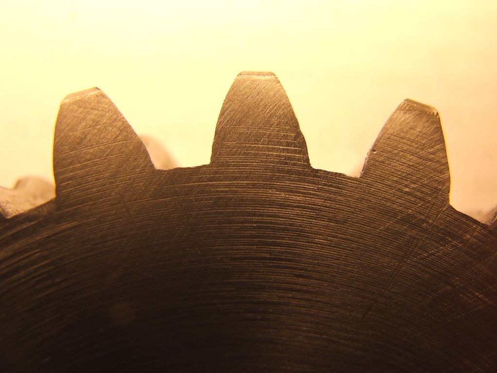
                Looking at the end of the teeth they seem slightly asymmetric to me:

                worm wheel tooth.jpg

                But of course that could just be iffy machining. crying

                Regards,

                Andrew

                #132722
                jason udall
                Participant
                  @jasonudall57142

                  My guess .the original was filed to fit and run for polish..tight wears and clearance doesn’t matter..this is why things used to be “run in”..
                  The engineering/design fascinates me. But it might be the curves and surfaces “generated” by the run -in meshing set differ from our ideal in subtle ways … …

                Viewing 7 posts - 26 through 32 (of 32 total)
                • Please log in to reply to this topic. Registering is free and easy using the links on the menu at the top of this page.

                Advert

                Latest Replies

                Viewing 25 topics - 1 through 25 (of 25 total)
                Viewing 25 topics - 1 through 25 (of 25 total)

                View full reply list.

                Advert

                Newsletter Sign-up