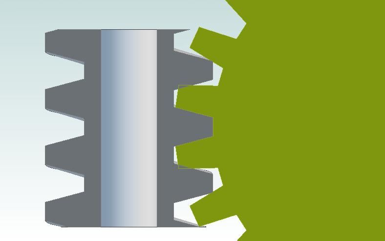
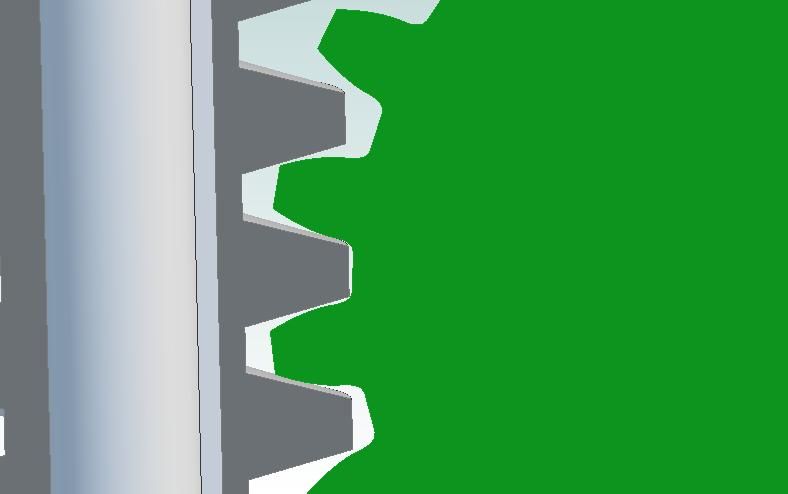
In Andrews thread "Worm and worm wheel design and manufacture" I posted a picture of the worm wheel I drew after looking at a solidmodel drawn by Martin. I thought it might be helpful to show how I did it in Solidworks as the same method would be reasonably generic in most 3D cad suites.
1. Started with a simple extrude of the blank
Next was the tooth form, this was a "cut sweep" along a helix. The cut sweep simply makes a cut using a shape that you draw (a tooth shape for this) and moves it along the guide line, in this case a helix (or half a helix to enable me to start in the middle as this is where the worm geometry is representative of a rack).
I then did it all again in the other direction to make the other half of the tooth cut….
The next step was to simply "revolve cut" the circular profile for the worm root around the blank…….
And that was the hard bit done! The next steps just fancied it up a bit for the realistic render job….
Add bore, keyway and chamfers…..
And by way of trying to show that it is close to realistic, I have also got one of the wheel sectioned with the diameter on it for scale…
Mark is absolutely correct, though the detail might differ in other parametric 3D CAD packages the same basic techniques would apply.
Often the biggest difficulty in modelling a part is 'getting your head around' how to approach the task (splitting it into discrete simple features) – seeing how others have tackled similar items is always useful.
Constructing a 3D model has a lot in common with machining. Projected 2D views 'drop out afterwards' with little effort. Updating drawings to reflect a design change is really simple because the drawings remain linked to the 3D model and update automatically after changes to the model.
3D vs 2D is a different mindset though, so making that change on top of learning new software does take time.
I'd agree that 3D solid modelling is actually probably easier for machinists to understand than 2D drawing. Mostly because it is possible to start off with a solid blank and cut away bits, just as is done with machining. If you are the machinist, then this process will become a simulation of how easy it is to make too. If you can't model it, then the chance of being able to make it easily is low.
Both mine and Mark's models are only approximations of the real thing, I think that an accurate model might be quite a bit harder to do as the profile of a tooth changes constantly along its length.
The model I drew was a "very close" approximation because I don't have the exact dimensions for the worm. Had I had these, I could have produced solid models of the parts that would be an accurate representation including clearance etc. They would not have been any harder unless the profile of the tooth was not "normal" (at 90 degrees to the path) and this would have only required a plane be created at the correct inclination. The only other thing that may have made it harder would be an involute form which requires construction geometry to draw the profile form, other than that the same process would work.
What I am saying is that it I don't think it's as easy as sweeping an involute tooth profile along the helix because the profile shape needs to change depending upon where it is on the helix. I think this would become more apparent as the teeth start to come up around the sides of the worm. So maybe more of a Loft than a Sweep?
This is a very interesting discussion, so many thanks to the contributors so far. I'm impressed with the worm gear drawn by Mark, but as has been suggested I think the tooth shape is incorrect, sorry to be a party pooper.
If we take a very thin slice of the worm wheel and worm we essentially have a rack and spur gear. To mate properly the spur gear will need an involute tooth form appropriate to the DP, pressure angle and number of teeth. That seems simple enough, but the question has been raised about what happens to the tooth form as the worm wheel envelopes the worm. It's a damn good question, and one to which I don't have a proper answer.
First, some experimental evidence. A while ago, when I was thinking of machining the worm wheel on a CNC mill I did exactly as has been suggested. I took an involute tooth form for a 6.283DP, 22 tooth gear with a pressure angle of 15° and extruded it along a helix on the lead angle of the worm. An assembly of the 'prototype worm wheel' with a worm seems to show that the tooth form on the outside of the worm wheel did not mesh properly with the worm. Here I think I agree with Martin that the tooth form is not a simple sweep operation, but I'm open to being proved wrong! In which case I might have wasted my time making the hob.
So what about the theoretical explanation for the change in tooth form as you move around the worm? I don't know, but how about the following as a starter for ten? We start by stating that the tooth form of the worm wheel at the centre is identical to that of a spur gear of the same DP, number of teeth, and pressure angle. Anybody disagree, and if so why? If we move slightly round the worm, and take a radial out from the centre of the worm, as I see it the effective pitch circle diameter of the mating thin slice of worm wheel gets larger. But the circular pitch, and DP, and the number of teeth stay the same, as the pitch of the worm is a constant. But the PCD of the worm wheel has changed, so something must give. Here is where I'm a bit fuzzy [1]. I think that the tooth form gets thinner, but I currently have no real explanation as to why.
So what do other people think, am I talking sitting bull?
Regards,
Andrew
[1] I might also be fuzzy because I'm on my third glass of red wine in memorium for the Pawnee. That's the aeroplane I'm sitting in, in my avatar. It's just been sold, and is on it's way to South Africa to start a new life as a crop sprayer. I flew it from Cambridge up to East Winch, near King's Lynn, this morning to start that journey. It seemed really strange taking off from Cambridge for the last time, and even stranger walking away from it at East Winch and coming back to Cambridge in a different aeroplane. It's a bit sad, as I really loved flying the Pawnee.
Presumably you could choose to generate the correct wormwheel profile to work with your worm or you could generate the correct profile for your worm to suit your wormwheel. I expect the ideal(?), approved profile would be between the 2. Obviously I have no idea what that profile would look like or how you would derive it but I bet someone has written a thesis about it….
Yes, if you want to get flank contact then you are correct about the involute form – due to the rolling action of the worm flank on the wheel (it being single enveloping). For a steering gear set on a scale model – do you want this degree of fidelity or would something that works be sufficient? What I drew would provide a contact arc that would sweep up or down the tooth flank as it rotated through the central tangent point.
I could also draw the tooth form as it would be if "generated" (as if cut by a rotating worm "generating" a contact surface as it rotates – this is a little hard to imagine at first if you have never seen it done but try imagining the moving contact surface) by using a lofted cut as you mention.
For all those who don't know, a loft in 3D cad is a tool that allows you to draw a shape on one face, a path to another face and a different shape at the new face and then have the software "cut" the material away along the path and "morf" the shape as it goes eg. change a round hole into a share hole along a path between to faces. This is possible to make with modern industrial tools – the obvious tool that can do that circle square thing would be a conical cutting wire erroder! If you want absolute control of the tooth form I could plot the profile mathematically and generate a "point cloud" at whatever precision you require and use this to drive the cut profile and path but that is getting significantly harder.
Unless I missing something I just don't see how a worm wheel with straight sided teeth can mate with a Acme form worm? Here's a CAD section through a worm wheel, where the tooth space is a copy of the worm thread form.
The sewction seems to indicate that the worm interferes with the adjacent teeth. Here's a similar thing, but with an involute gear form:
I haven't got the tooth depth correct, but it's a right pain to go back and regenerate the gear, export to DXF, import the DXF, fix the sketch, extrude it and so on. The picture does seem to indicate that the worm does not interfere with the adjacent teeth.
So as far as I can see an 'Acme form' worm wheel doesn't work, unless the teeth are made narrower, or the centre to centre distance is increased? Is that correct?
For the sake of argument let's assume that we've got an involute tooth form at the centre of the worm wheel. The question is what form does the worm wheel tooth shape take as we move round the worm, away from the centre line? I assume it's not simply a 'copy' of the central involute form, so what is it?
The drawings for my traction engine show a 2 start steering worm of 0.5" pitch and OD of 1.48" and a mating 22 tooth helical style gear. There is nowhere near enough information to actually make the parts, and they're nothing like prototypical. As has been pointed out on another forum no traction engine had a two start steering worm, as it will backdrive. Out of neccessity I have had to define the worm tooth form, and I want it to mate with a proper single enveloping worm wheel. I also want to know why the tooth forms are the shape they are and why they vary in the way they do. No doubt there are simpler means of getting some sort of functional steering mechanism, but they don't interest me.
I have no experience with this type of worm/worm wheel, only with driven worms with pitch between 0.8 and 3.0mm. But you asks what happens with the worm wheel tooth shape as it moves around the worm. It will stay the same as the centre line of the worm wheel tooth when it shapes around the worm is not a straight line but an arc of half the diameter of the wheel+worm, with the centre line of the worm as middlepoint. Niko.
Right then, so I decided to do it! I "generated" the form by subtracting a worm form solid body rolling around the pitch circle of the wheel while rotating by the correct angular relationship (IE. 1 worm rev divided into the pitch) and have attached the resulting solid body. You should see that we are all wrong (I think) as the form is only really involute at the mid plane. As Andrew identified, the profile tends to become closer to the rack form at the sides as they approach 90 degrees for a fully enveloped wheel.
Anyway, depending on how many axis Andrew has on his mill (3 aren't enough) he should be able to get close to my solid body and as stated at the beginning, I can draw the thing at whatever precision he wants but the time and complexity go up in step. If you really look, you should also be able to see that I messed up the model on a few cuts and this resulted in 3 of the 10% increments failing – they are the ones that look like bigger steps than the others!
Mark
PS. sorry it is not enveloping, it is late and I forgot when I extruded the blank……. also, this is really getting way past basic modelling so don't be put off if you are learning 3D, I know quite a number of pro cad jockeys that would not be able to do this stuff without help.
Mark: Thanks for creating the modified extruded worm wheel. The idea that the tooth form tends towards a rack fits in with my idea that as you move around the worm the theoretical size of the mating worm wheel increases. At 90° to the centre line the theoretical size would be infinite, aka a rack. However, other posters have stated that the tooth form doesn't change. I suspect it's time for me to stop worrying about the theory and have a go at cutting a worm wheel and see what happens. The hob is cooking in the furnace as I type this ready for hardening.
On reflection I'm not convinced that my idea of the theoretical size of the mating gear increasing as you move round the worm is sound. Assume that we have a very thin worm wheel, essentially a spur gear with the appropriate involute tooth form. As we move away from the centre line the diameter of the very thin gear will need to increase, so as to still engage with the worm. However, the tooth form will need to get deeper, as the effective depth of the thread on the worm is deeper. An obvious question; is this deeper tooth form simply a linear distortion of the involute form of the mating gear if it were radial to the worm?
Andrew, I have not tried to calculate the relationship but it is bound to have some trig function (or combination) relating the form to angular displacement. If it helps, the worm gear rack thing has to hold true at the 90 degree point as it is effectively a section through a screw thread at this point. The other thing that is noticeable is the non symmetric tooth form on the wheel – this must be related to the helix angle (which was why I originally thought it might require the tooth form cut profile drawing on an inclined plane rather than the normal plane).
John, the idea that it has to be an involute form is not as strait forward as it first appears – as the form is generated by a line that is both rotating and inclining (I think). To be involute it would imply a line tangent to an arc on a flat plane. This is why the non symmetry occurs?