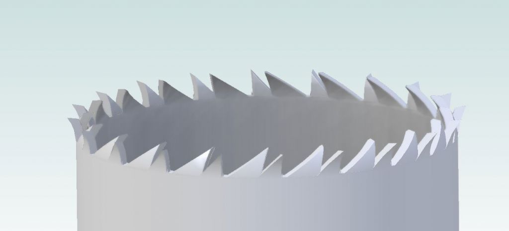
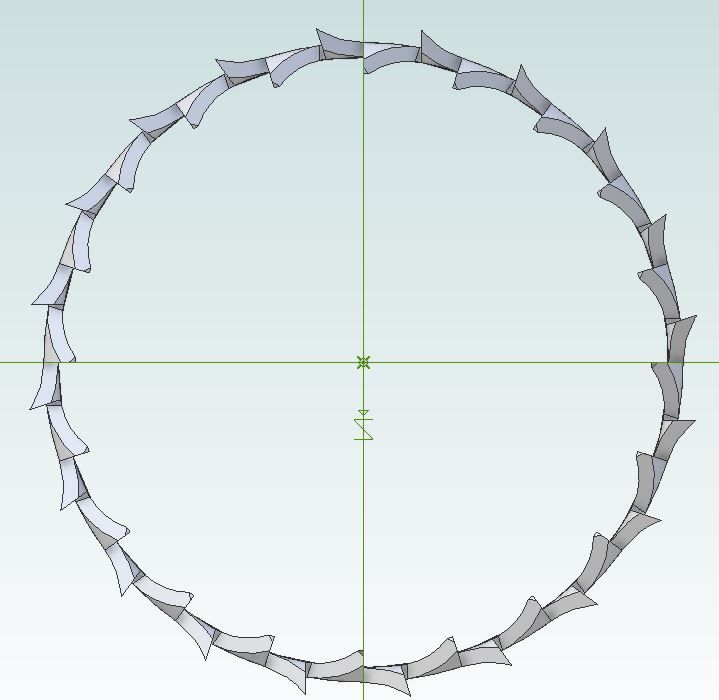
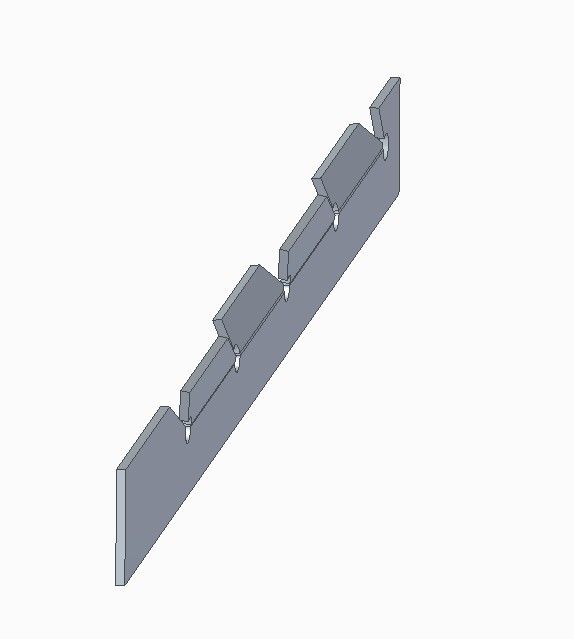
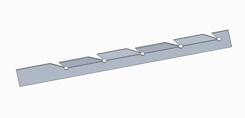
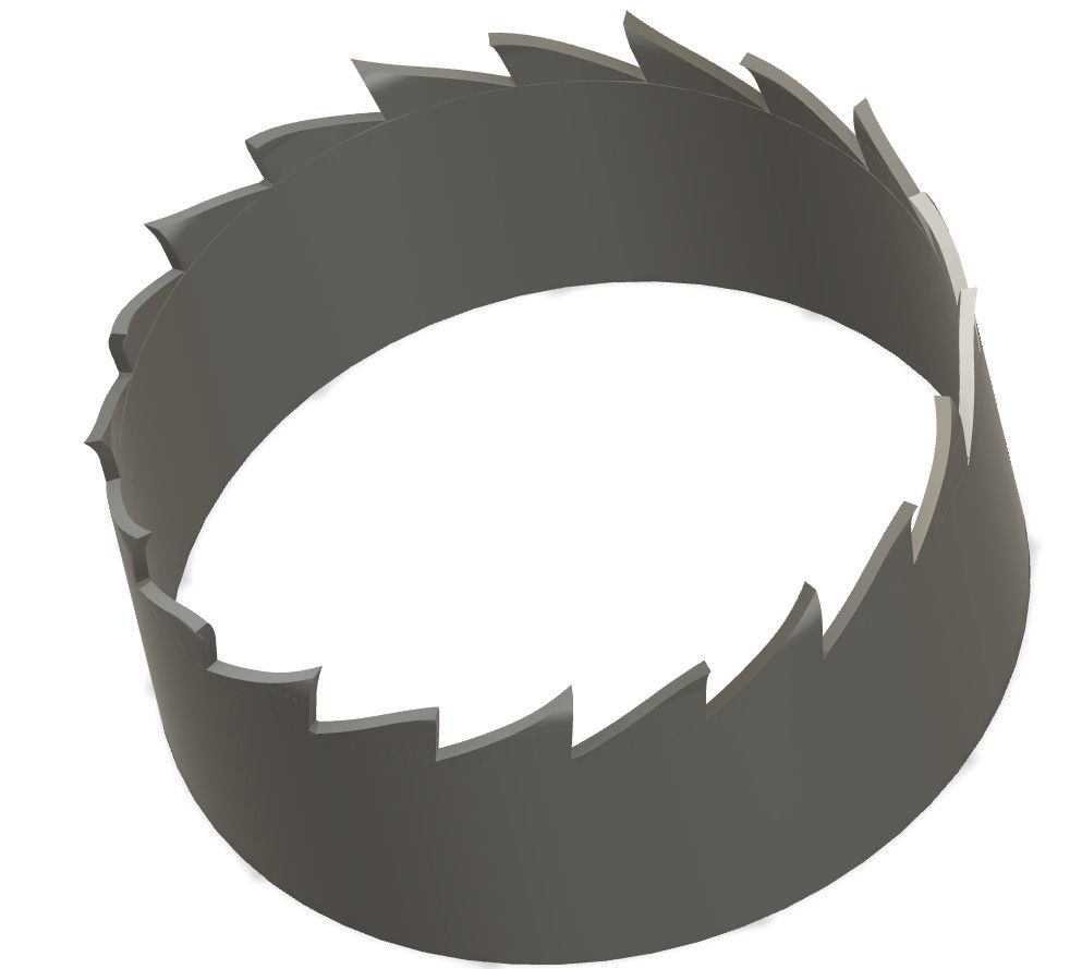
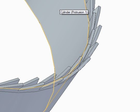
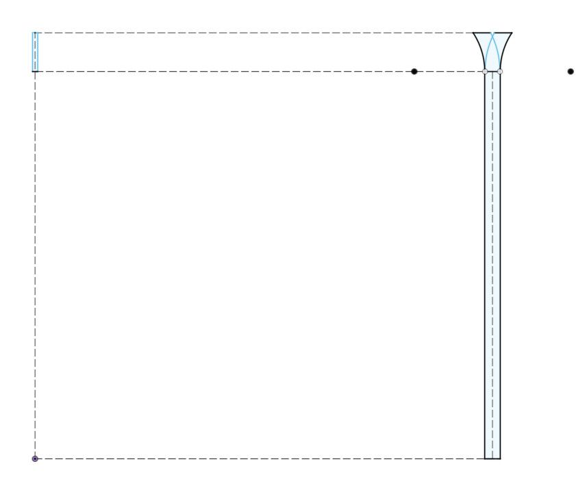
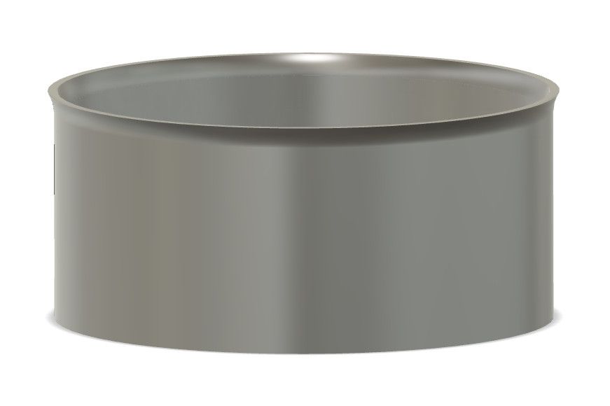
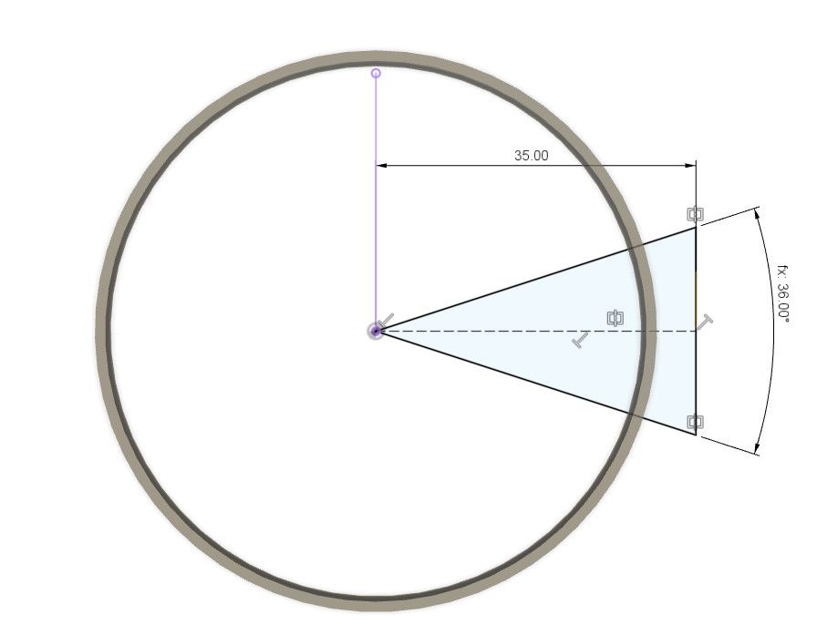
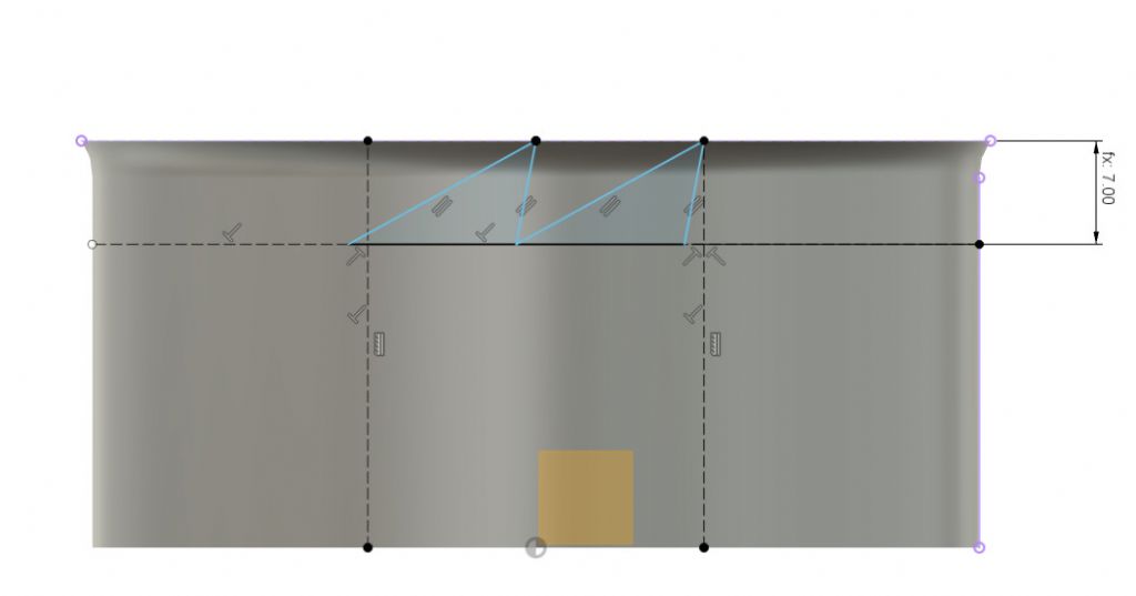
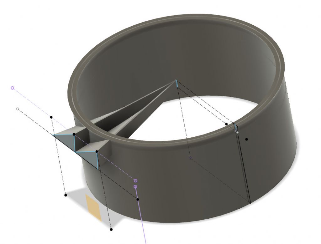
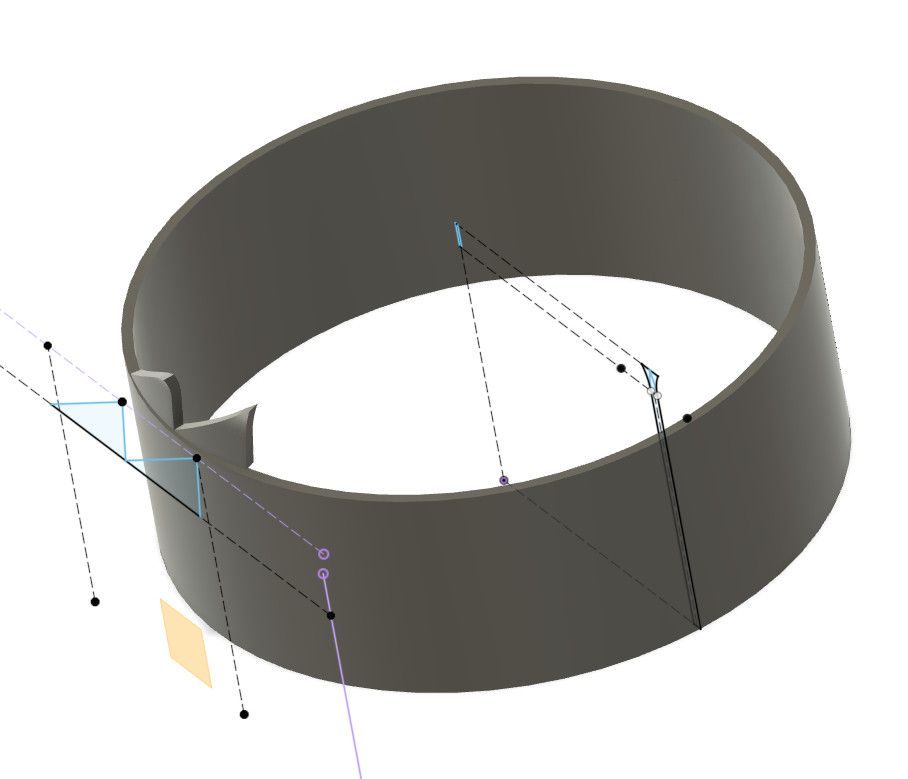
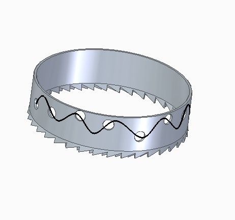
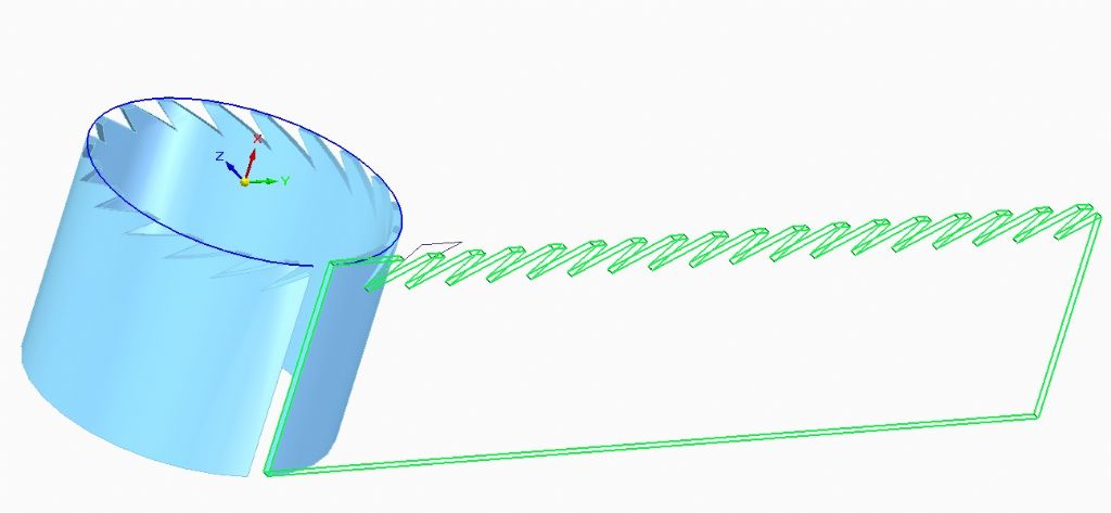
Drawing a saw blade – help!
Drawing a saw blade – help!
- This topic has 28 replies, 13 voices, and was last updated 4 December 2022 at 21:21 by
Model Enginerd.
- Please log in to reply to this topic. Registering is free and easy using the links on the menu at the top of this page.
Latest Replies
Viewing 25 topics - 1 through 25 (of 25 total)
-
- Topic
- Voices
- Last Post
Viewing 25 topics - 1 through 25 (of 25 total)
Latest Issue
Newsletter Sign-up
Latest Replies
- Mistry dividing attachment
- Hopeless…Alibre Ass
- Lidl castors
- Epoxy or acid etch primer
- Diving in to ATC?
- What Did You Do Today 2025
- Measuring a double Vee lathe bed Vee position
- Please direct me to where I can find an engineer to do some bespoke work
- Making Unimat DB/SL Steadies
- Bad design, or am I missing something?


