DIY magnetic DRO

Advert

DIY magnetic DRO

Home Forums Workshop Tools and Tooling DIY magnetic DRO

Viewing 25 posts - 51 through 75 (of 84 total)
  • Author
    Posts
  • #421232
    Michael Gilligan
    Participant
      @michaelgilligan61133
      Posted by SillyOldDuffer on 28/07/2019 09:48:37:
      [ … ]
      No luck here finding a description of them on the web though! Does anyone know how they work?

      .

      These guys: **LINK**

      https://www.researchgate.net/publication/307610351_The_Front-End_Readout_as_an_Encoder_IC_for_Magneto-Resistive_Linear_Scale_Sensors

      MichaelG.

      Advert
      #421253
      SillyOldDuffer
      Moderator
        @sillyoldduffer

        Many thanks Michael, I don't know how you find this stuff! The paper led me to this web-site which – if I've understood it- describes another way of measuring linear position.

        The magnetic tape (they call it a waveguide), is made of aligned magnetostrictive elements. When the head transmits a magnetic pulse, the magnetostrictive elements produce an ultrasonic pulse that travels to both ends and reflects. Measuring the time taken by both to return to the head gives the position of the head. It's like RADAR.

        Scary how much I don't know. Every answer makesat least two new questions!

        Dave

        #421256
        ChrisB
        Participant
          @chrisb35596

          The magnetic strip is a magnet ( not a powerful one ) so yes some little ferrous fragments will stick to it. But I'm not too worried about it, the fragments that stick are few and small, and as the magnetic field is not strong it is very easy to wipe off. Besides that the strip is covered with a thin stainless steel foil which will protect the magnetic strip from abrasion and hot chips etc.

          The area below the chuck is covered by a swarf tray attached to the carriage so not much will fall in between the ways on the lathe bed, and in any case I will have a better view if there's dirt accumulation and have better access to wipe it off.

          If it becomes an issue I can always take off the tape and place it somewhere else, that's the beauty of sticking things rather than bolting! wink 2

          #421259
          Michael Gilligan
          Participant
            @michaelgilligan61133
            Posted by SillyOldDuffer on 28/07/2019 11:08:31:

            Many thanks Michael, I don't know how you find this stuff! The paper led me to this web-site ..

            .

            You're welcome, Dave

            … but could you please reciprocate by correcting the hyperlink that you included

            MichaelG.

            #421528
            old mart
            Participant
              @oldmart

              Are the guidelines regarding reusing the tape ok with the possibility of it stretching?

              #421540
              ChrisB
              Participant
                @chrisb35596
                Posted by old mart on 29/07/2019 20:09:30:

                Are the guidelines regarding reusing the tape ok with the possibility of it stretching?

                Stretching? Didn't quite get how that could happen, maybe we're not referring to the same thing. The magnetic tape I'm using is not a tape pre se, not like a cellulose tape. It is a stainless steel strip with magnetic material bonded onto it with double sided tape applied to the stainless strip (by the manufacturer). I just peel the backing film off the strip and attach it to wherever I require it. If I should need to take it off, I'll slip a blade under the tape and lift it off. Can't think of a way I'd be able to stretch it, I think it would be fine.

                In any case I started installation of the DROs on the mill, should be ready by tomorrow. I threw some iron filings from the bandsaw at the tape and some will stick, but it's very easy to dust it off and none will get under the readhead as there's no gap. Will post some photos of the installation tomorrow.

                #421554
                Douglas Johnston
                Participant
                  @douglasjohnston98463
                  Posted by ChrisB on 29/07/2019 21:38:52:

                  Posted by old mart on 29/07/2019 20:09:30:

                  Are the guidelines regarding reusing the tape ok with the possibility of it stretching?

                  Stretching? Didn't quite get how that could happen, maybe we're not referring to the same thing. The magnetic tape I'm using is not a tape pre se, not like a cellulose tape. It is a stainless steel strip with magnetic material bonded onto it with double sided tape applied to the stainless strip (by the manufacturer). I just peel the backing film off the strip and attach it to wherever I require it. If I should need to take it off, I'll slip a blade under the tape and lift it off. Can't think of a way I'd be able to stretch it, I think it would be fine.

                  In any case I started installation of the DROs on the mill, should be ready by tomorrow. I threw some iron filings from the bandsaw at the tape and some will stick, but it's very easy to dust it off and none will get under the readhead as there's no gap. Will post some photos of the installation tomorrow.

                  Some double sided adhesive tape can be very difficult to remove, as I know from bitter experience. Better to make sure it is in the best place from the start.

                  Doug

                  #421863
                  ChrisB
                  Participant
                    @chrisb35596

                    Found some time yesterday and this morning to install the Mill DRO. Takes some fiddling with the read heads to get them aligned properly, but other than that the installation was realy easy. No holes to drill into the machine, some simple brackets, just tape and go!

                    Had to remove and modify the slideway covers to make space for the read heads, that took me some head scratching and time, but finally got something I was happy with – if anyone's interested and would like to know how I did it etc, I'll open another thread.

                    Here's some pictures of the progress.

                    Installation of the magnetic tape on the X-axis, I only needed to set up and align the read head. Then while traversing the table and peeling the backing tape, the read head aligns the magnetic tape.

                    20190729_152550.jpg

                    Same thing for the other axes.

                    20190731_094604.jpg

                    Y-axis installation. To avoid drilling and tapping into the saddle I glued a plate with a stud on to the saddle, then attached the read head on a slotted bracket which is in turn is held by a nut on the glued plate. ( I used scotch weld EC 2216 for attaching the plate to saddle – not going anywhere with it)

                    20190731_123456.jpg

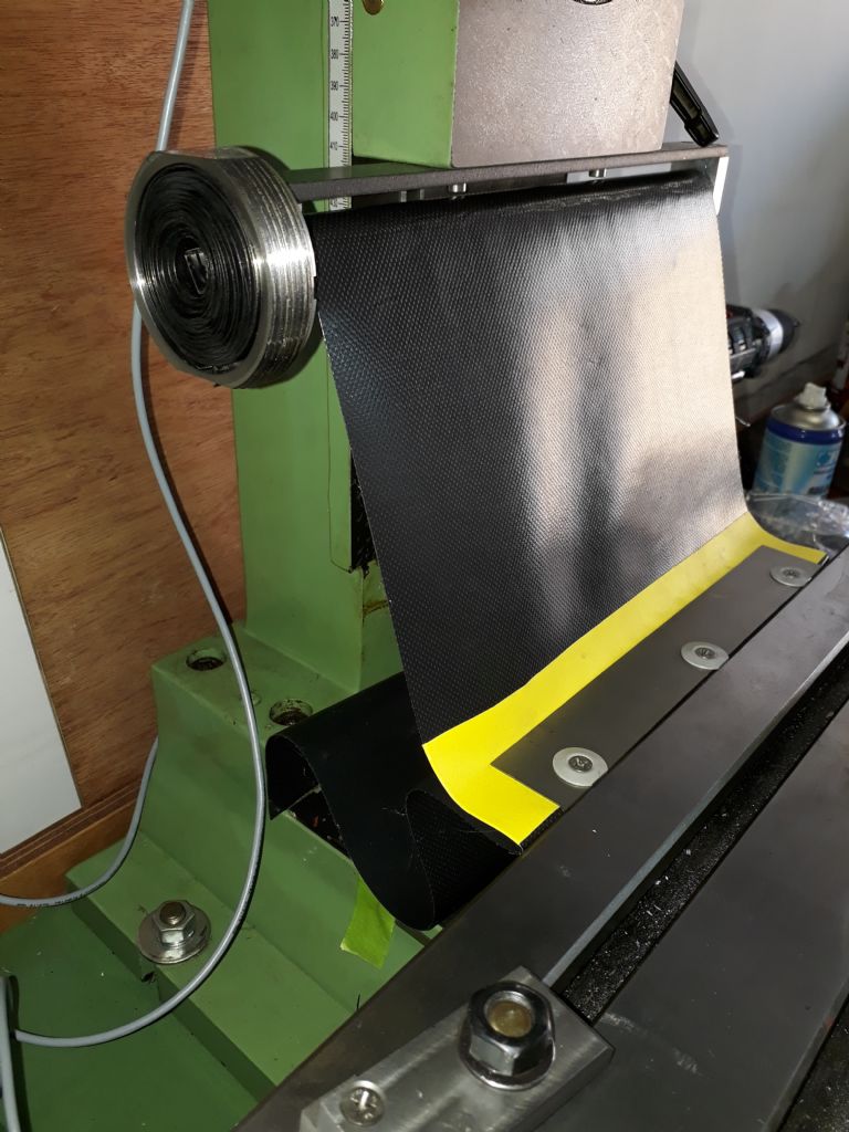
                    This is the swarf cover for Z and X slideways. Had to remove the original ones to make the read heads fit. In a nutshell it's a sort of roller blind so rather than hanging around when raising/lowering the head, and when traversing the X-axis – the cover will stow itself like a roller.

                    20190731_123306.jpg

                    This is how the Y-axis looks like under the slideway cover. The bracket for the read head is bolted using an existing hole.

                    20190731_123528.jpg

                    The only thing which bothers me is the wiring. I placed the extra wires in a conduit, but the rest are hanging loose. The thing is the cables need slack to allow for the movement of the head and table, but it's not neat. I have to figure out something better.

                    20190731_123823.jpg

                    #421873
                    Clive Foster
                    Participant
                      @clivefoster55965

                      Commercial systems frequently use flexible metal conduit of 6 or 8 mm bore to protect the wires. Various types and finishes can be found. Typically £1 to £2 ish per metre in 25 metre rolls so not inherently silly expensive but finding folk who sell shorter lengths is a problem.

                      Clive

                      #421937
                      ChrisB
                      Participant
                        @chrisb35596

                        Unfortunately I can't do that at this stage, not unless I take the connectors off. I had a look at photos DROs installations and most of them have wires hanging freely. So I will find some split type conduit and try to route them as best I can.

                        Tomorrow I'll be doing the lathe, which should be easier.

                        #421938
                        JasonB
                        Moderator
                          @jasonb

                          Most hand freely in the flexi conduit which protects the wire from damage. It's a bit like small diameter shower hose.

                          #422411
                          ChrisB
                          Participant
                            @chrisb35596


                            Latest update: Lathe DRO installation.

                            Installed the read heads on the lathe X and Z axes between yesterday and today. The idea was to install the X axis read head and magnetic tape inside the carriage cross slide. While it was possible, it was a bit difficult to do given the limited space and the leadscrew. But following Jason's idea I managed to fit it somehow.

                            Here's how I went about it:

                            As I did not want to drill any holes in the carriage I glued a plate with an m5 stud to which I would mount the read head bracket. Here I had to take measurements carefully to make sure the leadscrew nut on the crosslide would not hit the head when it's at the end of it's travel. Also to be noted, that the crosslide cannot be removed by sliding it rear wards for the above mentioned reason.

                            20190803_110153.jpg


                            Here's how the X axis read head is attached to the carriage. It's a tight squeeze and a bit fiddly to get to the read head screws (M2.5 allen cap head), but not impossible. I glued a plate to the crosslide which has a dual purpose – the primary purpose is to attach the magnetic tape to the under side, the secondary purpose is to cover and protect the read head and tape from swarf, dust, oil etc. ( in the photo the crosslide is over extended just to show the setup – in normal operation the slide will cover the head.

                            20190803_112123.jpg


                            This is the magnetic tape on the bottom face of the crosslide. Worth noting that the magnetic strip is about 2mm thick, this means that I have to be careful when dismantling the crosslide. There is not enough clearance for the strip to slide between the carriage and the crosslide, so if I attempt to slide the crosslide off I'll damage the strip. The correct way to take the crosslide off is by first sliding and removing the gib strip, and then LIFT off the crosslide.

                            20190803_123559.jpg


                            Next it was the turn for the Z axis installation. I attached the read head to it's bracket loosely. Then the bracket to the carriage was glued, keeping every thing clamped and aligned and left overnight for the adhesive to set.

                            20190803_110228.jpg


                            This is after the adhesive set, next was to install the magnetic tape.

                            20190803_112211.jpg


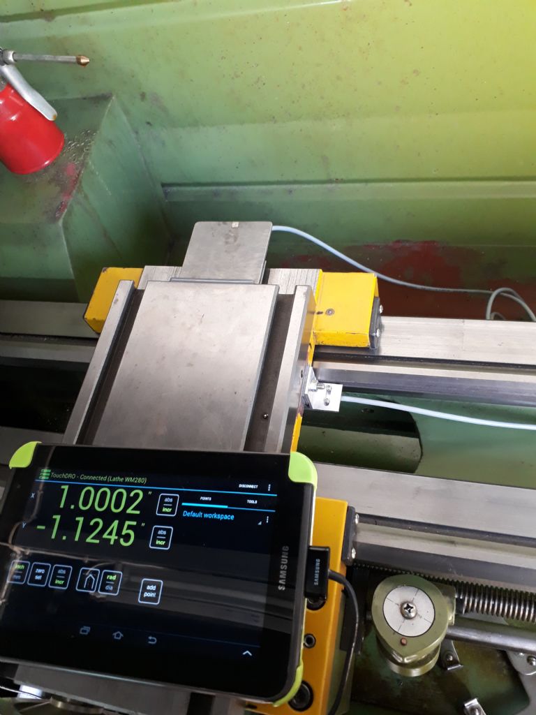
                            Everything now in place, time to check every thing works and calibrate the readouts.

                            20190803_123436.jpg

                            All that remains is tidying up the cables and build a couple of cases for the touchdro circuit boards as they are still just a circuit hanging on cables!

                            In conclusion, I would say there was a fair amount of work to make a DIY set of DRO's for the lathe and mill, and if you're in a hurry it would definitely make better sense buying them new. But, for half the price or less, if you have time, it's worth a try to build your own – no special skills required, just patience – a lot of it!

                            Edited By ChrisB on 03/08/2019 14:09:49

                            #422715
                            ChrisB
                            Participant
                              @chrisb35596

                              I got s piece of nylon 6 black sheet from which I'll probably make the cases for the touchdro circuit boards. Any recommendation on how to mill the material, that is, feeds, speeds and cutter types – Iast time I tried milling plastic (it was HDPE I believe) I ended up with a blob of molten plastic and taking it off the endmill is something I'd like to avoid!

                              The choice of cutters I have are 4 and 3 flute endmills of various sizes (3-12mm)

                              #422759
                              Ian P
                              Participant
                                @ianp

                                Main thing with machining plastics is to have sharp cutters, razor sharp new ones if possible. Too high a speed in conjunction with dull cutters, or cutters that do not clear the chips quick enough will cause heating and melting of some plastics.

                                I dont think I have ever milled nylon but I dont like using in the lathe, it produces stringy swarf which can get wrapped round the tool and job, Acetal by comparison is very easy to machine. Last week using a new long series 12mm 2 flute endmill I cut 100mm square holes in 60mm thick Delrin by plunging full depth before moving X and Y in one pass, then a finishing cut to size.

                                I am impressed with your DRO project and I will definitely by doing the same once I clear my current backlog of jobs.

                                Ian P

                                #422852
                                ChrisB
                                Participant
                                  @chrisb35596

                                  Thanks Ian, it's a very doable project if you have some time to spare – I'll be happy to help you out any way I can when the time comes for you to do it.

                                  Re. Nylon, I have some new carbide 3 flute end mills – will try that first. If it does not work I get a 2 flute. Will have to wait anyway as I cant go to the workshop for now – got a nasty jellyfish sting on my wrist, can hardly move it sad

                                  #422877
                                  Clive Foster
                                  Participant
                                    @clivefoster55965

                                    Chris

                                    Splendid job so far.

                                    Bin the nylon and splash out on some acetal / delrin for the cases. As Ian says Delrin machines like a dream with sharp cutters decent feed and not too much speed.

                                    Nylon is (marginally) better to machine than HDPE but its still a miserable experience. Main saving grace is that it will behave given the right combination of fairly low speed, high feed and high depth of cut. Rather grade and condition sensitive in my experience. Sort of thing you can dial in on a lathe but not really Home Shop mill compatible. Especially if you hardly ever use the stuff and will have forgotten what works by next time.

                                    Clive

                                    #423016
                                    Paul L
                                    Participant
                                      @paull58212

                                      Hi ChrisB

                                      Can you help me with the reading head selection please?

                                      I think this head LINK (although a little bigger than your choice) means i don't have to make a custom board to mount the sensor onto. Can you tell me which option i should select? i think a 10um resolution should be ok but i have no idea about frequency or ref marks.

                                      Also the MS05 magnetic scale, was this your selection also?

                                      Any advice greatly appreciated.

                                      Paul

                                      #423053
                                      ChrisB
                                      Participant
                                        @chrisb35596

                                        Hi Paul, the encoder I used have a 1um resolution and 2Mhz frequency. The tape is the MS05, correct.

                                        This is the spec and part no of what I used – the tape pn will vary according to the length:

                                        RLC2HD miniature linear PCB level incremental magnetic encoder

                                        Product description
                                        [HD] – Incremental, no line driver, 5 V [A] – N/A (standard) [2D0] – 2000 (1 µm) [B] – 0.5 μs (2 MHz) [00] – No connector [C] – Periodic reference as per scale pitch (2 mm) [00] – None (standard) [] – [B] – ±40 μm/m [M600] – Length in mm (less than 1 m) [B] – VHB back-adhesion tape, with cover foil [0000] – No reference mark [] –
                                        Product part number
                                        RLC2HDA2D0B00C00-29.6€;MS05BM600B0000-28.28€

                                        Whether or not the the one you linked will work, I cannot tell – but they do have similar specs.

                                        Chris

                                        #428836
                                        Paul L
                                        Participant
                                          @paull58212

                                          Hi ChrisB,

                                          In the end i ordered the same readheads as you and everything arrived today. I made the pcb's on a mini router. (i had lots of problems trying to photo-etch them!)

                                          What technique did you use to solder the readheads onto the pcb? I was going to attempt it using a fine tip iron but someone told me that its impossible to do it that way.

                                          As always, any advice greatly appreciated.

                                          Paul

                                          #428953
                                          ChrisB
                                          Participant
                                            @chrisb35596

                                            I'm not sure if the photo-etch pcb board have some coating which needs to be removed for solder to adhere.

                                            For mine I applied solder along the traces of the pcb first. The readhead chip has exposed points on it's back side ( like little gold dots) and to prevent shorting them I applied some clear coat on it's back. I then put the RH chip in place on the pcb and applied a minute ammount of superglue to keep it in place for soldering. For soldering I have a Lidl variable temp iron, I replaced the brass tip with a diy pointed copper tip. Applied flux to the contact points and soldered on…pretty straight forward but quite fiddly as every thing is so small. Probably there are better ways how to do it, but this is my way round it.

                                            #437581
                                            Jed Martens
                                            Participant
                                              @jedmartens56976

                                              Hi Chris – how is your magnetic DRO system working? I've considering using the same components for adding a DRO to my mill. I think the version with integrated RS422 driver would works best my case (differential signalling having better noise immunity)…

                                              My main question – do you see any issue with using the high accuracy versions (~1/4 micron per edge, 8192 edges per 2mm)? Assuming the electronics at the far end can cope with the data-rate of course. I know that the mill isn't that accurate (and the operator even less so) but I see no obvious reason for going with a coarser output.

                                              #437730
                                              ChrisB
                                              Participant
                                                @chrisb35596

                                                Hi Jed, I went for the 1μm resolution as the most common type of commercial read heads are 1 or 5μm. Don't know if higher resolutions are better but for what I do, the 1μm resolution encoder is more than enough.

                                                #438217
                                                Jed Martens
                                                Participant
                                                  @jedmartens56976

                                                  I've been thinking about how to mount the magnetic tape and head to my mill. My idea is to make an aluminium bracket and bolt that to the x-axis of the table, with the tape on the underside facing down. The head will be under that facing up. As in the diagrams at the bottom of this post (apologies for my amateurish modelling).

                                                  Are there any obvious draw-backs to doing it this way? It seems that the whole ensemble is better protected from crude (and me dropping things on it), and the read head is easier to mount. I'll make an enclosure to fit over the read head too, similar to what Chris has done.

                                                  dro1.jpg

                                                  dro2.jpg

                                                  #438237
                                                  ChrisB
                                                  Participant
                                                    @chrisb35596

                                                    I think it's a better idea to leave the magnetic tape accessible, small chips will find their way anyway and stick to the magnetic tape. So I'd rather have the tape mounted in a way I can easily brush or wipe off dirt and chips.

                                                    Also keep in mind that the encoder needs to have room for adjustment as it has to ride at a certain height and in the middle of the magnetic tape. I built the readhead case with this in mind so that I would require minimal setting up and adjustment.

                                                    Chris

                                                    #438240
                                                    Ian P
                                                    Participant
                                                      @ianp

                                                      I quite like the way Jed proposes to mount the tape and sensor as it really does protect the tape. There is no reason why the tape mounting bracket has to be a one piece component and I would bond the tape to a (say) square or rectangular beam and then have a length of unequal angle fixed to the top surface with the longest face coming down well below the sensor.

                                                      As I understood it, whilst the tape has a magnetic pattern in it, the amount of magnetic force is so low its unlikely any swarf or chips would stick to it, maybe ferrous dust might accumulate but with the protective stainless foil over, it would be easy to wipe off once every few years.

                                                      Ian P

                                                    Viewing 25 posts - 51 through 75 (of 84 total)
                                                    • Please log in to reply to this topic. Registering is free and easy using the links on the menu at the top of this page.

                                                    Advert

                                                    Latest Replies

                                                    Viewing 25 topics - 1 through 25 (of 25 total)
                                                    Viewing 25 topics - 1 through 25 (of 25 total)

                                                    View full reply list.

                                                    Advert

                                                    Newsletter Sign-up