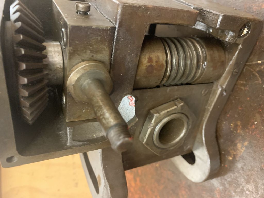
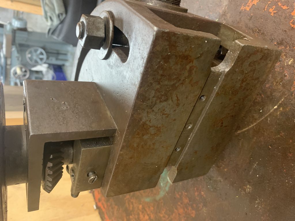
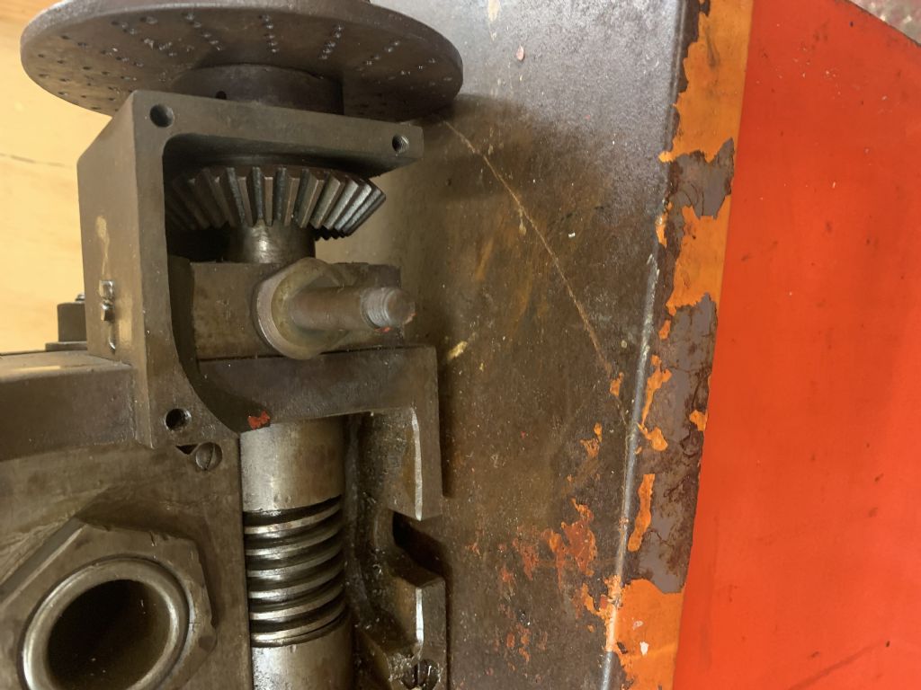
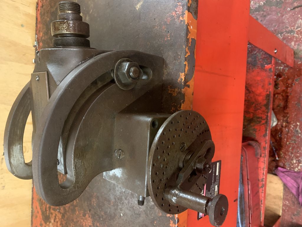
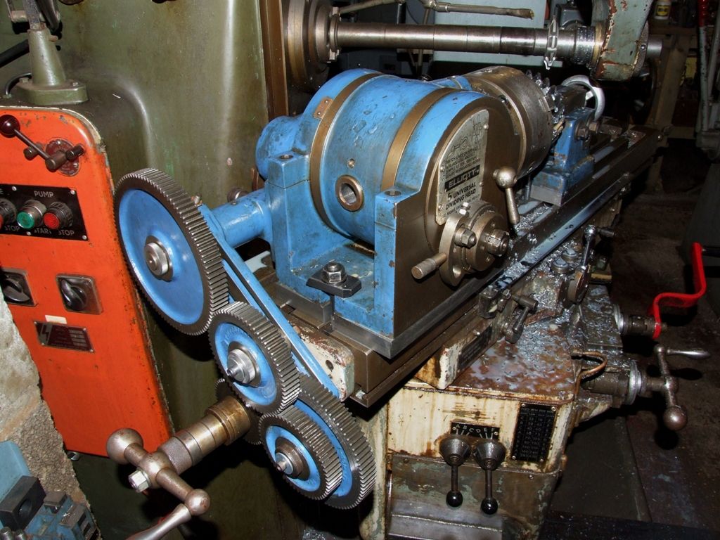
Hi – recently been given a tilting dividing head – can't find a makers mark on it yet but it looks very well made.
It looks like it was taken apart for some reason and the main drive bevel gear is missing along with the handle – the surround doesn't look like too much work to make a new one but the bevel gear is my sticking point.
How do I work out what gear ratio it needs to be – ive not counted the teeth on the gear that remains yet but that's my next job.
Odd that anyone would have removed the gear in the first place, but unless this was some special type, dividing-heads and rotary-tables normally use worms drive, not bevel-gears.
The dimensions of the innards should give you a guide to the sizes required, but unless spares are available for the specific device it's likely you'll have to buy an appropriate stock set (usually 40:1 but not always so verify on the particular head) and modify as and where necessary to suit.
I remember reading something like the worms on small dividing heads and rotary tables are peened in the factory to reduce backlash, as they're too small to fit in any other way of eliminating it. Even with a new worm gear it may be more hassle than it's worth getting it set up correctly because of that.
If it's a well made unit from a decent company that has a few parts missing, and worth saving, there is the option of buying a foreign copy and stripping it for parts.
You might find a bevel gear on the outside if it is a differential dividing head, but the gears on the inside will normally be a worm and pinion. The number of teeth on the pinion would tell you the ratio of the head, it is unlikely to be a multi-start worm. The worm would have to have a tooth form and pitch to match the pinion. Could be made, but is it going to be worth the trouble?
Universal dividing heads had a shaft geared to the hollow shaft that carreis the dividing pates. It could be geared to the table leadscrew for milling helices. In some cases it could be geared to the spindle to enable divisions that were not possible with the index plates alone. That is the only pace I would expect a bevel gear.
The bevel engages with the missing aux. input shaft (and change gears) for milling helix's, it operates via a mill power take off when the division plates are not used.
And if you want to do that you'll need the gear on the end of the mill leadscrew and the banjo and gears to get the desired lead on the helix. But… you can use the dividing head as it stands to index the gear blanks to cut them
Measure the OD of the gear that is present, count the teeth and look to see if HPC, Reliance, Davall, or any of the other gear specialists have to offer. It may be necessary to modify the bore to suit the spindle.
If you know the make and model of the Dividing Head, it may be possible to obtain a replacement gear.
It's common for the drive shaft from the mill table leadscrew to maintain a ratio of 1:1 until it reaches the worm drive on the dividing head spindle. Bearing that in mind, and looking at the existing gear and witness marks, I think the bevel gears are a special case, ie, mitre gears. So we just need a copy of the existing gear in terms of tooth count and angles.
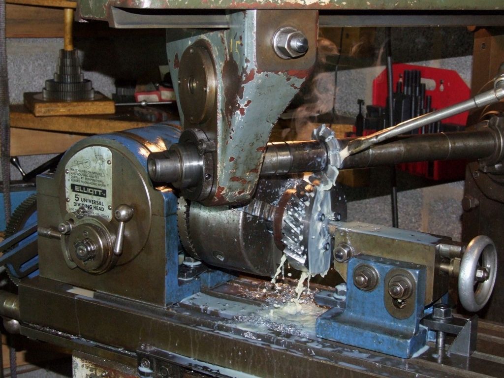
When spiral milling the division plates are still used, unless the helix is single start. While the drive from the mill table creates the helix:
the division plates are still needed for indexing multiple starts:
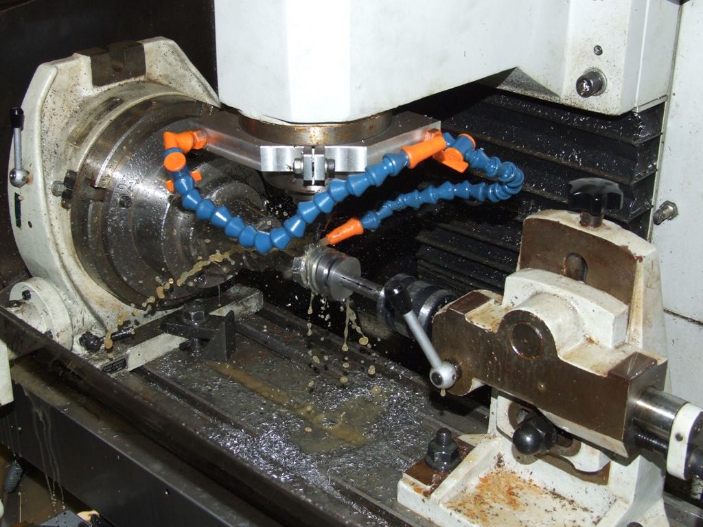
The only time I've machined a single start helix I used a 4-axis CNC mill:
A helix and a spiral are not the same. In a spiral the radius changes as the angle increases. A helix is a special case where the radius is a constant.
Spiral milling is also useful for cutting spiral oil grooves in bearings and shafts when restoring vintage parts.The sets of gears for spiral milling were established in the late 1800s so the tables for the set up are in imperial units to suit mills with imperial leadscrews,on my mill with metric leadscrew I made and used 100 and 127 wheels in the gear train, making the 127 wheel was carried out using differential indexing,the part of this set that requires care is to determine if the index plate moves slower or faster than the worm spindle,
Author
Posts
Viewing 24 posts - 1 through 24 (of 24 total)
Please log in to reply to this topic. Registering is free and easy using the links on the menu at the top of this page.