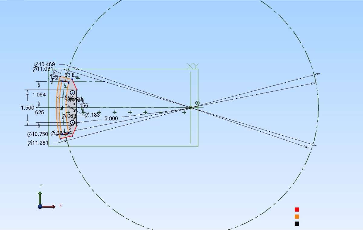
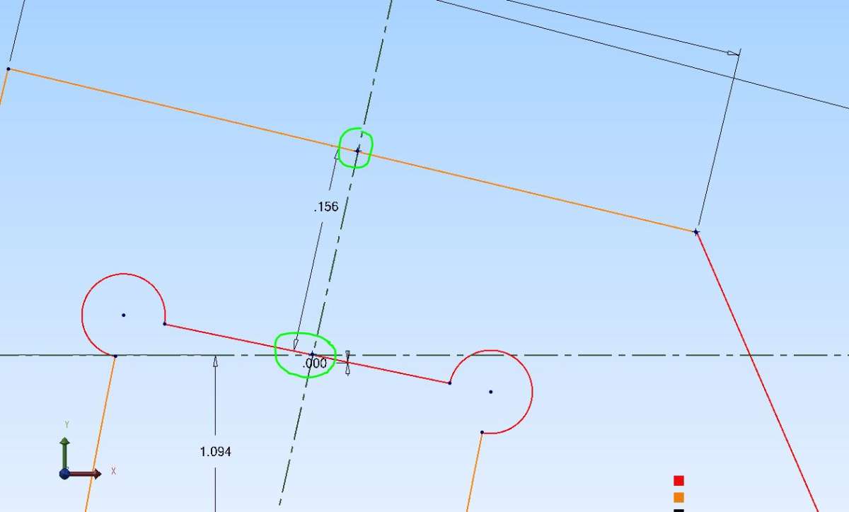
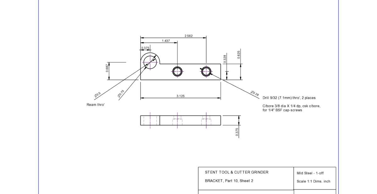
I found the fraction / decimal option and tried re-drawing this thing – about the hardest I’ve tried in Alibre.
I had to re-start it completely at least once, and had to make innumerable re-calculations, deletions and corrections, different attempts at single details, etc.
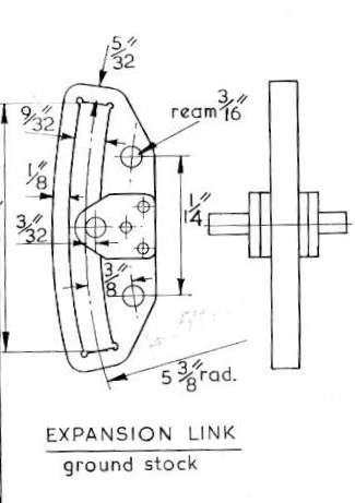
Whether the ends are meant to be parallel with the slot ends or radial would not matter in practice but drawing either form, to the specified thickness, was extremely difficult.
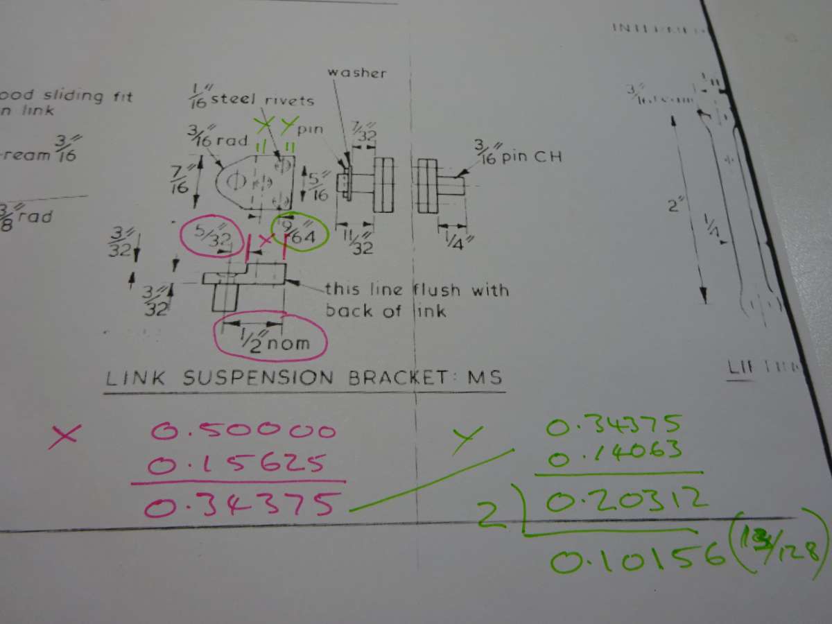
I plotted the axis of the suspension pin then located that straight back edge 0.500″ from there.
.
Eventually I had a 2D outline of the basic plate. I did not bother about rounded corners or those weeny holes of unknown size in the corners of the slot. Turning it into a 3D model meant several iterations to find and delete odd scraps of trimmed lines, and careful study of the drawing sheet to find the thickness, which is camouflaged by being on the drawing of the die-block.
.
Finally I tried to put those three rivet holes in it. I wanted to work these out myself, but where do I start?
Harris’ drawing omits to tell us, and I could not work them out. So I re-plotted the pin centre and put a circle on it, so I could plot that little step in the bracket to create a bounding rectangle for the rivets to live in by what looked about right.
It struck me that having to draw each of the bracket and the plate as separate Parts risks them not fitting together thanks to dimension errors in drawing their shared details, twice.
Only the pin was now visibly in the wrong place and I have no idea what I did wrong where.
Oh for Heaven’s sake! Start yet again…..
…… I closed the thing down instead.
.
It had taken me well over an hour to produce a faulty version of what anyone else would probably knock off all-correct in ten minutes.
Nigel Graham 2.


