Martin –
I understand your industrial practice but model-engineering drawings were never as demanding, and I am trying to translate one that breaks all your professional rules into ones I can use with my tools (errr…. and ability!). I want the parts right but my drawings don’t need follow trade formalities.
However, you do make the point that CAD can find missing dimensions – that’s more or less what I was trying to do but had somehow got lost on the way.
.
Jason, David –
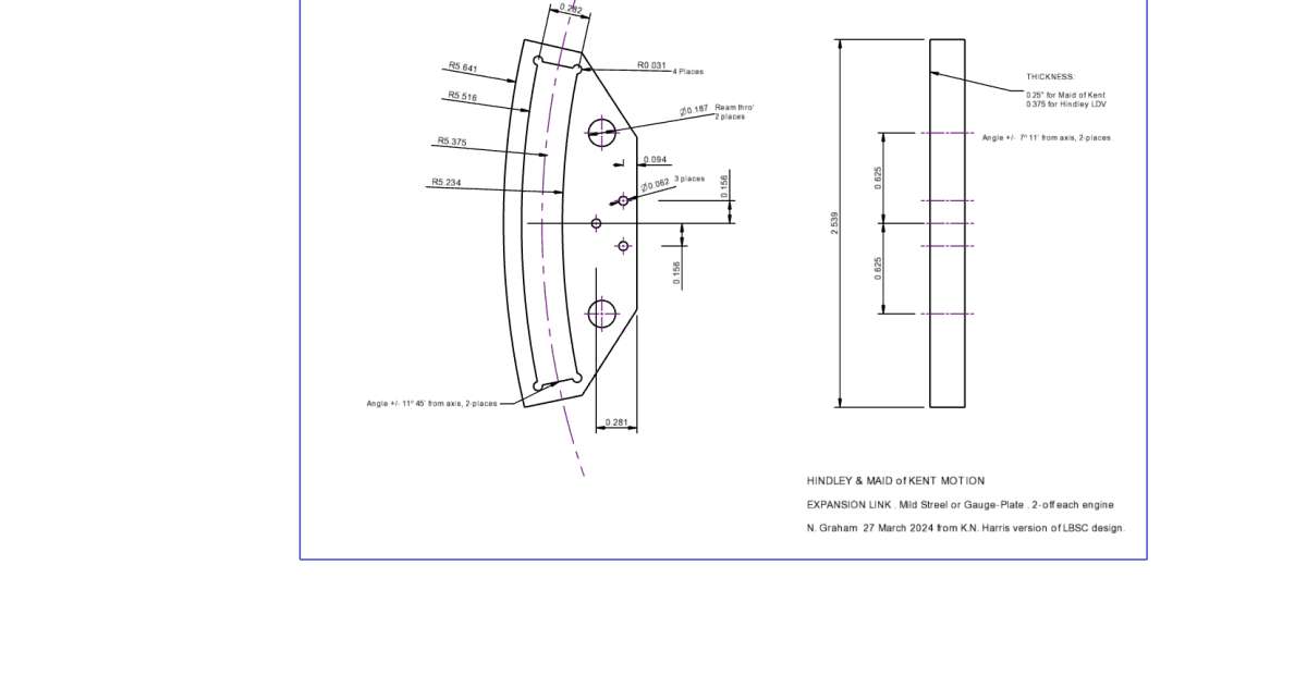
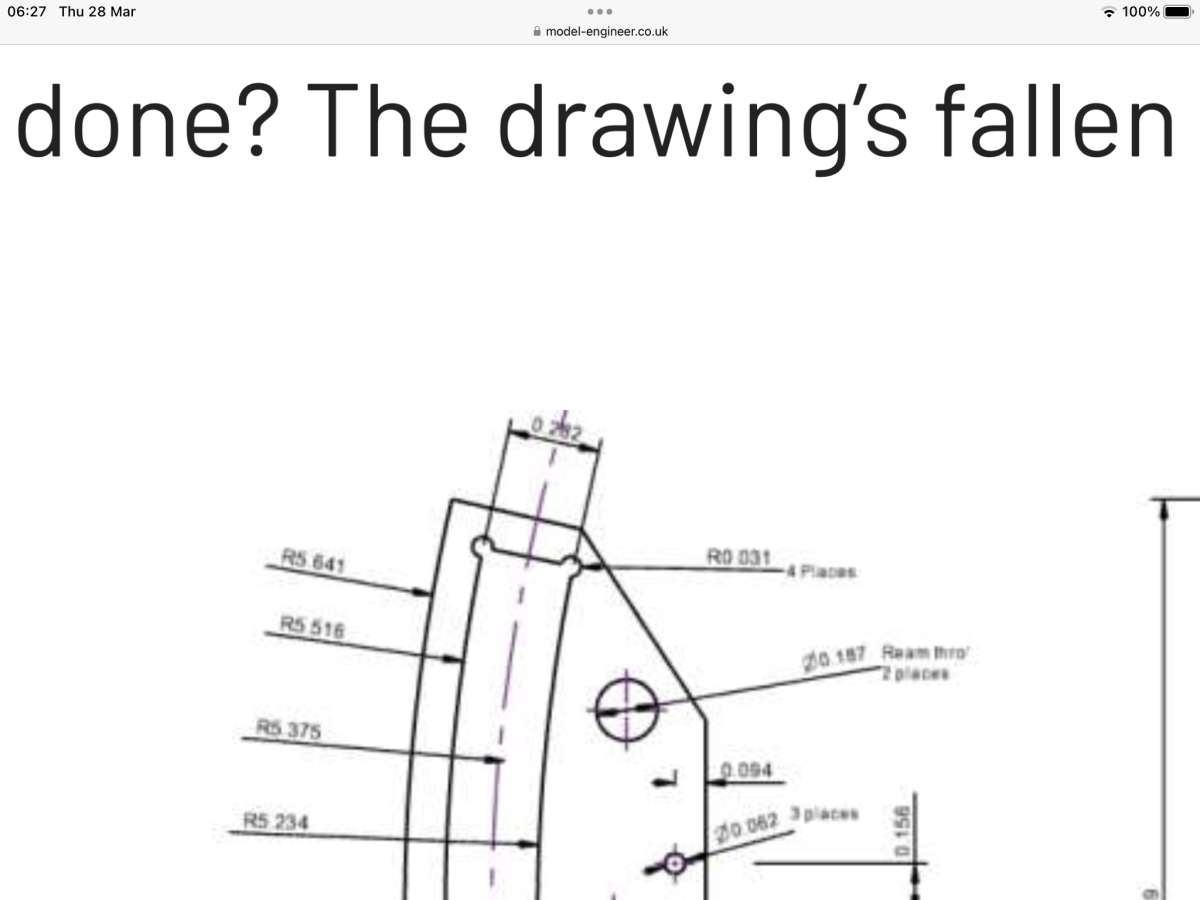
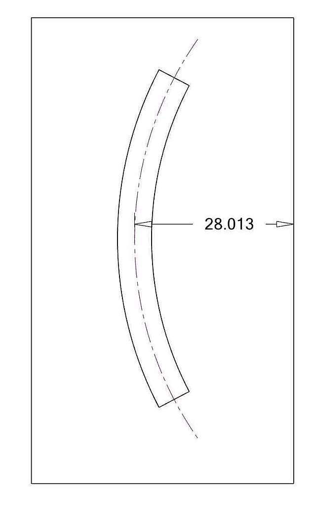
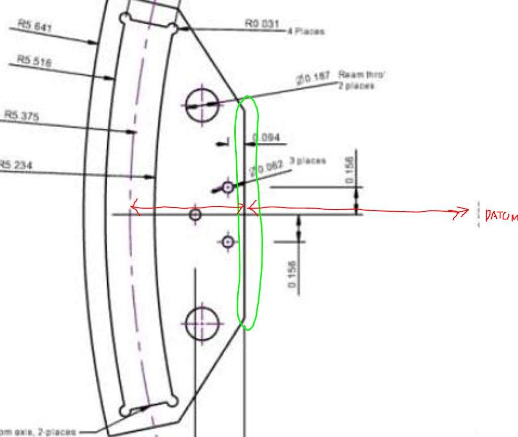
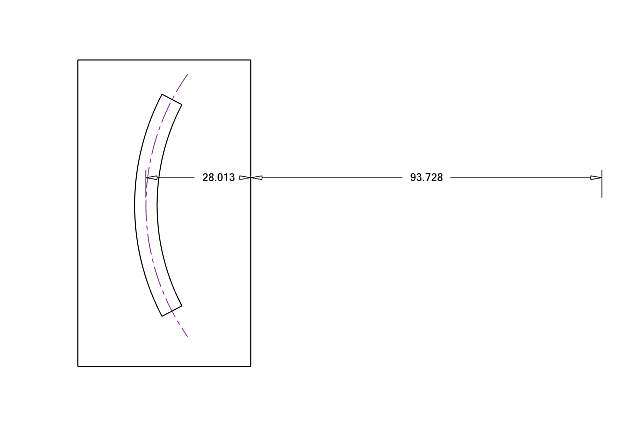
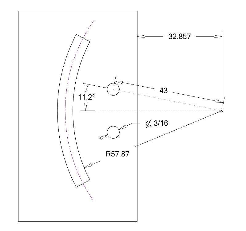
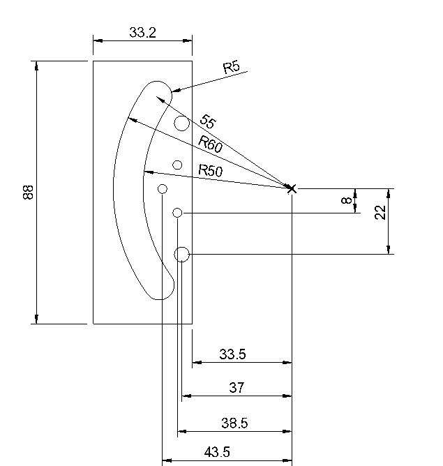
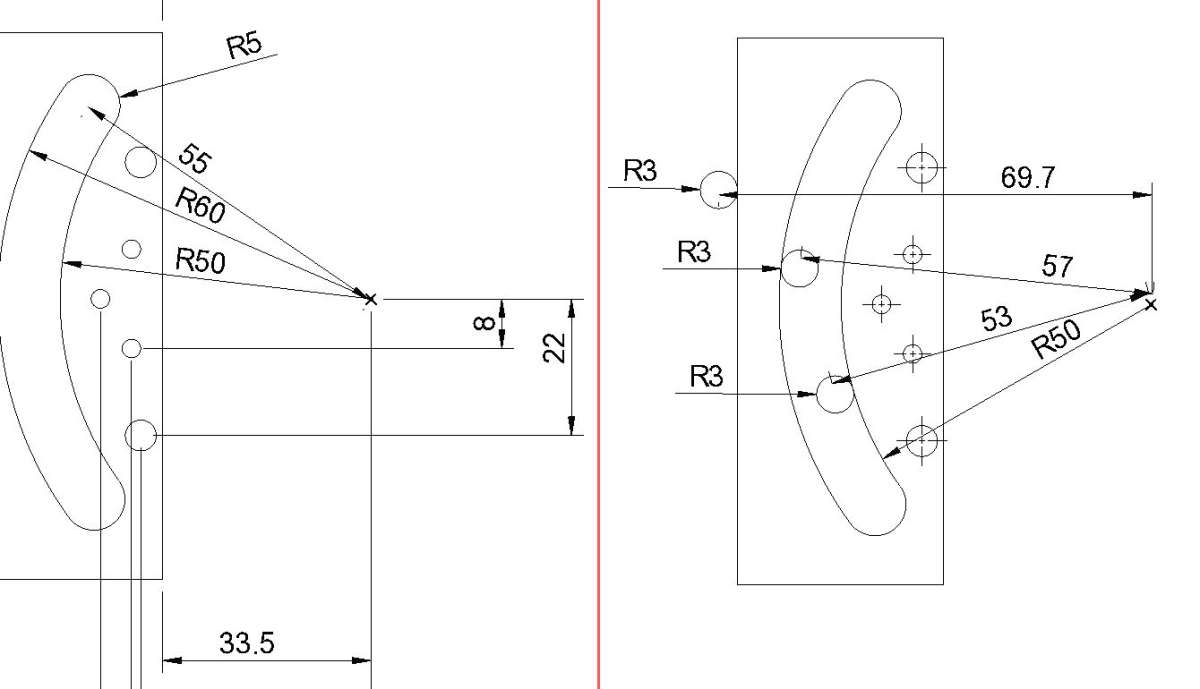
I am trying to verify my own version of an old drawing that is dimensioned from a centre not shown on the paper, and also has vulgar-fraction dimensions that sort of loop back on themselves.
.
To make it more fun, the drawings cover two versions. That link is on both sets but although those 3/16″ holes are shown by height and on a circular centre-line on both, the radius is omitted from one of the drawings! In both cases, the back edge is left un-dimensioned, as are the sloping ends, for the builder to work out as best he can.
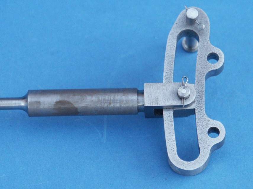
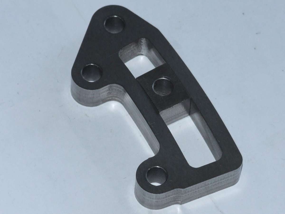
David – You say you are not clear what these links are for. That’s fine. Just treat them as drawing and making objects. After all, in most contract-engineering workshops you do not know what “Block A43a” or “Pt. No. ZXY5433” even go inside – and usually, are not meant to know. The three little holes hold a pair of brackets, on each side, with trunnions by which the link is suspended in the mechanism, and the trunnions need be a definite distance back from the centre of the slot.
.
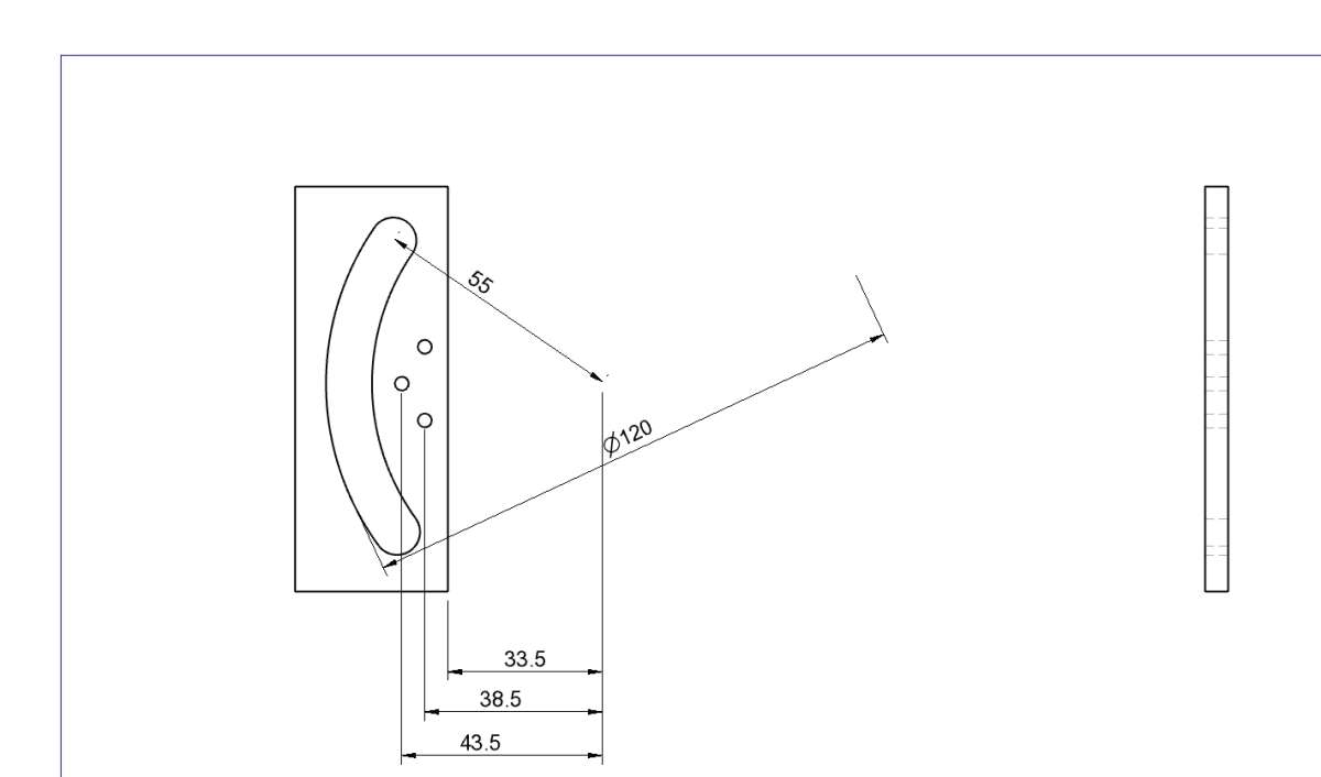
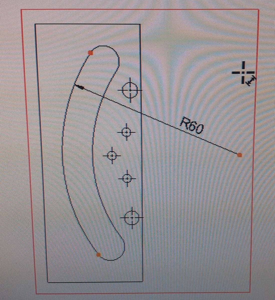
Aha! I have just opened the drawing in Alibre and wandered around the tool-bars a bit.
I have found the radial centre tool – it is off the “paper” at the scale I used. Plus those other dimension and other formatting menus.
I stripped the two height dimensions from the two small holes, and that revealed an extended centre-line that stops with orange dots just left of the slot centre-line, and just outside the outline to the right. So there is a CL intersection but I can’t dimension from it to anywhere else. The dimension wants to go from the dot instead.
.
I found the centre-line tool on the regular Drawing menu and the main tool-bar by exploring, and that obligingly put the centre-line on the slot.
The aspect I find hard is knowing exactly what elevation each coloured tile will produce. They are named but I am not sure what are Left, Right, etc. relatively to my Model image. Is the Preview image in the menu meant to show them? If so, how do you ask it to do that?
I have found the arrows next to that image flips it around but the caption stays as “front view”, and the preview does not reflect switching the coloured elevation buttons.
.
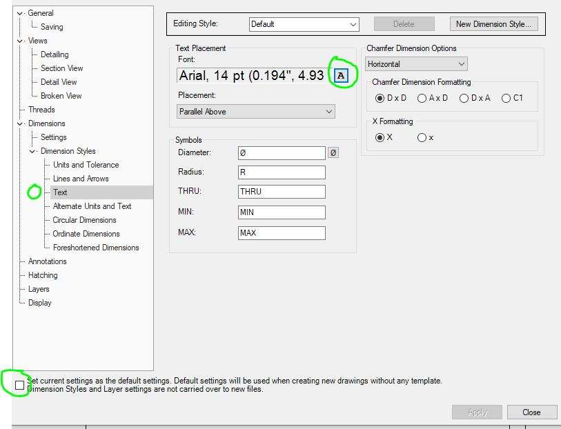
Thank you for the formatting tip. I was using the formatting tool-bar on the dimension menu itself, but do sometimes find it difficult to assess how large the characters will be on a print.
I don’t use the supplied templates because they give a lot of space to information necessary commercially, but not for model-engineering in our home workshops. I have tried to create my own, one in inches the other metric, with some limited success.
I did wonder if that drawing would be clear as a .jpg picture on here. I have not yet grasped the formatting subleties, Layers and so on, so the lines tend to all look the same and rather thin.
.
The original LBSC / Harris drawings specify “ground stock” for these links, but is that “precision ground mild steel” or “oil-hardening gauge-plate”? Probably the latter, without hardening and tempering it, but do wonder if a mild-steel link with a cast-iron or leaded-gunmetal die-block would be fine. The full-size engines probably used cast-iron for both, or a mild-steel link and cast-iron block.
………
The lack of an illustrated centre for all those link arcs may be due to this being, typically, a sheet full of very many components arranged to fit the paper.
You need study the assembly-drawings or any construction series carefully, or understand the machine generally, for the parts drawings do not show positively that all these arcs are concentric about a single point, nor where it is, only their radii.
This, LBSC’s 5″ gauge ‘Maid Of Kent’ design modified by Keith Harris, is not a beginner’s project, but how many tyros as LBSC called them, building much simpler locomotives really struggled thanks to drawings of similar standard?
Nigel Graham 2.


