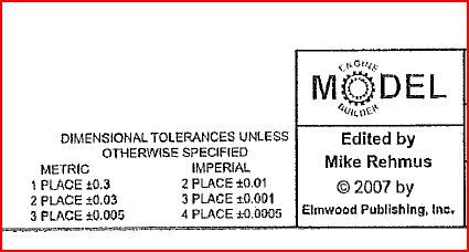
dim tolerances
dim tolerances
- This topic has 30 replies, 16 voices, and was last updated 2 March 2014 at 09:35 by
ANDY CAWLEY.
- Please log in to reply to this topic. Registering is free and easy using the links on the menu at the top of this page.
Latest Replies
Viewing 25 topics - 1 through 25 (of 25 total)
-
- Topic
- Voices
- Last Post
Viewing 25 topics - 1 through 25 (of 25 total)
Latest Issue
Newsletter Sign-up
Latest Replies
- Steam pressure using thermistor
- Supply company catalogues
- Machinery Handbook
- Chester DB10LB Lathe – Not starting
- Which type of single phase motors are best for constant use – power hacksaw
- James Coombes Drawing Error (or mine?)
- Flattening brass plates
- Stripped aluminum threads. Now what?
- Problem getting the right parameters on a VFD
- Damp proofing concrete floors


 then the implied tolerance is +/- 1/64" i.e a rule(er) measurement.

