“Digital Phase Converters” – Inverters for Multi-Motor Applications

Advert

“Digital Phase Converters” – Inverters for Multi-Motor Applications

Home Forums General Questions “Digital Phase Converters” – Inverters for Multi-Motor Applications

Viewing 20 posts - 26 through 45 (of 45 total)
  • Author
    Posts
  • #616885
    Clive Steer
    Participant
      @clivesteer55943

      Many VFD and especially the cheap ones have a simple bridge rectifier and reservoir capacitor front end to derive the DC link voltage of approx 330V which is used by switched transistors to produce the 3 phase output. On a single phase supply current is drawn from the supply over a fairly short period at the peaks of the sine wave. When loaded the link voltage droops and there is high ripple current in the reservoir capacitors which can limit the maximum power available. This can be acceptable for a VFD starting a motor softly but the high very high load presented by a DOL motor start droops the DC link to the point where the VFD detects an under voltage condition. Typically a DOL motor start draws between 5 and 10 time the max load current but only for a short time as the motor accelerates from being stationary. If for any reason such as additional machine inertia, viscous drag from cold lubricant or mechanical load then the high load can last for several seconds. So for DOL use an VFD would need to be rated at 10x the motor max power rating. Even if the VFD has an active front end to reduce the amount of DC link droop the need to rate it for the DOL surge load would make it prohibitively expensive.

      So the bottom line is that DOL starting is a challenging load for any supply and especially an active device such as a VFD or inverter

      A passive static converter using and auto transformer and capacitors has better overload resilience and one with an idler motor even better at managing the DOL surge load but are less popular because of their size and noise.

      There's no easy answer but the simplicity of DOL starting on a single phase supply leads to complexity elsewhere.

      CS

      Advert
      #616897
      Mark Rand
      Participant
        @markrand96270

        ^^^^^

        That isn't the case from my experience.

        #616934
        Clive Steer
        Participant
          @clivesteer55943

          Mark

          Can you tell us what your experience has been?

          CS

          #616940
          Robert Atkinson 2
          Participant
            @robertatkinson2

            A "proper" inverter will run a motor just fine but may need to be oversized a bit to cope with starting loads. Such an inverter should have some start up surge capacity. They also have (or should have) output filtering. A VFD has little or no surge capacity becuse:
            A. The load is not switched.
            and
            b. They have built in soft-start (speed / voltage ramp).

            Some of the converters / inverters being sold are actually VFDs which have been de-rated and have the parmeters set to allow load switching. I'm guessing this is includes setting the overloads higher than normal.
            They work but are not ideal and most of the ones I've seen advertised would require a lot of work to make a legal installation and a fair bit just to make them safe.

            The other issue with using a VFD type "converter" is that the output is the electronic equivalent of a Delta transformer or generator. This means there is no neutral connection and in almost every case the load must be balanced across the phases. Adding a Delta-Star transformer will provide a neutral but does not solve the load balance issue.

            There are lots of things that can be made to work but this does not mean that they are legal, safe or good design.

            Robert G8RPI.

            #616946
            noel shelley
            Participant
              @noelshelley55608

              There is always the option of generating your own 3Ph, petrol or diesel powered, at least then it will be REAL 3Ph, maybe not an option for many, just a thought ! Noel

              #616947
              Mark Rand
              Participant
                @markrand96270
                Posted by Clive Steer on 11/10/2022 16:38:24:

                Mark

                Can you tell us what your experience has been?

                CS

                Running Hardinge lathe, Beaver milling machine, J&S 1400 surface grinder and Wolf pedestal grinder over the last 12 years or so, all fed by a single VFD/inverter. Initially Danfoss, later Teco. with DOL starting, plug reversing, dual speed motor and multiple machines operating at the same times.

                Oh, and there isn't an issue with unbalanced loads. Inverters are constant voltage supplies, not constant current. I do have a neutral generating transformer, but in fact none of my machines and virtually no industrial machines need a 3ph 5 wire supply.

                Edited By Mark Rand on 11/10/2022 18:11:11

                #616958
                Anonymous
                  Posted by Jelly on 10/10/2022 11:27:34:

                  Every "VFD" I've ever used has had an integrated logic controller, with the motor drive electronics not directly controllable without interfacing through that logic controller…

                  No-one is suggesting that one would control the 3-phase bridge directly. On VFDs I have used the basic functions such as on/off, forward/reverse and frequency can be controlled from the front panel, via external components such as switches and potentiometers or from an external controller, usually via a comms link.

                  Conceptually the 3-phase control signals are simple. How the values are arrived at can be simple or complicated depending upon the control algorithm. Simple V/f control only needs a microcontroller but vector control ideally needs a DSP, preferably floating point to simplify the software.

                  Andrew

                  #616972
                  Robert Atkinson 2
                  Participant
                    @robertatkinson2

                    Mark,

                    I think that you have been lucky. The fact that your VFD seems to be rated to drive your full set of machines helps. If switching a single load the VFD must have enough overhead to start it. When you have other machines running their motors act as an energy reserve stabilising the VFD output. I guess your imbalance is less than 10% whidh is probably to small to notice.
                    How do you manage earthing and other safety requirements like RCDs?

                    Robert G8RPI.

                    #616977
                    Clive Steer
                    Participant
                      @clivesteer55943

                      Mark

                      I'd be interested to know what model of Danfoss and Tech VFD's you used so I can get some idea of the capability they have.

                      CS

                      #616984
                      Jelly
                      Participant
                        @jelly
                        Posted by noel shelley on 11/10/2022 17:41:20:

                        There is always the option of generating your own 3Ph, petrol or diesel powered, at least then it will be REAL 3Ph, maybe not an option for many, just a thought ! Noel

                        I did seriously consider that, there was a 7.5kVA unit that just went for £400 on eBay, but it had clearly had a very hard life… The only other one which is suitable is a 10kVA unit with low hours going for about a grand, so less economic.

                        Currently, a diesel genny would be *very* competitive with grid prices too.

                        Unfortunately I live in close proximity to my neighbours, and with the best will in the world, "silenced" diesel generators are still obnoxiously loud in close proximity.

                        #616987
                        Jelly
                        Participant
                          @jelly

                          My take away from this thread is that it's technically an option, but at my scale it would be difficult to find a suitable inverter commercially, and I should be very cautious of being sold a large VFD which has been reworked to fill that gap, but producing EM interference and not meeting appropriate safety standards.

                          In light of that, I will probably persue a second hand rotary phase converter on the basis of it previously working just fine.

                          #616992
                          Jelly
                          Participant
                            @jelly
                            Posted by Robert Atkinson 2 on 11/10/2022 17:00:07:

                            Some of the converters / inverters being sold are actually VFDs which have been de-rated and have the parmeters set to allow load switching. I'm guessing this is includes setting the overloads higher than normal.

                            1. They work but are not ideal and most of the ones I've seen advertised would require a lot of work to make a legal installation and a fair bit just to make them safe.

                            Robert G8RPI.

                            Out of curiosity what are the factors that you believe render these systems:

                            1. Unsafe
                            2. Non-compliant

                            I'm always just as interested to learn more about how NOT to do things for future reference, as to learn how to do something.

                            #617079
                            Robert Atkinson 2
                            Participant
                              @robertatkinson2

                              Jelly,

                              The unsafe bit comes in two areas,

                              1/ The units themselves are components and need to be put in a suitable enclosure with over-current protection etc. Without an enclosure many have exposed terminals (or covers that don't need a tool to remove), inadequate or no cable strain reliefs and they are generally not protected against dust etc.

                              2/ The equipment they are connected to wil have it's electrical safety based on it being connected to a conventional mains supply that is referenced to earth (even if neutral is connected). The output of a VFD is not normally referenced to ground. A VFD output typically has high frequency components that can affect filter components and cause leakage currents. They often have high voltage spikes that cn breakdown insulation.

                              For legality the big issue is interference (EMC /EMI). All VFDs need filtering. Some have filters on their mains inputs but it not common and may not be enough. They require careful grounding, often shielded cables and approriate connectors with 360 degree backshells. Even when the makes says they will meet emissions levels they will almost certainly mean industrial levels, if used in a residential area (technically just one home on the same substation or transformer feed) you have to meet the lower consumer equipment levels. From experience this can require double metallic cases, extra filters and special cables.
                              The filters cause another issue. Buy design they draw a large leakage current, well in excess of that allowed for consumer equipment. Often enough to trip a 30mA RCD. This can require a large and expensive transformer on the input. If you loose an earth connection the filters acn pas enough current to kill you even without a fault.
                              You can't wire a VFD output up to a wall standard wall socket because it does not have the protection required of a mains installation.

                              Just because you can hear your radio does not mean it is OK you relly could be affecting somone else. I once delt with a case where a piece of equipment with a 50Hz sinewave output generated by PWM like a VFD caused real interference to a ground approach radar on a RAF airfield. The radar operated on 10,000,000,000Hz and was completly wiped out by the interference. how could a 30kHz PWM making 50Hz cause that? It seemed unlikely even to me. It turned out to be harmonics. Mostly caused by the installer not using the prescribed cable layout but even with that corrected I had to design a special filter to get it down to an acceptable level.

                              Oh and another issue with VFD's generally even when properly installed is tht they can cause DC leakage currents in the mains supply. This current can saturate the current transformer in a RCD aor RCBO "earth leakage trip" on the household supply. Comminlly called "blinding" an RCD. There is no sign of this but it stops the RCD from working so a fault somewhere else in the houst that could cause a fire or electric shock that would normally cause the RCD to trip won't trip oit and this can have fatal results.

                              The RCDs most affected are "AC" types and are the most common. If you use a VFD connected to the domestic supply you should ensure that RCD(s) in the house are changed to ones not blinded by DC leakage (typically a type A but F or B may lso be suitable).

                              Robert G8RPI.

                              #617133
                              Anonymous

                                Posted by Robert Atkinson 2 on 12/10/2022 22:04:15:

                                …how could a 30kHz PWM making 50Hz cause that…

                                The spacing and number of harmonics are dependent upon pulse repetition rate and pulse width. How high the harmonics go, at a detectable level, is mainly controlled by the speed of the pulse edges. The faster the edge the higher the frequency of detectable harmonic.

                                Andrew

                                #617137
                                Robert Atkinson 2
                                Participant
                                  @robertatkinson2

                                  Hi Andrew,

                                  It was a rhetorical question…. I can't give details but the interfence wasn't getting in the front end at 10GHz.

                                  I have a comb generator that uses a fast diode to generate harmonics to at least 18GHz.

                                  Robert G8RPI.

                                  #617163
                                  Jelly
                                  Participant
                                    @jelly

                                    Thanks Robert,

                                    Very glad I asked, the electrical safety bits were mostly what I expected, although I hadn't realised that the voltage spikes were so severe as to exceed the insulation breakdown voltage in some cases.

                                    Nor do I think I'd ever had an explanation of why type AC RCB/RCBO's are unsuitable for circuits which are liable to DC injection either… even though I am aware that good practice is to use Type B when you have PWM equipment in the circuit.

                                    The EMI aspect however I was entirely blind to, and the issue of leakage current from filters too (although it explains why 100mA RCD's are often recommended by sellers, even though they're only suitable for wiring protection, and not personal protection) so that's very interesting.

                                    #617213
                                    Robert Atkinson 2
                                    Participant
                                      @robertatkinson2

                                      It is also against BS 7671 "Requirements For Electrical Installations" for a socket outlet of 32A or less not to be protected by a 30mA RCD (there is an exemption for single socket if a safety assesment is carried out).

                                      Robert G8RPI

                                      #617234
                                      SillyOldDuffer
                                      Moderator
                                        @sillyoldduffer

                                        I've got a couple of Software Defined Radios with waterfall displays that show radio signals over a considerable bandwidth, not just one station at a time.

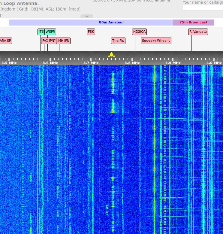
                                        This image shows what the 80metre amateur band (3.5 to 3.8MHz) looks like at a low interference location (near Weston Super Mare). The blue background is background noise, while the vertical lines are signals. The signals are colour coded to show strength, light blue weak, yellow middling, red strong. As only one signal has any red in it, even moderate interference causes a wipeout.

                                        wsm_80m.jpg

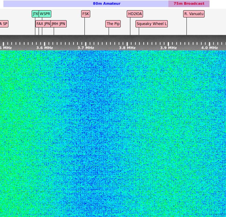
                                        Next picture is me using the same type of receiver, with a low back garden antenna, with my lathe running:

                                        sod80m.jpg

                                        As can be seen, the band is full of noise, and no signals can be seen. It's a blizzard of electronic muck.

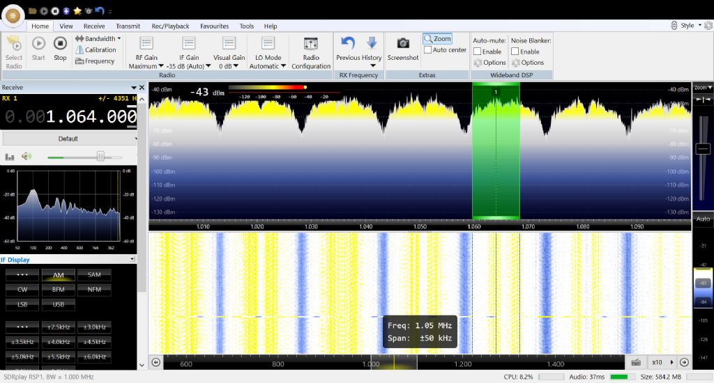
                                        Worse, the interference spreads over much more than the 80metre band. Next picture shows strong interference from below Long Wave reaching up to about 20MHz, weakening rapidly above that. (This particular VFD doesn't cause obvious bother at VHF or UHF – as far as my equipment can tell.)

                                        sod_sw_lathe.jpg

                                        An SDR positioned next to the lathe shows multiple spikes, all strong enough to blot out AM broadcasts.

                                        sc_cable.jpg

                                        Root cause is that VFDs and other types of electronic supply work by rapid switching, and, as Andrew said, fast rise times cause harmonics. It doesn't help that power supply electronics aren't frequency stabilised, so the fundamental and harmonics wander about, smearing interference more widely.

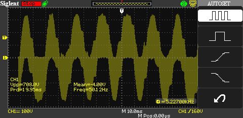
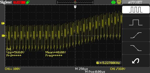
                                        An oscilloscope view of the VFD output shows it's a broad approximation of a sine wave, far from pure. The oscilloscope suggests the waveform's frequency is 50.14Hz and 5.23kHz.

                                        p4wv.jpg

                                        Zooming in shows that this 3-phase VFDs 'sine wave' is actually made up of pulses:

                                        p1wv.jpg

                                        The only good news is that interference at low frequencies tends to weaken rapidly with distance, it has the potential to annoy neighbours, especially if spikes are injected into the mains and travel down the street along power cables.

                                        Which reminds me, I've been intending to fit a filter for a few years now and never not got round to it!

                                        blush

                                        Dave

                                        #617237
                                        John Haine
                                        Participant
                                          @johnhaine32865

                                          As a matter of interest Dave, what SDR hardware are you using please?

                                          #617315
                                          Robert Atkinson 2
                                          Participant
                                            @robertatkinson2

                                            Connecting test eqipment to the mains or the output of a VFD is inherently dangerous. Dave, I assume you know this and used appropriate equipment.
                                            If anyone is thinking of doing this, it is not safe to use a standard 'scope and probes. You can damage the equipment or yourself. If you don't undstand why, you should not try it.

                                            Robert G8RPI.

                                          Viewing 20 posts - 26 through 45 (of 45 total)
                                          • Please log in to reply to this topic. Registering is free and easy using the links on the menu at the top of this page.

                                          Advert

                                          Latest Replies

                                          Home Forums General Questions Topics

                                          Viewing 25 topics - 1 through 25 (of 25 total)
                                          Viewing 25 topics - 1 through 25 (of 25 total)

                                          View full reply list.

                                          Advert

                                          Newsletter Sign-up