Difficulty Operating Solenoids with an Arduino Uno

Advert

Difficulty Operating Solenoids with an Arduino Uno

Home Forums Electronics in the Workshop Difficulty Operating Solenoids with an Arduino Uno

Viewing 25 posts - 1 through 25 (of 53 total)
  • Author
    Posts
  • #516013
    James Alford
    Participant
      @jamesalford67616

      I wonder whether anyone can help?

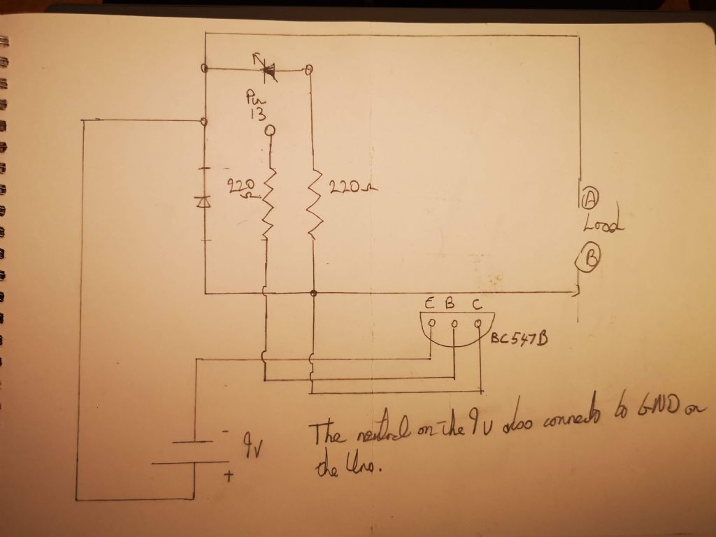
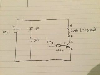
      I wish to operate some 6 – 12v solenoids with an Arduino Uno. I have written the code and built a circuit Circuitwhich uses transistors and an additional power supply to avoid overloading the Uno.

      The Uno is powered through the power jack using a transformer. The additional power is supplied by a 9v battery which has its negative lead connected to the GND pin on the Uno. I have wired up the circuit in the attached diagram. The LED shown in the circuit is there simply to show that the circuit is working.

      Everything works as expected except that the transistor is passing only 1.5v to the output terminals shown as A and B in the diagram. However, I was anticipating in the order of 9v. Either I have misunderstood what this circuit is meant to do or I have made an error in the design.

      Can anyone advise what I have done wrong, please, and how I can get 9v at the output?

      Regards,

      James.

      Advert
      #32161
      James Alford
      Participant
        @jamesalford67616
        #516015
        duncan webster 1
        Participant
          @duncanwebster1

          Your transistor has the load between 9v and collector. There should be 9v at terminal A at all times With the solenoid connected between A&B and pin 13 high, the transistor should conduct and the voltage at B should be very low. With pin 13 low, the transistor will not conduct and so the voltage at B will be 9v.

          I reckon you'e got the LED wrong way round

          #516019
          Stuart Smith 5
          Participant
            @stuartsmith5

            Edited By Stuart Smith 5 on 28/12/2020 23:31:32

            Edited By Stuart Smith 5 on 28/12/2020 23:31:55

            Edited By Stuart Smith 5 on 28/12/2020 23:35:39

            #516031
            AJAX
            Participant
              @ajax
              Posted by Stuart Smith 5 on 28/12/2020 23:29:04:

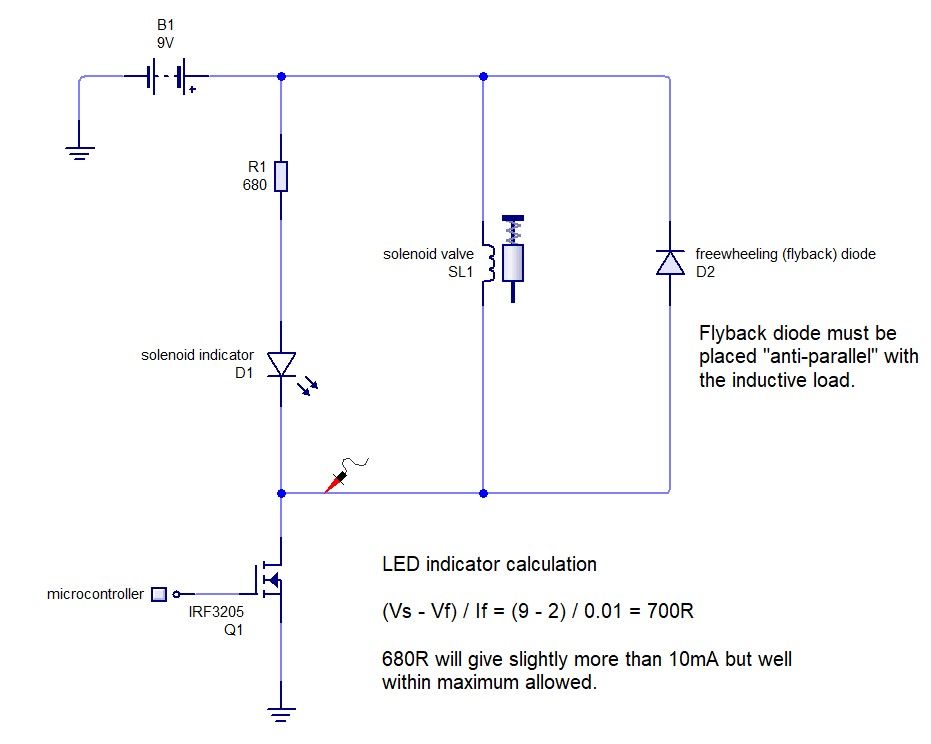
              You have some of the connections wrong. This should work:

              1eb69bc8-e1a5-47f3-a216-19bd37ae04de.jpeg

              With Arduino pin 13 output high, the solenoid coil should be energised.

              I think!

              Stuart

              Edited By Stuart Smith 5 on 28/12/2020 23:31:32

              Edited By Stuart Smith 5 on 28/12/2020 23:31:55

              I believe that James wants the LED to act as an indicator for the solenoid (LED on when the coil is energised). The LED therefore needs to be placed in parallel (forward biased) with the solenoid load.

              The solenoid is an inductive load and the circuit should be protected with a freewheeling or flyback diode. 1N4001 in reverse bias with the solenoid would be fine.

              The use of low-side switching where the load is placed on the collector side of the the transistor "switch" is correct for this application.

              Assuming pin 13 outputs a logic high of about 5V and Vbe 0.7V this will draw about 20 mA base current. BC547 is a small signal transistor and not ideally suited to switching solenoids and you'd have to be careful of the expected collector current.

              For a switching application I would suggest use of a logic-level N-channel MOSFET. Off the top of my head, an IRF3205 would be fine and would be able to handle substantially more current than you will switch. The MOSFET requires no resistor on the gate. Any charge on the gate due to gate capacitance would discharge (sink) back to pin 13 during logic low.

              Do you need a circuit drawn?

              Brian

              #516036
              AJAX
              Participant
                @ajax

                Another point, most standard 5mm red LEDs have a maximum forward current of about 15 – 20 mA.

                Check the data sheet if you have one.

                If not, choose a current limiting resistor that limits current to about 10 mA. You can assume Vf is about 2V.

                #516039
                AJAX
                Participant
                  @ajax

                  solenoid.jpg

                  #516077
                  SillyOldDuffer
                  Moderator
                    @sillyoldduffer

                    The switching part of James' circuit looks OK to me, but a few things to try:

                    • C and E may be the wrong way round on the BC547B? According to the datasheet, the transistor lead order is C B E, not E B C.
                    • Confirm the source code in setup() makes the pin an Output with pinmode( 13, OUTPUT ); If the pin isn't declared OUTPUT, it signals with insufficient oomph to switch a transistor.
                    • Use any other pin rather than 13! Pin 13 powers the Arduino's on board LED, which might matter in this application because the built-in LED absorbs current otherwise needed for switching the BC547B. (It should work as is, but…) AJAX's circuit avoids this problem with an IRF3205 FET. These are switched by voltage, requiring hardly any power, but NPN transistors are switched by current so you have to keep an eye on pin and chip maximum ratings.
                    • Don't measure from A to B. Instead connect the solenoid or a 1k test resistor and measure volts from B to battery minus. B should float at 9V until the transistor is switched on, at which point volts at B should drop to near zero. Provided the solenoid is a 9V type drawing less than 100mA, it should work.

                    Dave

                    #516098
                    James Alford
                    Participant
                      @jamesalford67616

                      Good morning and thank you for the replies and advice.

                      I have had a look and a play with the circuit, testing it as suggested by Dave. Everything operates as I want it to do, with the solenoid pulsing each second. The circuit is for a clock and the other pins are programmed for the minute, hour, day and so forth. These all trigger the solenoid as planned.

                      My puzzlement was that I could only read 1.5v across A and B with no load attached. Perhaps, most likely, the problem is my weak knowledge of electronics, rather than an actual problem.

                      As a round-up of the current position:

                      • Yes. I am using the LED to flash at the same time that the relay operates as a visual indicator.
                      • The relay is operating as expected on all programmed pins, including 13.
                      • I removed the LED to see what would happen and nothing changed.
                      • Testing as Dave suggests shows 9v until the transistor switches, when the voltage drops by about 1.5v. However, the "on" pulse is very short, so it may be that my AVO cannot respond quickly enough to show the true fall in voltage.
                      • The solenoid in use is meant to draw 0.25a, but I am measuring it at 25ma.

                      My questions now are:

                      • Is my cicruit likely to overload the Uno? The are six relays in total, but they operate at marginally different times.
                      • Is there a need to change the transistor, given the current and the voltage in question? If so, is there one which I could use as a direct replacement in the existing curcuit? I have six in total.

                      Thank you.

                      James.

                      Would changing the transistor

                      #516102
                      Bazyle
                      Participant
                        @bazyle

                        I haven't studied the above in detail but bear in mind with similar small controllers that they are often not designed to source much current from their output pins so while they can often sink currnet to drive a LED they can't provide much current to turn on a transistor. Check the specs.

                        Also note the way Ajax has drawn the diagram. There is a convention in electronics for the way you draw things that makes it far far easier to understand. I have encountered unfortunate HNC students totally failing because their idiot teachers did not follow the conventions so their pupils were at a massive disadvantage. When shown the conventional layout comprehension increased tenfold.

                        #516107
                        John Haine
                        Participant
                          @johnhaine32865

                          I have an Arduino Nano sourcing 15 mA driving a small coil on the clock on my desk, and about 10 mA to drive the movement so there should be no drive current issue into the base of the transistor.

                          As Bazyle says the way the circuit is drawn is rather bizarre which makes it hard to read and comment.

                          We can't comment on the transistor choice without knowing more about the solenoids, in particular their resistance. But mosfets as suggested above would be the preferred choice these days as they don't need any current to drive them (to speak of). Ah, you said it's meant to draw 250 mA, but that would be the static current – how are you measuring your 25 mA, with an AVO on the pulse? See comment below.

                          Are you using an "analogue" AVO and how long is the pulse? Why not just make it longer for test purposes? Whether a "real" AVO or a digital variant, they have a time constant of half a second or so so that would easily explain the reduced reading

                          #516119
                          SillyOldDuffer
                          Moderator
                            @sillyoldduffer
                            Posted by James Alford on 29/12/2020 11:17:34:

                            • Testing as Dave suggests shows 9v until the transistor switches, when the voltage drops by about 1.5v. However, the "on" pulse is very short, so it may be that my AVO cannot respond quickly enough to show the true fall in voltage.
                            • The solenoid in use is meant to draw 0.25a, but I am measuring it at 25ma.

                            My questions now are:

                            • Is my cicruit likely to overload the Uno? The are six relays in total, but they operate at marginally different times.
                            • Is there a need to change the transistor, given the current and the voltage in question? If so, is there one which I could use as a direct replacement in the existing curcuit? I have six in total.

                            The maximum output from an individual Uno pin is 40mA (but never exceed 30mA because they go pop!), and the total current taken by all output pins must be less than 100mA. With a 220ohm resistor between pin 13 and the transistor base, the max current from I=V/R will be 23mA, or 128mA in total if all six relays are operated at the same time. No problem doing 4 relays together, but all 6 is pushing it. Increasing the 220 ohm resistor to 330ohm would add a safety margin.

                            AJAX mentioned the BC547B being a small signal transistor (max 100mA) isn't ideal for a solenoid, and it's certainly too small for a 0.25A device! I'd substitute a switching transistor like the 2N2222A, which is good for 0.8A. Same circuit, just a beefier transistor. (AJAX's FET is good for over 100A, and needs less drive current!)

                            The pulse length may need to be increased. Solenoids take time to react, and for the same reason an Avo needle is too slow to follow a fast pulse. Best that can be said if your pulse is less than, say 0.5s, is that the current drawn by the solenoid is at least 25mA, probably much more. Not a criticism of Avo's – most basic meters take a few seconds to settle, which is why an oscilloscope is so useful.

                            The A-B puzzlement is natural enough! It's because pulling B down to ground with the transistor causes current to to flow whereas the meter measures volts. Measuring B to ground allows a voltmeter to clearly register the circuit is working because it swings from 9V to Zero. Volts from A to B depends on load resistance so you get non-obvious readings.

                            Dave

                            #516120
                            Anonymous

                              Posted by AJAX on 28/12/2020 23:49:19:

                              For a switching application I would suggest use of a logic-level N-channel MOSFET. Off the top of my head, an IRF3205 would be fine………………………

                              The IRF3205 doesn't look like a logic level MOSFET according to the datasheet I downloaded? A simple NPN transistor, such as the FMMT491, will work fine. For bipolars it's good practice to have a resistor from base to emitter, say 10k. Same for a MOSFET, say 100k from gate to source. When processors power up most GPIO pins come up as inputs by default. The purpose of the resistors is to ensure that the transistor is off when the base/gate is essentially floating.

                              I'd agree with John Haine that an Avo is not the best choice of meter; a 'scope would be ideal. It's not true to say that MOSFETs need no drive current. They can require substantial current, albeit for a short time. On the datasheet gate charge is the key parameter. For digital ICs the majority of the current consumption is due to charging and discharging the gates during switching.

                              Andrew

                              #516122
                              AJAX
                              Participant
                                @ajax
                                Posted by SillyOldDuffer on 29/12/2020 09:52:57:


                                • Confirm the source code in setup() makes the pin an Output with pinmode( 13, OUTPUT ); If the pin isn't declared OUTPUT, it signals with insufficient oomph to switch a transistor.
                                • Use any other pin rather than 13! Pin 13 powers the Arduino's on board LED, which might matter in this application because the built-in LED absorbs current otherwise needed for switching the BC547B. (It should work as is, but…) AJAX's circuit avoids this problem with an IRF3205 FET. These are switched by voltage, requiring hardly any power, but NPN transistors are switched by current so you have to keep an eye on pin and chip maximum ratings.

                                Port bits ("pins" ) used as outputs must be declared as outputs. Outputs don't have extra "oomph". Inputs configured with internal pullups may be a cause of confusion?

                                Current is not "absorbed". I realise this is an attempt to explain the situation using layman's terms, but it may be useful for the unaware to read about charge conservation and Kirchoff's current law (KCL).

                                An ideal MOSFET ("ideal" doesn't really exist) has an infinite gate impedance and will not draw any current. A real world MOSFET such as the IRF3205 has a very high gate impedance and small gate capacitance and so any transitory current (to charge the gate) can be ignored.

                                In some applications it may be necessary to add a resistor between the microcontroller pin and the MOSFET gate, but in this application it is not required.

                                Edited By AJAX on 29/12/2020 12:36:05

                                #516125
                                AJAX
                                Participant
                                  @ajax

                                  The maximum output from an individual Uno pin is 40mA (but never exceed 30mA because they go pop!), and the total current taken by all output pins must be less than 100mA. With a 220ohm resistor between pin 13 and the transistor base, the max current from I=V/R will be 23mA, or 128mA in total if all six relays are operated at the same time. No problem doing 4 relays together, but all 6 is pushing it. Increasing the 220 ohm resistor to 330ohm would add a safety margin.

                                  AJAX mentioned the BC547B being a small signal transistor (max 100mA) isn't ideal for a solenoid, and it's certainly too small for a 0.25A device! I'd substitute a switching transistor like the 2N2222A, which is good for 0.8A. Same circuit, just a beefier transistor. (AJAX's FET is good for over 100A, and needs less drive current!)


                                  Check the datasheet for the 2N2222A – https://www.farnell.com/datasheets/296640.pdf

                                  Ic (max) = 800 mA

                                  This is an absolute maximum rating.

                                  The suggested MOSFET is a voltage operated device and for most purposes can be assumed to draw no current on the gate input. As you say, it is capable of switching a large current but it can also be used to switch a very small current too. RDS(on) is very low, only 8 mOhm making it good for power applications.

                                  https://www.digchip.com/datasheets/parts/datasheet/232/IRF3205-pdf.php

                                  Edited By AJAX on 29/12/2020 12:46:12

                                  #516129
                                  AJAX
                                  Participant
                                    @ajax
                                    Posted by Andrew Johnston on 29/12/2020 12:31:48:

                                    Posted by AJAX on 28/12/2020 23:49:19:

                                    For a switching application I would suggest use of a logic-level N-channel MOSFET. Off the top of my head, an IRF3205 would be fine………………………

                                    The IRF3205 doesn't look like a logic level MOSFET according to the datasheet I downloaded? A simple NPN transistor, such as the FMMT491, will work fine. For bipolars it's good practice to have a resistor from base to emitter, say 10k. Same for a MOSFET, say 100k from gate to source. When processors power up most GPIO pins come up as inputs by default. The purpose of the resistors is to ensure that the transistor is off when the base/gate is essentially floating.

                                    I'd agree with John Haine that an Avo is not the best choice of meter; a 'scope would be ideal. It's not true to say that MOSFETs need no drive current. They can require substantial current, albeit for a short time. On the datasheet gate charge is the key parameter. For digital ICs the majority of the current consumption is due to charging and discharging the gates during switching.

                                    Andrew

                                    Thanks for making me check the datasheet.

                                    https://www.digchip.com/datasheets/parts/datasheet/232/IRF3205-pdf.php

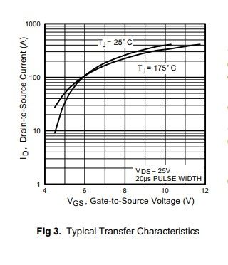
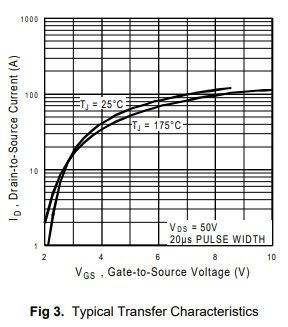
                                    Fig 3. Typical Transfer Characteristics indicates a drain-source current of about 50A with a 5V logic signal from the microcontroller. It may not be a true logic level MOSFET but should be fine for this application.

                                     VGS(th) Gate Threshold Voltage 2.0 ––– 4.0 V VDS = VGS, ID = 250µA

                                    #516130
                                    AJAX
                                    Participant
                                      @ajax
                                      #516132
                                      AJAX
                                      Participant
                                        @ajax

                                        IRL540N is a logic level MOSFET that may suit.

                                        https://docs.rs-online.com/8d29/0900766b80028e3a.pdf

                                        irl540n.jpg

                                        Edited By AJAX on 29/12/2020 13:06:19

                                        #516134
                                        AJAX
                                        Participant
                                          @ajax
                                          Posted by James Alford on 29/12/2020 11:17:34:

                                          My questions now are:

                                          • Is my cicruit likely to overload the Uno? The are six relays in total, but they operate at marginally different times.
                                          • Is there a need to change the transistor, given the current and the voltage in question? If so, is there one which I could use as a direct replacement in the existing curcuit? I have six in total.

                                          Thank you.

                                          James.

                                          James,

                                          I have only just read your updated question.

                                          Short answer – don't use a transistor. Don't use a MOSFET. Use a Darlington array (ULN2803)

                                          "The ULN2803A device is a 50 V, 500 mA Darlington transistor array. The device consists of eight NPN Darlington pairs that feature high-voltage outputs with common-cathode clamp diodes for switching inductive loads. The collector-current rating of each Darlington pair is 500 mA. The Darlington pairs may be connected in parallel for higher current capability. Applications include relay drivers, hammer drivers, lamp drivers, display drivers (LED and gas discharge), line drivers, and logic buffers. The ULN2803A device has a 2.7-kΩ series base resistor for each Darlington pair for operation directly with TTL or 5-V CMOS devices. "

                                          datasheet

                                          Note that base resistors are in the package so you don't need to add resistors in-line with the microcontroller outputs. You should make use of the internal diodes to clamp any inductive spikes from the loads.

                                          Brian

                                          #516142
                                          SillyOldDuffer
                                          Moderator
                                            @sillyoldduffer
                                            Posted by AJAX on 29/12/2020 12:35:37:

                                            Posted by SillyOldDuffer on 29/12/2020 09:52:57:

                                            • Confirm the source code in setup() makes the pin an Output with pinmode( 13, OUTPUT ); If the pin isn't declared OUTPUT, it signals with insufficient oomph to switch a transistor.
                                            • Use any other pin rather than 13! Pin 13 powers the Arduino's on board LED, which might matter in this application because the built-in LED absorbs current otherwise needed for switching the BC547B. (It should work as is, but…) AJAX's circuit avoids this problem with an IRF3205 FET. These are switched by voltage, requiring hardly any power, but NPN transistors are switched by current so you have to keep an eye on pin and chip maximum ratings.

                                            Port bits ("pins" ) used as outputs must be declared as outputs. Outputs don't have extra "oomph". Inputs configured with internal pullups may be a cause of confusion?

                                            Current is not "absorbed". I realise this is an attempt to explain the situation using layman's terms, but it may be useful for the unaware to read about charge conservation and Kirchoff's current law (KCL).

                                            An ideal MOSFET ("ideal" doesn't really exist) has an infinite gate impedance and will not draw any current. A real world MOSFET such as the IRF3205 has a very high gate impedance and small gate capacitance and so any transitory current (to charge the gate) can be ignored.

                                            In some applications it may be necessary to add a resistor between the microcontroller pin and the MOSFET gate, but in this application it is not required.

                                            Someone hold my coat – it's another violent agreement!

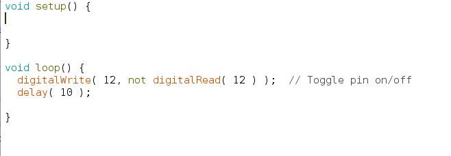
                                            Have you tested what happens when an Arduino pin isn't declared to be an output correctly? I mentioned it because it's a common coding mistake causing peculiar results. Try this program:

                                            nooutputcode.jpg

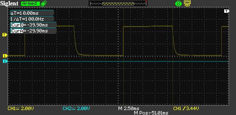
                                            Code compiles OK and an oscilloscope shows the expected waveform. But that curvy falling edge is odd:

                                            nooutputwaveform.jpg

                                            Recompiling the same program with pin13 rather than 12 produces no output because the LED and resistor 'absorb' the ghost. (Kirchoff is dead…)

                                            This version with OUTPUT enabled works correctly on both pins:

                                            withoutputcode.jpg

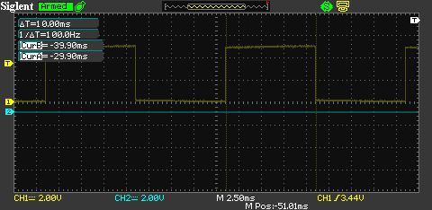
                                            And the waveform now has a proper sharp falling edge.

                                            withoutput.jpg

                                            I think the ghost appears when the pin's output transistor isn't enabled because there's enough leakage for a high impedance scope to see volts. But there's no oomph, sorry current, behind it. The output looks OK and might drive a high-impedance load, but is highly likely to cause odd symptoms!

                                            True a MOSFET needs no resistor on the gate, but having one does no harm either. Isn't a 2N2222A man enough for this application? The solenoid is 0.25A and the transistor is max 0.8A.

                                            Dave

                                            #516146
                                            James Alford
                                            Participant
                                              @jamesalford67616

                                              Just quickly.

                                              I have a genuine AVO. I do not have access to an oscilloscope, sadly. The pulse duration was chosen fairly randomly and can be extended. The will not all operate at the same time. They are programmed to operate sequentially.

                                              Scarily, I did electronics as part of my telephony apprenticeship, but it was theoretical and yonks ago.

                                              James.

                                              Edited By James Alford on 29/12/2020 14:19:16

                                              Edited By James Alford on 29/12/2020 14:21:33

                                              #516215
                                              duncan webster 1
                                              Participant
                                                @duncanwebster1

                                                If you're going to get into electronics, treat yourself to a Digital MultiMeter. Using a low impedance AVO will give rise to all sorts of confusion, because putting the meter in circuit changes the impedance of whatever you've put it across.

                                                My choice of transistor would be BC441, but only because I've got some. It claims to be good for 1A.

                                                #516228
                                                Peter G. Shaw
                                                Participant
                                                  @peterg-shaw75338

                                                  Don't get a digital multimeter! They are cheap and readily available for a reason – easy to manufacture whereas an Avo is a precision instrument and therefore rather more expensive.

                                                  Stick a digital on a varying waveform, and you will be unable to read it because the display will be flickering up and down. An AVO, or indeed any reasonable analogue meter will rapidly steady on a reading, ok the needle may oscillate rapidly, but you will have a much better idea of the voltages.

                                                  In respect of the impedance, an Avo, if my memory serves correct, will be using its 10V range with the battery being 9V. Thus the internal resistance of the Avo will be of the order of 200Kohms (10v at 20Kohms per volt), and I would suggest that 200K is effectively negligible in this context. Even measuring 1.5V will require the 2.5V range, and again at 20Kohms per volt, the Avo internal resistance will be 50Kohms, sufficiently large enough to be negligible in this circuit.

                                                  Finally, consider the so-called accuracy of a digital – say 3 & half digits plus or minus 1 digit or something similar. But lets not get bogged down in this – just think of the tolerance of the resistors being used in the circuit plus or minus 1% if you are lucky. More likely 2% or even 5%. Which means that the so-called accuracy of a digital is blown straight out of the water due to the tolerance of the components.To explain a bit further, suppose you have two 220 ohm resistors in series across the 9V battery. In theory, the voltage at the junction should be 4.5v – provided both resistors are exactly equal. If one is slightly high, and the other slightly low, then the voltage at the junction will not be 4,5V., indeed with 1% tolerance resistors, the centre voltage could correctly be anything between 4.2v to 4.8v. So, why bother measuring a voltage to say 2 or more decimal places?

                                                  Andrew talks about good practice to have a resistor between base and emitter. He is quite correct and suggests a value of 10K. Fair enough, but in a lot of instances, a much higher value would be just as satisfactory. Many years ago, my then manager "lumbered" me with repairing some digital display units of which he had arranged for a local firm to build 130 units. The agreement my manager struck was that I would repair those that didn't work, but he didn't bother telling me, so when this chap turned up with 30 duff units, I was as you might expect, suitably less than impressed. Anyway, most of the faults were ic's incorrectly inserted, but I did find two design faults. One was a particular manufacture's ic which under certain circumstances did something different to all the others. The cure was to not use that manufacturer in that position. The other problem, which I admit took me a long time to sort out, was what is termed Icbo leakage from collector to base on the input transistors. This was cured, as Andrew says, by connecting a 33K resistor across base and emitter. We also arranged for all those units which had gone out into the field to be suitably modified.

                                                  Regards,

                                                  Peter G. Shaw

                                                  #516231
                                                  Martin Connelly
                                                  Participant
                                                    @martinconnelly55370

                                                    Fluke digital multimeters quote 0.5% on DC voltage 2% on AC. Less than £200 new. I don't think they will be using randomly selected 1% resistors. Used AVO 8 £500 with the joy of special batteries to add to the cost. I think I'll be OK with my digital multimeter for the foreseeable future.

                                                    Martin C

                                                    #516235
                                                    James Alford
                                                    Participant
                                                      @jamesalford67616
                                                      Posted by Martin Connelly on 29/12/2020 23:01:09:

                                                      Used AVO 8 £500 with the joy of special batteries to add to the cost.

                                                      Martin C

                                                      Good grief. I had no idea that they are that expensive. I was given mine and have been offered another.

                                                      James.

                                                    Viewing 25 posts - 1 through 25 (of 53 total)
                                                    • Please log in to reply to this topic. Registering is free and easy using the links on the menu at the top of this page.

                                                    Advert

                                                    Latest Replies

                                                    Viewing 25 topics - 1 through 25 (of 25 total)
                                                    Viewing 25 topics - 1 through 25 (of 25 total)

                                                    View full reply list.

                                                    Advert

                                                    Newsletter Sign-up