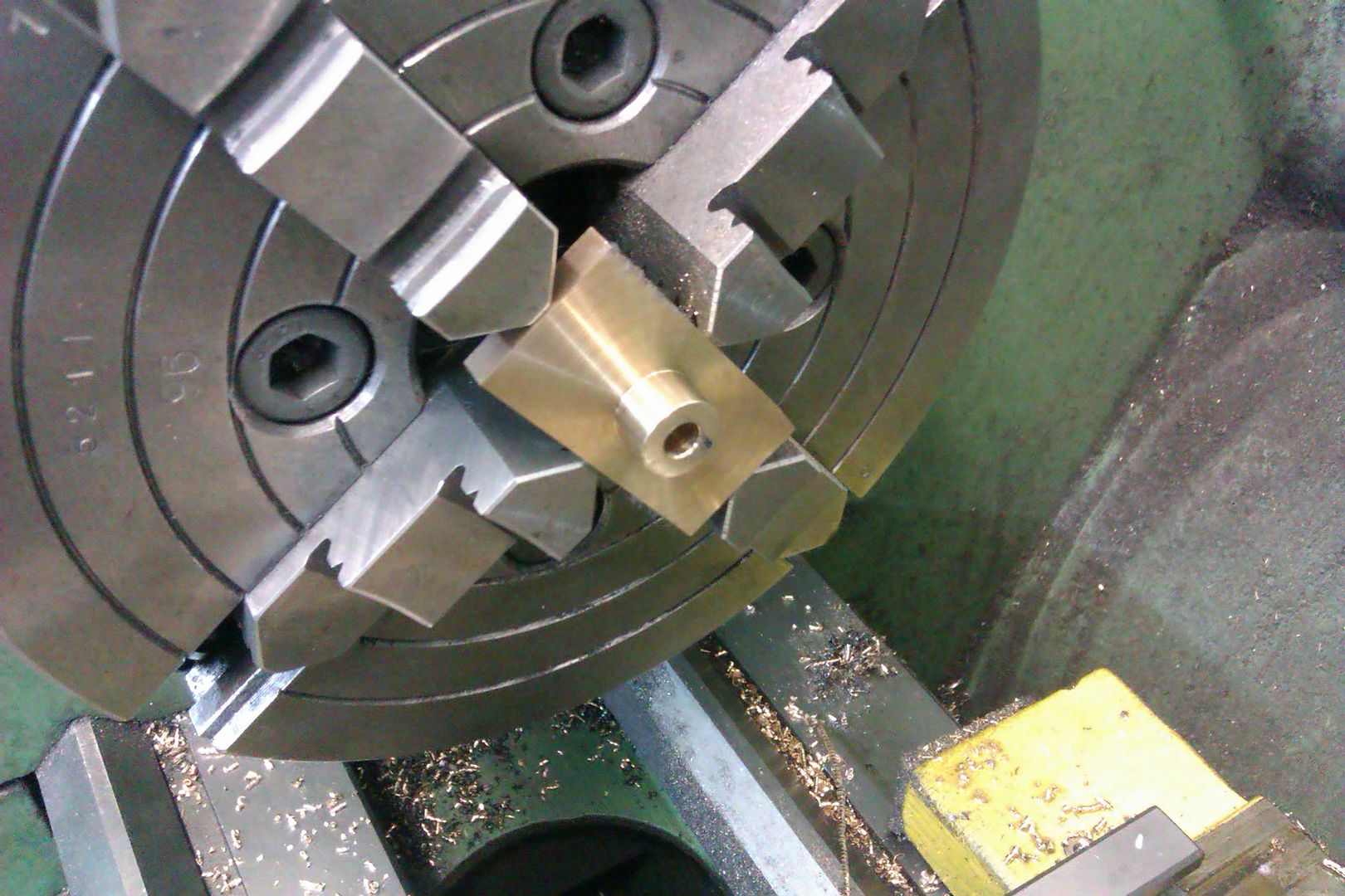
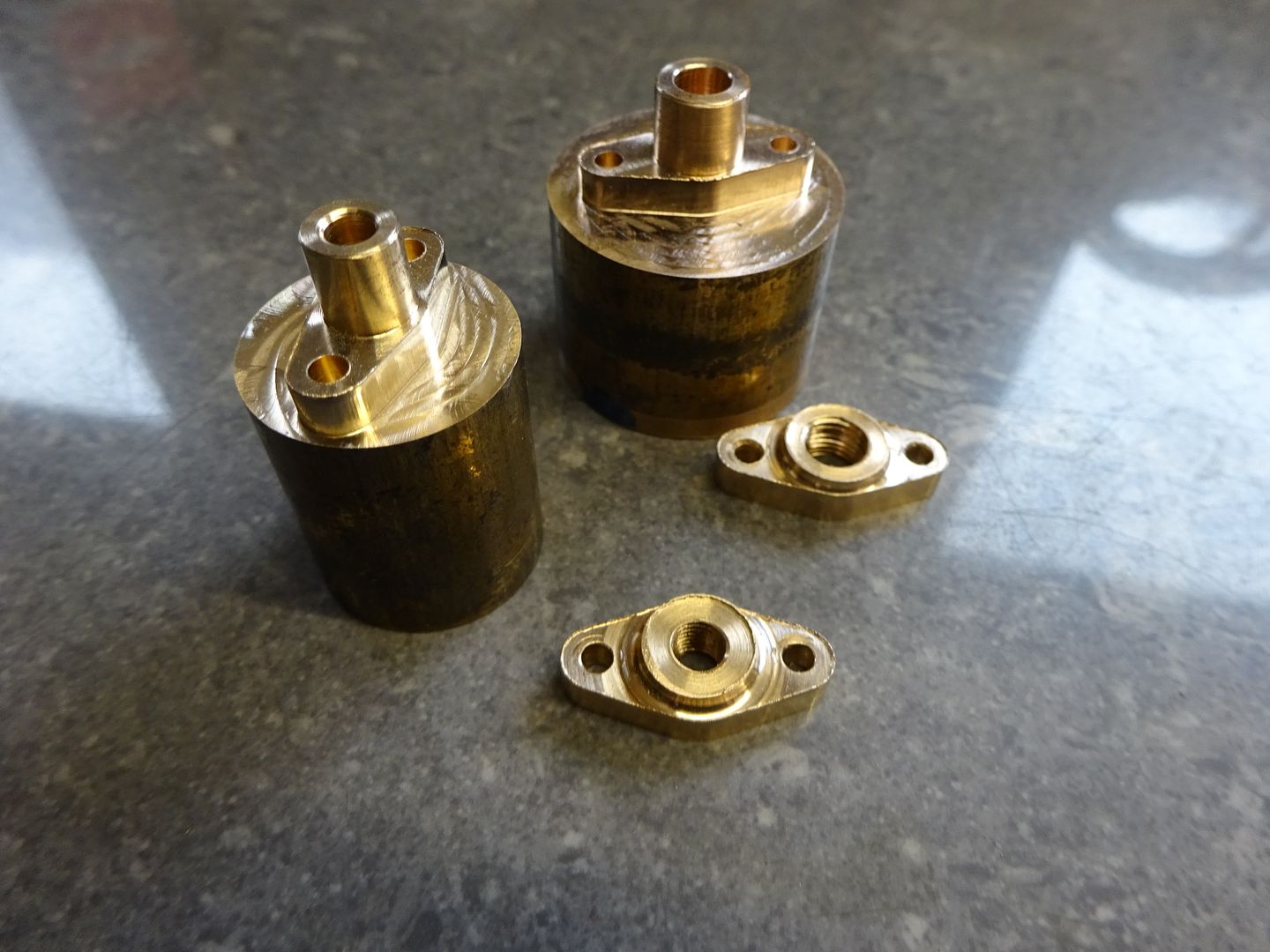
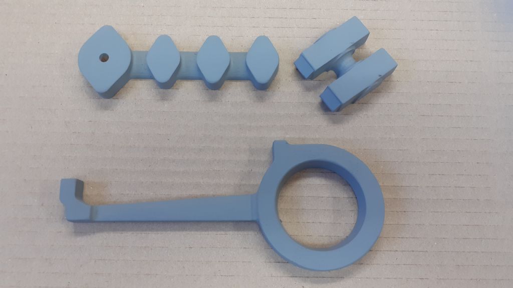
In the thread by Dr G on his making of the Stuart Twin Victoria the making of these small but significant parts has been discussed. Rather than spoil Doc's thread here are a few images to explain an alternative way of manufacture.
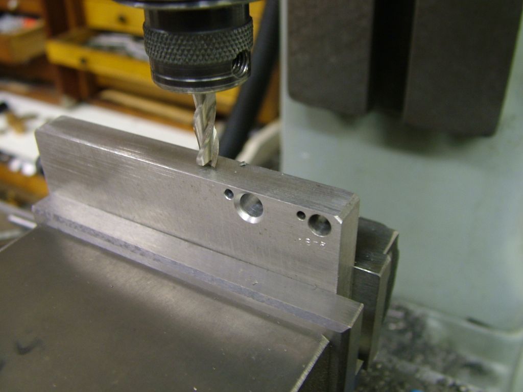
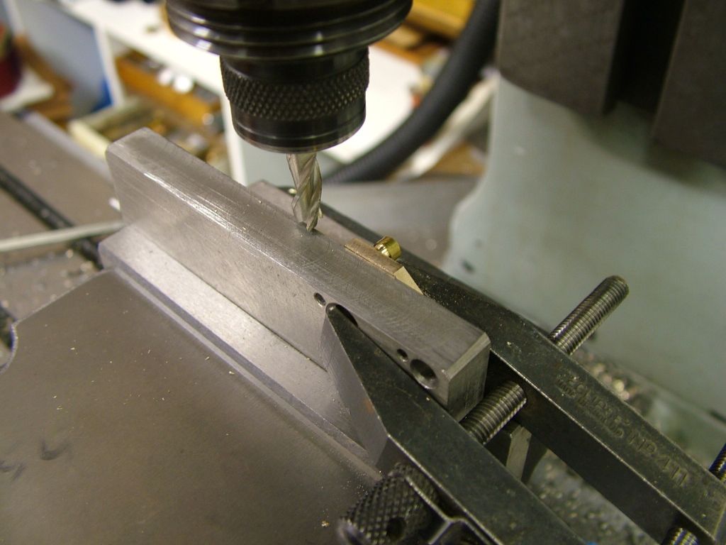
First off some simple maths to establish the half angle of the diamond is required. Once this is known the 'fixture' can be tackled. It's just a simple piece of mild steel plate (ali would do) with two parallel edges a bit wider that the mill vise depth.This has a hole drilled in close to the edge that will take the diameter of the gland boss. Another hole is drilled to coincide with the gland bolt hole at the angle previously worked out
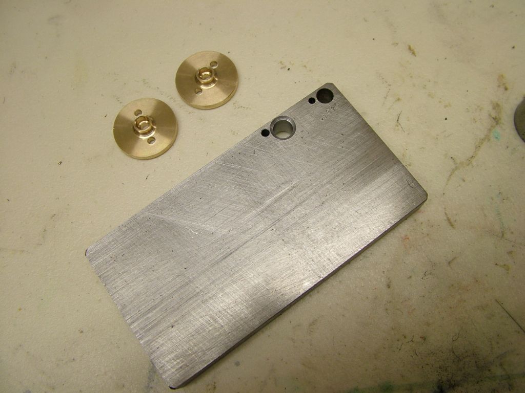
The plate with two embryo glands. The deep chamfer is to cater for the radius on the boss

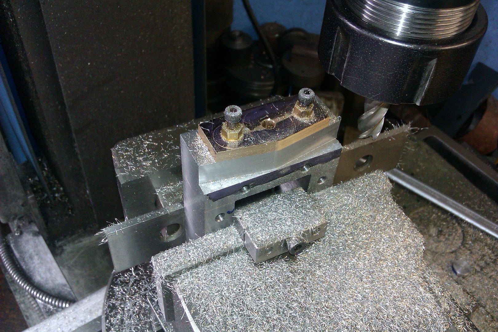
The plate is set level in the vise (image gives the appearance of an angle but it is parallel with the table) and the cutter set to the depth required.

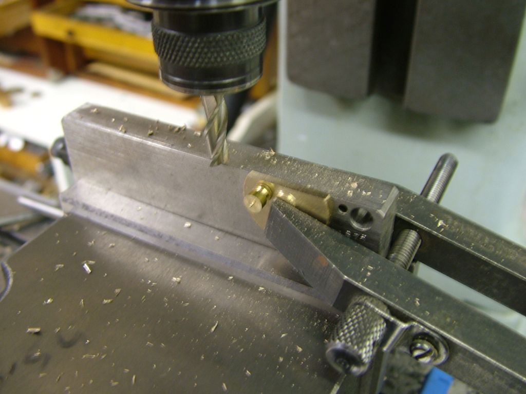
A small pin is turned to match the clearance hole and the boss clamped in place. The part is milled to the depth set……..

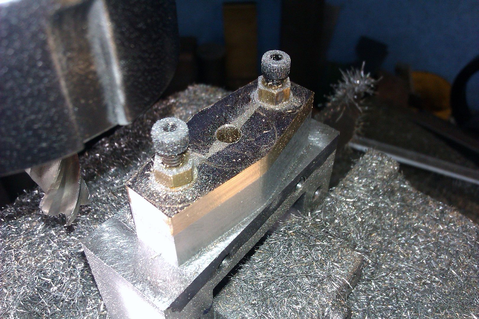
………then rotated to mill the opposite side

The plate can then be reversed or the part inserted from the other side of the plate to do the same on the remaining edges

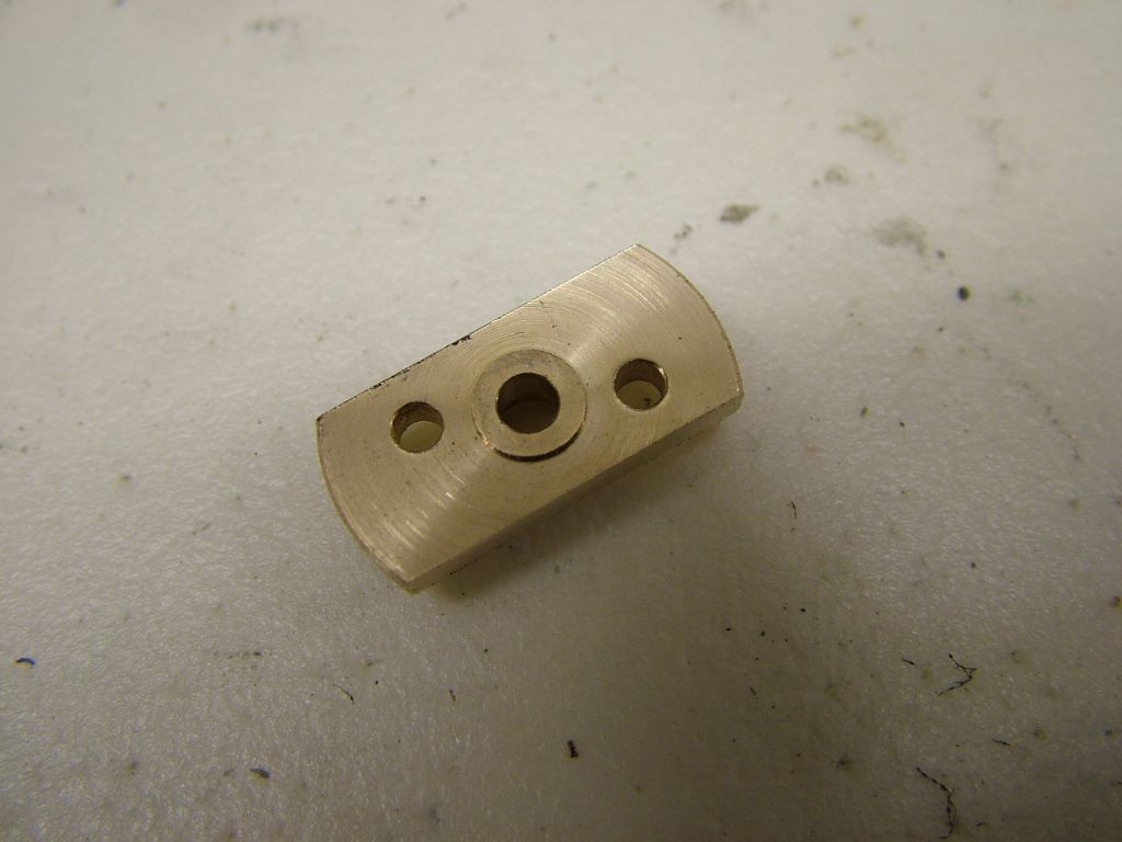
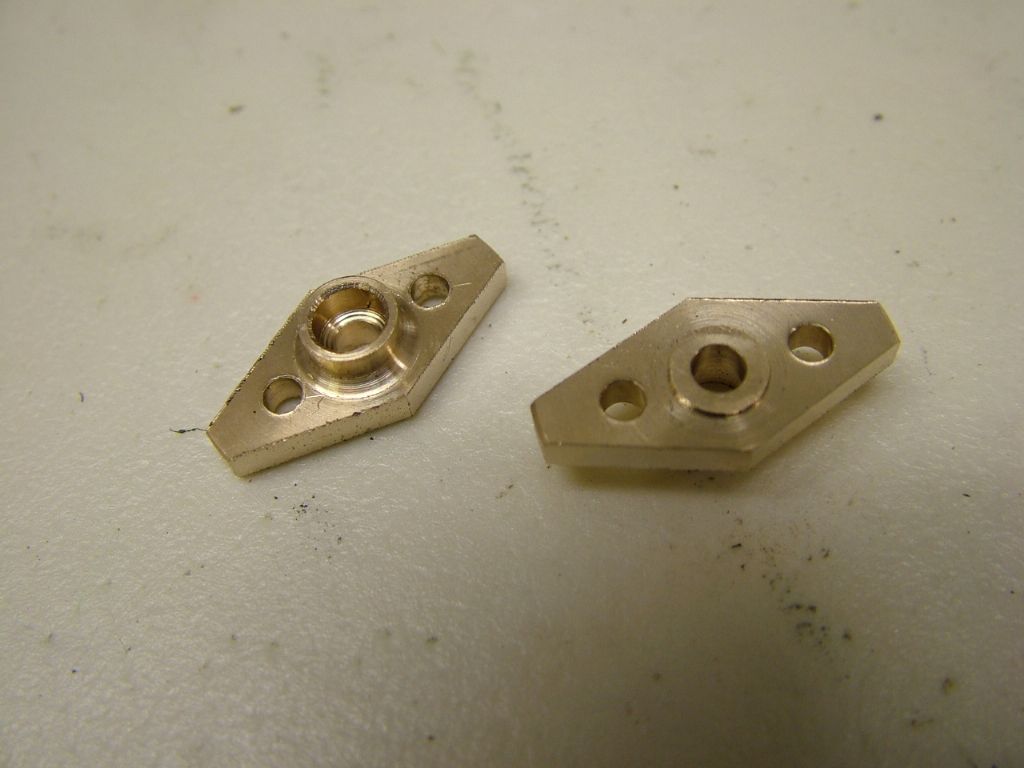
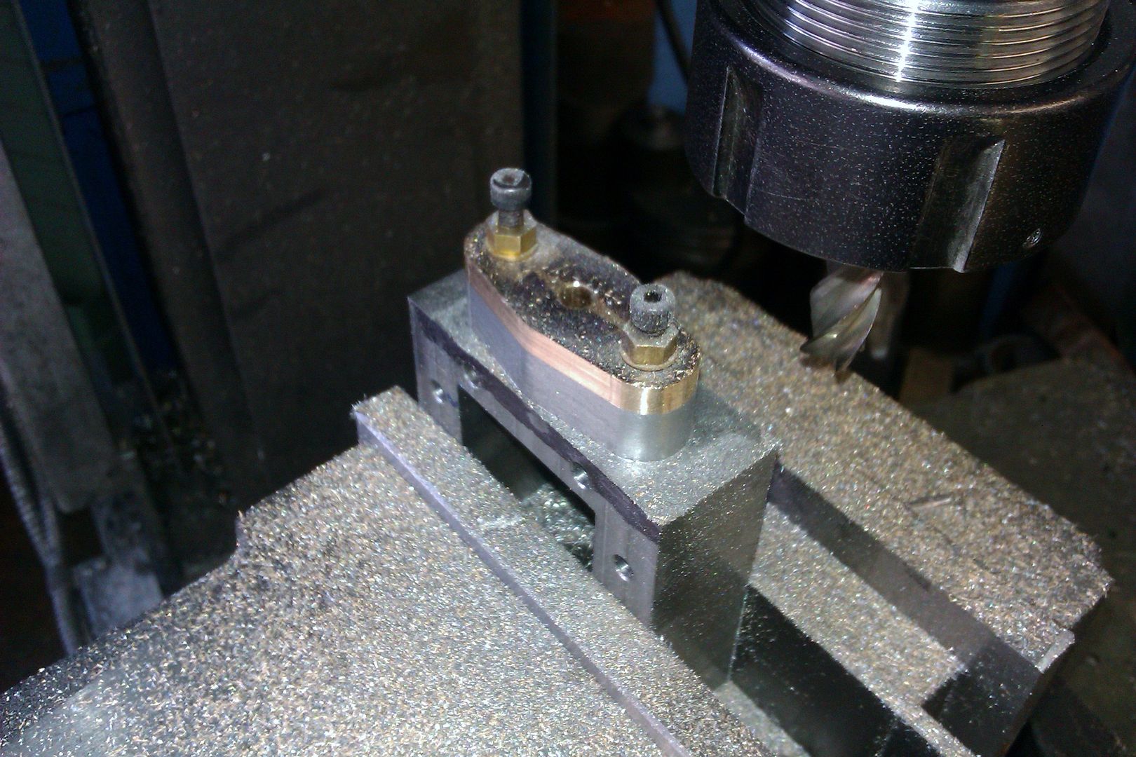
Initial milling complete

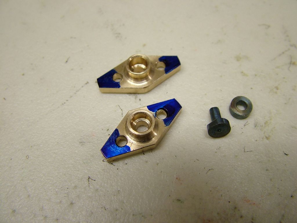
A filling button is turned up and hardened…..

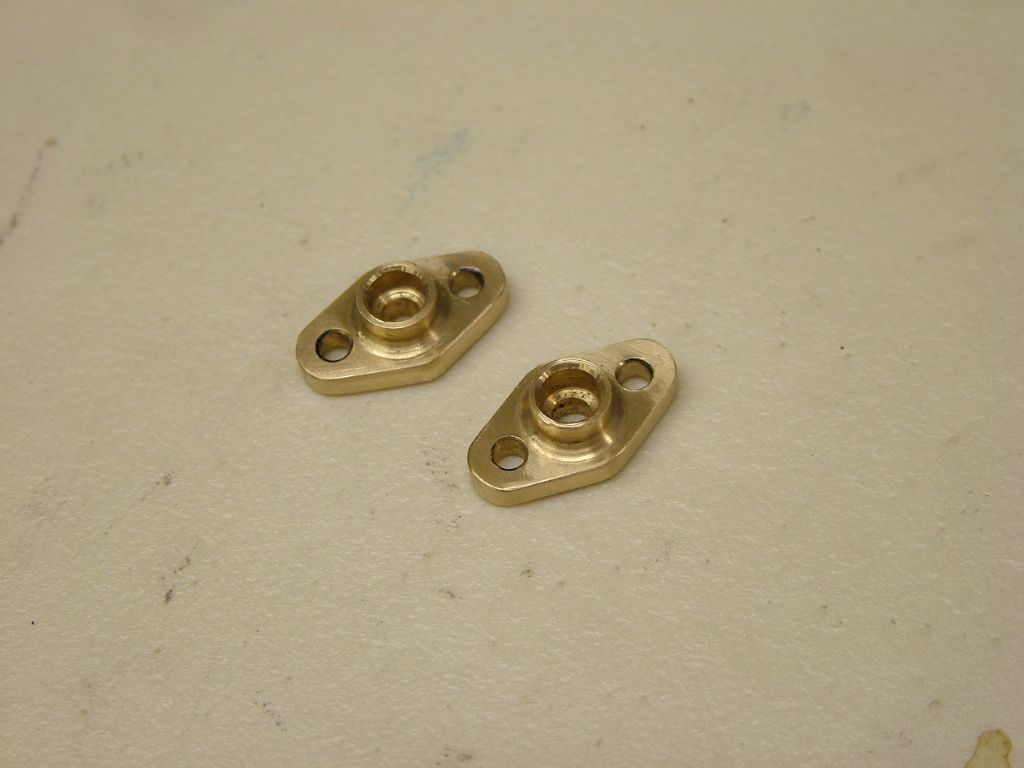
…….and the ends brought to shape by filing


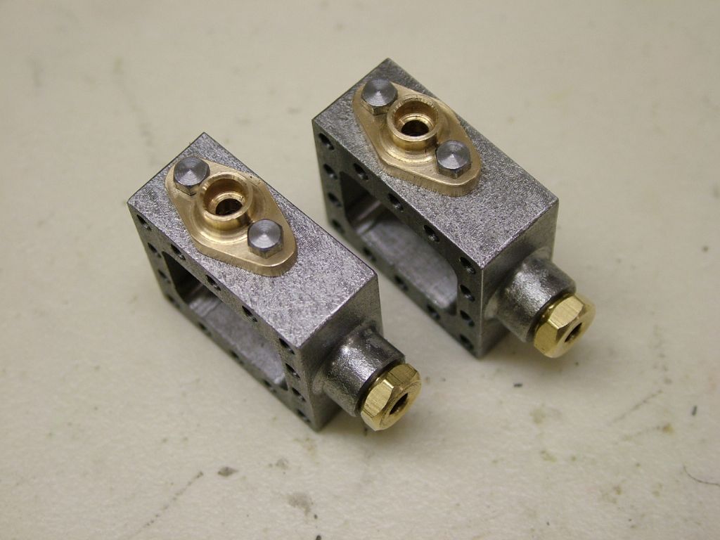
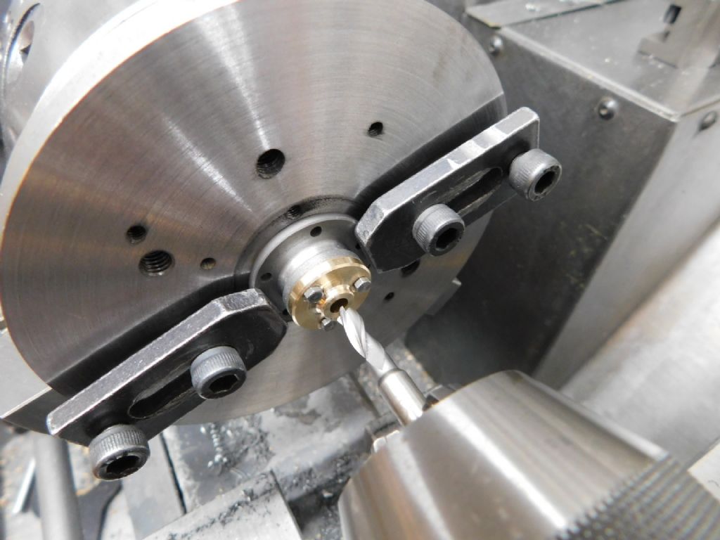
I appreciate this shows steam pipe glands but the principle is exactly the same for piston rod glands. The part would not have a centre hole in at this stage however. It would then be bolted to it's respective cylinder cover and be drilled and reamed together
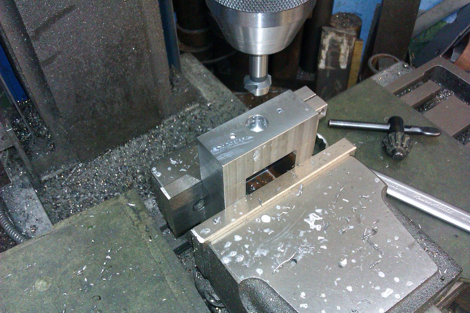
This image shows a round gland being opened up with an FC3 cutter before being drilled and reamed in such an operation

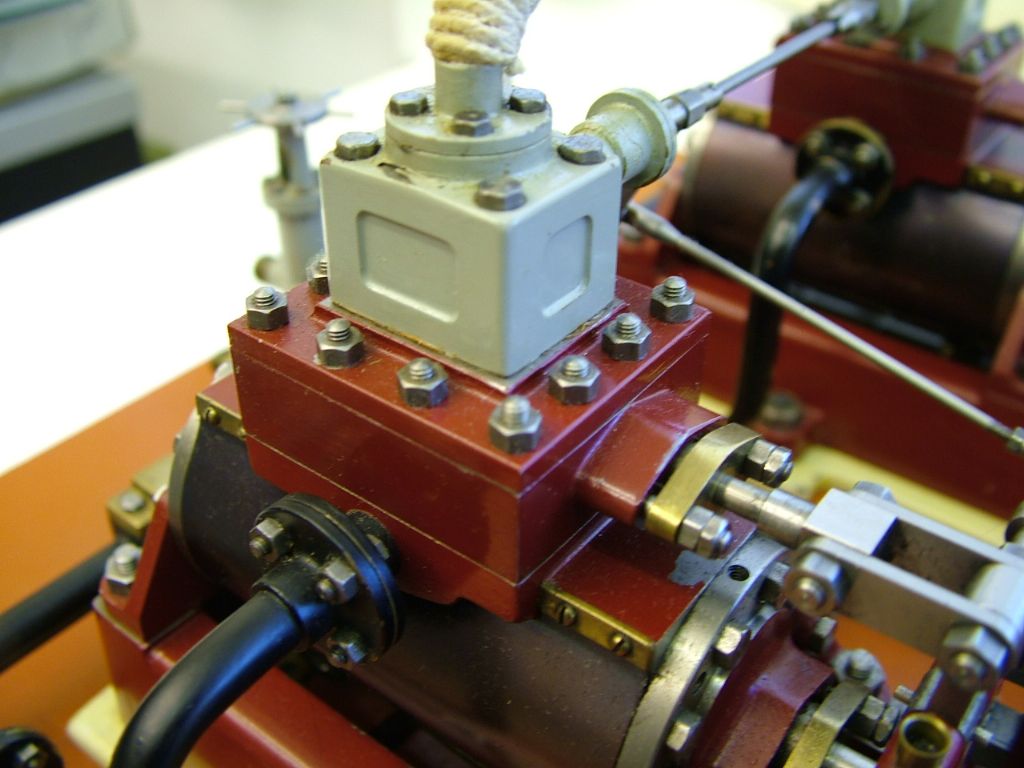
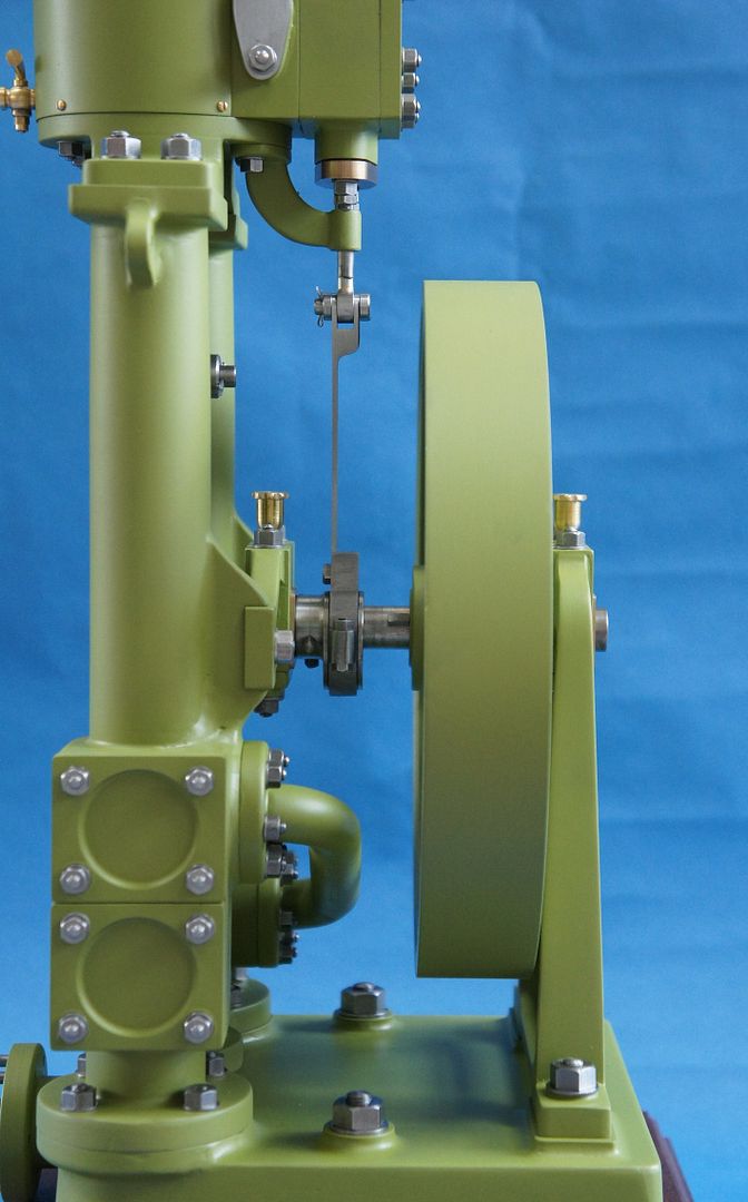
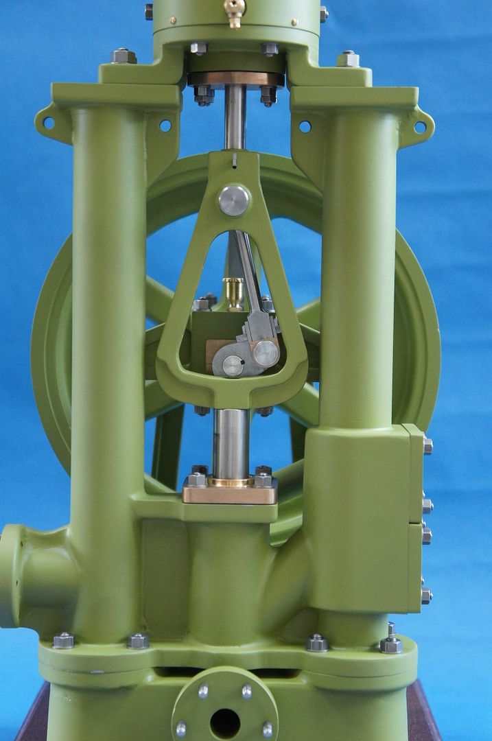
Here is a pic of my Twin Vic which is when I came up with the above method – have used it many times since

Hope that's of interest to you and to anyone else that it can benefit
Ramon (Tug)
 Ramon Wilson.

