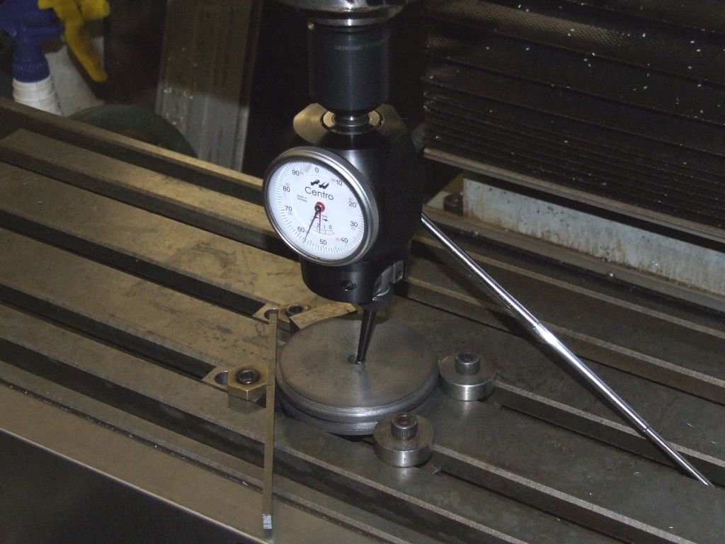
Diacator made by Dietest

Advert

Diacator made by Dietest

Home Forums Beginners questions Diacator made by Dietest

Viewing 22 posts - 1 through 22 (of 22 total)
  • Author
    Posts
  • #657153
    Chris Mate
    Participant
      @chrismate31303

      Hi,

      Does anybody here owns or used a Diacator made by Dietest for centering a hole below your mill spindle, similar function to the coaxial centering indicators-?

      Advert
      #11558
      Chris Mate
      Participant
        @chrismate31303

        For centering your mill

        #657165
        bernard towers
        Participant
          @bernardtowers37738

          Surely it’s a coaxial indicator by another name?

          #657176
          DiogenesII
          Participant
            @diogenesii

            Looks like a good instrument – how much is it?

            If I had a choice between buying a co-ax indicator or a DRO, I'd buy a DRO.

            If you have a DRO you probably don't need a co-ax indicator.

            #657178
            Michael Gilligan
            Participant
              @michaelgilligan61133

              I don’t … but Niels does [or did] :

              .

              .
              MichaelG.
              #657186
              Nigel Graham 2
              Participant
                @nigelgraham2

                Diogenes…

                I must be missing something here how do you use a DRO to set a work-piece to the centre of an existing hole without something between it and the rim of the hole?

                You still need some type of edge-indicator, whether you use a DRO or the handwheel dials.

                #657192
                Robert Atkinson 2
                Participant
                  @robertatkinson2

                  The lever below the DTI translates sideways movement of the probe into vertical and pointer deflection.
                  The clever bit is allowing the dial to remain stationary.

                  Robert

                  #657193
                  Robert Atkinson 2
                  Participant
                    @robertatkinson2

                    Looks like I was right. Google is your friend:

                    Diacator

                    Robert.

                    Edited By Robert Atkinson 2 on 20/08/2023 09:27:18

                    #657195
                    Clive Foster
                    Participant
                      @clivefoster55965

                      Nigel

                      Simple way uses the DRO zero and half functions with a solid rod in teh chuck as an indicator.

                      Set up as best you can by eye.

                      Choose an axis.

                      Move until the rod just touches one side of the bore being centred.

                      Zero the axis.

                      Move until the other side just touches the rod.

                      Hit the hard setting button.

                      Move to zero which should be in the middle of that axis.

                      Repeat touch off process and zeroing on other axis.

                      Zero – zero should now be in the middle to within the error of your touch off process.

                      Repeat process to verify before starting work.

                      As touch off errors are opposite they tend to cancel out assuming your process is reliable. Generally feeling for drag as you rotate the spindle is good enough.

                      An advantage of co-axial indicators is that they will show up non circular bores. The DRO method only finds the centre relative to the testing lines.

                      Clive

                      #657196
                      DC31k
                      Participant
                        @dc31k

                        A potential advantage of the co-ax indicator types used in a hole compared to a standard edge finder is that they will work at zero rpm. You can turn the spindle gently using one hand and see how the needle moves (even rotating it in discrete 90 degree increments if necessary). With an edge finder, it needs some powered rpm to see the wobble disappear and then observe the 'kick'.

                        With a co-ax indicator, finding centre is quite a smooth single operation. Poke in the hole and adjust until the needle does not move and zero everything. With an edge finder, there are four (maybe six) distinct actions that have to be coordinated with DRO button pressing.

                        Where a co-ax indicator might score is adjusting the height of a dividing head tailstock especially if you are setting it up to cut a taper.

                        Could we come up with something a co-ax can do that a standard indicator and a mirror cannot do?

                        #657198
                        bernard towers
                        Participant
                          @bernardtowers37738

                          One of the big problems with a lot of commercial coax indicators is the amount of headroom required so if you have a small mill they can be impossible to use which is why I when the route of making my own. A nice satisfying project which gets used again and again.6dbf7fcb-cf00-40ff-a368-f4334e879ac6.jpeg

                          #657202
                          Brian G
                          Participant
                            @briang

                            I assume there must be something special to justify a price three times that of a Blake indicator and nearly twenty times that of generic ones? As it is used in the same way I cannot see it speeding up the operation enough to save much cost.

                            **LINK**

                            Brian G

                            #657207
                            Michael Gilligan
                            Participant
                              @michaelgilligan61133
                              Posted by Brian G on 20/08/2023 09:51:41:

                              I assume there must be something special to justify a price three times that of a Blake indicator […]

                              .

                              Presumably a combination of ‘country of origin’ and claimed accuracy

                              ’though I note that the certificate is unsigned !

                              MichaelG.

                              .

                              4-46.jpeg

                              #657214
                              Anonymous
                                Posted by Michael Gilligan on 20/08/2023 10:24:19:

                                Presumably a combination of ‘country of origin’ and claimed accuracy

                                ’though I note that the certificate is unsigned !

                                4-46.jpeg

                                I have a Haimer Centro:

                                centro_using.jpg

                                Claimed accuracy is 2 microns not that I have any way of confirming that. The only problem is that (as Bernard says) it does need a fair amount of headroom.

                                Andrew

                                #657231
                                Chris Mate
                                Participant
                                  @chrismate31303

                                  I am looking at the different types to get a better picture of all.

                                  The other day I made a test cut with new boring head, I actually used the boring head/bar-Insert itself to centre the head above at 1st,… and then in the hole by listining to the boring bar tip as it go around, mill switched off, turn and adjust by hand, you don't want to break a bar or the head turning it on. It worked out after some effort.

                                  These tools may not work out always:
                                  I then realised there might be a situation, and thats a situation I might have to deal with if my current quick plan proves not to work out for restoring the RF 115 Rong Fu bandsaw which was dropping blades when I received it, a situation where indicating with a tool like this means not much if the bore has been weared out uneven.

                                  So in a case like this, where you want a shaft to line up correctly from your boring and sleeving excersize, you must find a ring visible outside of the wear pattern(Hole) to indicate the original alignment and to the centre of your spindle. So in this case I will probably using the boring head and bar insert tip to get the job done right, time consuming but hopefully lined up correctly.

                                  Note:It seems these tools has a very interesting point in design apart from what was mentioned above, and that is its accuracy of indication depends on two surfaces, maybe 3 in the design, otherwise its not effected.
                                  That brings me to a point after some thought, one could use this tool straight in the boring head and let it swing from there, use that adjustment initially to set it up, then let it swing slowly and it will move but still faces you and get the job done uneffected, I never saw anybody uses it like this-?

                                  Make a tool:
                                  I can attemp to make such a tool shorter(More headroom) but then the indicator will sit sideways and not in path and upright, and it will not be accurate, but will only indicates movement of not being on centre, so you cannot off centre someting to an exact figure if you want to.

                                  Wiggler:
                                  I also thought of using the wiggler stiff tightened to indicate a circle, but not in the way a wiggler is normally used.

                                  Lazer lights:

                                  I also saw use of small lazer lights that just clip over spindle and shine a circle which you then position.
                                  This seem interesting and easy.

                                  What do you think-?.
                                   

                                  Edited By Chris Mate on 20/08/2023 16:50:08

                                  #657235
                                  DC31k
                                  Participant
                                    @dc31k
                                    Posted by Chris Mate on 20/08/2023 16:34:39:

                                    That brings me to a point after some thought, one could use this tool straight in the boring head and let it swing from there

                                    I might be misunderstanding you here, but I do not think that would work.

                                    The typical 50mm boring head has two vertical holes in it for the tools. One of those holes would have to be set (adjusted) concentric with the boring head's axis of rotation in order for it to be used to house a co-axial indicator (or even a standard edge finder).

                                    You could use a standard lever DTI in the manner you describe but not something where the dial always faces you and the mechanism rotates.

                                    When you use the point of the tool to find centre as you describe above, it is always a constant distance from the rotation axis.

                                    #657237
                                    Michael Gilligan
                                    Participant
                                      @michaelgilligan61133
                                      Posted by Chris Mate on 20/08/2023 16:34:39:
                                      .

                                      […]

                                      I also saw use of small lazer lights that just clip over spindle and shine a circle which you then position.
                                      This seem interesting and easy.

                                      What do you think-?.

                                      .

                                      There was a long and interesting discussion about laser centring devices on here a few years back.

                                      … if you can’t find it, I will have a look later.

                                      MichaelG.

                                      #657249
                                      Chris Mate
                                      Participant
                                        @chrismate31303

                                        Hi Michael,


                                        A)The Lazer device is called "CentreQuick" centering …..

                                        B)About your question regarding the ordinary coaxel centering devices operation.

                                        -Normally they fitted to spindle/collet and spin internally as the spindle runs, mill motor running.
                                        In this case you use it automatic way, it turns many revolotions around the spindles arc which you then compare to the hole you want to align the X/Y axis.

                                        -My suggestion is if you fit this same tool to the Boring head itself, the mill motor stay switch off, you use it manually, meaning you turn spindle with hand and you confirm within one revolution for each revolution as now it follows whatever acr the boring head delivers to it as spindle is slowly turned by hand. The tool will move but not turn within an arc as it would if you switch the mill motor on, there is a difference. Maybe I am a bit stupid thinking here, but I will keep on thinking more about it. I can see the difference, you don't want an arc running within an arc so to speak. I am not an engineer, just wild thoughts for now, it may or may not be practical.

                                        Edited By Chris Mate on 20/08/2023 19:18:40

                                        #657252
                                        peak4
                                        Participant
                                          @peak4

                                          I was going to post a link to the excellent Dan Gelbart video, but came across this which has the video embeded.
                                          The relevant part is from about 2 min 20 on
                                          https://www.printables.com/model/58546-dan-gelbart-laser-center

                                          I don't have a 3D printer, but it might be of interest to those who do play with them.

                                          Bill

                                          #657253
                                          Michael Gilligan
                                          Participant
                                            @michaelgilligan61133
                                            Posted by Chris Mate on 20/08/2023 19:17:37:

                                            Hi Michael,

                                            […]

                                            B)About your question regarding the ordinary coaxel centering devices operation.

                                            […]

                                            .

                                            That’s strange … I don’t recall asking a question

                                            MichaelG.

                                            #657274
                                            John McNamara
                                            Participant
                                              @johnmcnamara74883

                                              Re the image on the link in peak4's post
                                              https://www.printables.com/model/58546-dan-gelbart-laser-center

                                              I like the spherical arrangement of the laser mount adjustments.
                                              adjustment in two planes with two lock screws only.
                                              That is a nice piece of design and part minimisation.

                                              Not easy to machine but easy to 3D Print.

                                              #657275
                                              Michael Gilligan
                                              Participant
                                                @michaelgilligan61133
                                                Posted by Chris Mate on 20/08/2023 19:17:37:

                                                Hi Michael,

                                                A)The Lazer device is called "CentreQuick" centering …..

                                                […]

                                                .

                                                That took a bit of finding: **LINK**

                                                https://www.centerquic.com

                                                … but it basically looks like an interpretation of Dan Gelbart’s idea

                                                MichaelG.

                                              Viewing 22 posts - 1 through 22 (of 22 total)
                                              • Please log in to reply to this topic. Registering is free and easy using the links on the menu at the top of this page.

                                              Advert

                                              Latest Replies

                                              Home Forums Beginners questions Topics

                                              Viewing 25 topics - 1 through 25 (of 25 total)
                                              Viewing 25 topics - 1 through 25 (of 25 total)

                                              View full reply list.

                                              Advert

                                              Newsletter Sign-up