Designing bevel gears 3:1 ratio

Advert

Designing bevel gears 3:1 ratio

Home Forums General Questions Designing bevel gears 3:1 ratio

Viewing 12 posts - 1 through 12 (of 12 total)
  • Author
    Posts
  • #159914
    Emgee
    Participant
      @emgee

      Hi

      Bevel gear box with approx 3:1 input to output ratio, gear axis at 90 deg.

      Read Ivan's book and other related info but still unable to calculate dimensions and angles required. Any and all help appreciated to design/dimension parts.

      Max OD to be 40mm

      Gear DP as large as possible within size/ratio restriction.

      Emgee

      Advert
      #23450
      Emgee
      Participant
        @emgee
        #159918
        Neil Wyatt
        Moderator
          @neilwyatt

          Hello Emgee,

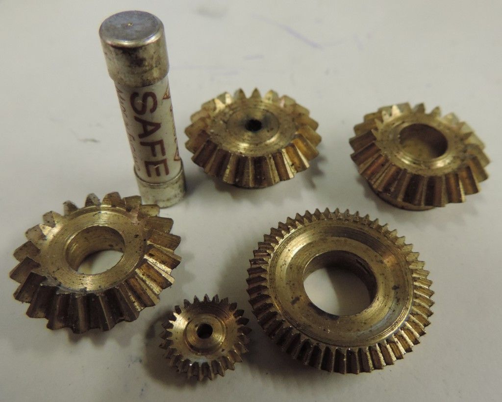
          It can be done. All the gears including the pair at the front of the picture below were designed and made using Ivan's method.

          The starting point are two cones whose points meet and whose circular bases are the starting point for designing the gears. Assume the teeth take up 1/4 of the face of the cone.

          If your big gear is 40mm at the outside, the inner part will be 30mm diameter. The smaller gear will be 13.3mm OD, and 10mm at the inner end.

          Calculations of the gear size all base on the small end so say we have 30mm with 60 teeth and 10mm with 20 teeth you are looking at 0.5MOD, which is pretty small.

          You can use fewer teeth, but…

          What will the gearbox be used for?

          Neil

          bevel gears.jpg

          #159921
          Bob Brown 1
          Participant
            @bobbrown1

            Commercial gears seem to be 15/45 teeth, matched pair, module 0.8 with an OD of 36.6mm for the larger gear.

            Edited By Bob Brown 1 on 06/08/2014 18:38:20

            #159927
            Neil Wyatt
            Moderator
              @neilwyatt

              Commercial gears may not be the 'constant depth bevel' type described by Ivan Law. Their module will be that of the large end of the cone. The constant bevel type need a standard cutter to be able to pass through the gap at the small end of the teeth, hence the modest, but noticeable, discrepancy.

              Neil

              #159947
              Emgee
              Participant
                @emgee

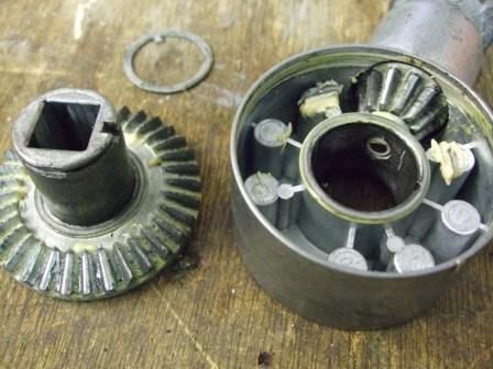
                Thanks Neil and Bob for info, I now have more info on the gear having stripped the box down, pictures in my album.

                Bevel gear 2.75:1 output:input. Pinion No of teeth =12

                Large gear Diameter 57.80mm, No of teeth=33 1.5 MOD at centre of 9.5mm wide gear tooth.

                Tooth Angle is approx 17 degrees (107 deg from vertical axis)

                This box is from a wind out awning that skips teeth when winding in. Bought a new box but there is so much free play in the spindle, and 30 degrees of backlash between gear teeth, I'm concerned it will need replacing again very soon if I fit it.

                Any more help very much welcome.

                Rgds, Emgeebox dismantled.jpg

                #432881
                Chris Taylor 3
                Participant
                  @christaylor3

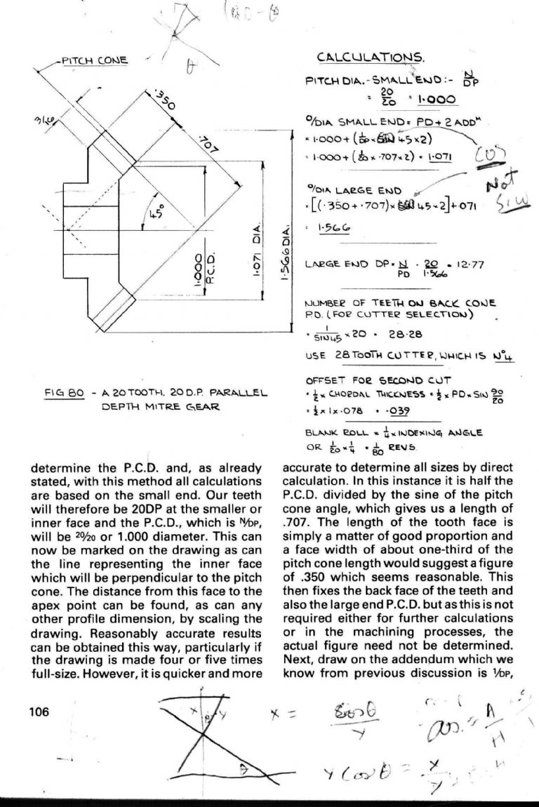
                  I am also looking at machining some bevels using Ivan Law’s parallel depth method, but 38DP Meccano size. I’m having difficulty following the fig.80 calculation, partly because Ivan chose 20 tooth and 20 DP so when 20 appears in the calculation I’m not sure which parameter is referred to. Two questions for the experts: number of teeth on back cone PD =1/sin45 x 20, presumably the 20 is number of teeth at the small end? And where does this come from. Second question: the offset for the second cut also has a 20, which is clearly small end N, but where does this come from. Any help much appreciated

                  #432944
                  Howard Lewis
                  Participant
                    @howardlewis46836

                    If anyone wants a new, and unused, commercial right angle box with a 3:1 ratio, (Flanges are 70 mm and 90 mm diameter ).

                    PM me to arrange collection from Peterborough, UK. A donation to PSME funds might be welcomed.

                    Howard

                    #432982
                    John P
                    Participant
                      @johnp77052

                      Posted by Chris Taylor 11/10/2019 20:24:09

                      I am also looking at machining some bevels using Ivan Law’s
                      parallel depth method, but 38DP Meccano size. I’m having
                      difficulty following the fig.80 calculation, partly because Ivan
                      chose 20 tooth and 20 DP so when 20 appears in the calculation
                      I’m not sure which parameter is referred to. Two questions
                      for the experts: number of teeth on back cone PD =1/sin45 x 20,
                      presumably the 20 is number of teeth at the small end? And
                      where does this come from.
                      Second question: the offset for the second
                      cut also has a 20, which is clearly
                      small end N, but where does this come from.
                      Any help much appreciated

                      Hi Chris

                      The 20 that you refer to is the number of teeth in the gear.
                      and is the same pitch diameter PD as a normal spur gear.
                      It is unfortunate that the example shown in the book is shown as
                      a mitre gear as this seems to have caused much confusion over time.
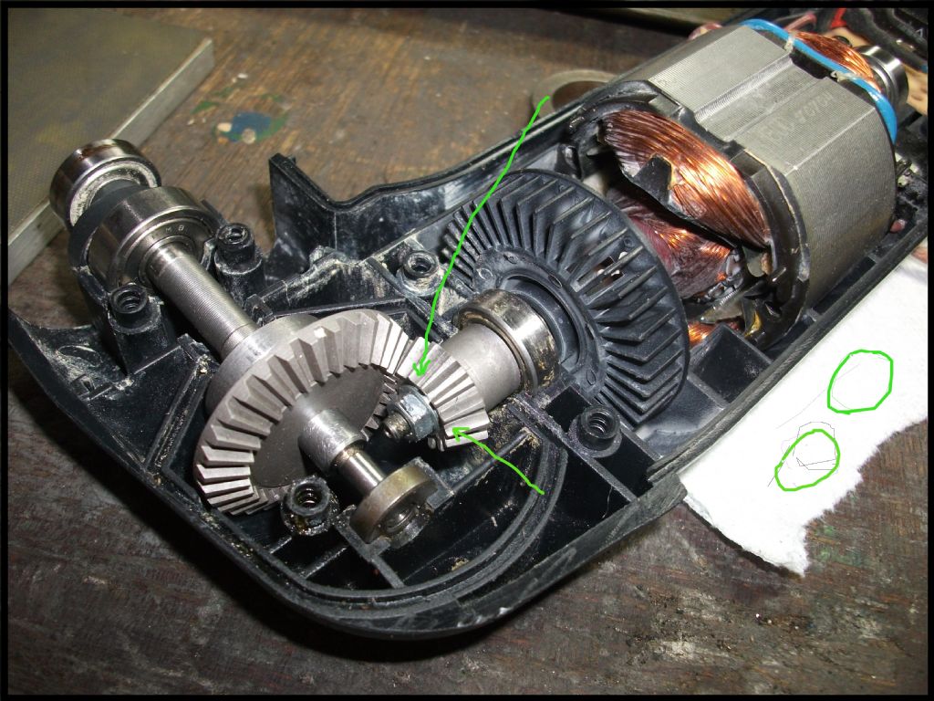
                      The drawing shown here is of a 15 tooth parallel depth gear 30 dp ,
                      because the angle formed from the back cone it equals a spur gear
                      of 16.62 teeth 2 x .277 inch .554 inch x 30 dp ,this falls
                      just below the range of a No 6 cutter 17 to 20 teeth but is just
                      usable as a gear. The second photo shows this made gear
                      and you may be able to see the slight undercut at the root ,arrowed.
                      The second question the 20 again is the tooth number, see page
                      109 fig 84.

                      John

                      15 tooth .jpgdetail sander1.jpg

                      #432984
                      Neil Wyatt
                      Moderator
                        @neilwyatt
                        Posted by Chris Taylor 3 on 11/10/2019 20:24:09:

                        I am also looking at machining some bevels using Ivan Law’s parallel depth method, but 38DP Meccano size. I’m having difficulty following the fig.80 calculation, partly because Ivan chose 20 tooth and 20 DP so when 20 appears in the calculation I’m not sure which parameter is referred to. Two questions for the experts: number of teeth on back cone PD =1/sin45 x 20, presumably the 20 is number of teeth at the small end? And where does this come from. Second question: the offset for the second cut also has a 20, which is clearly small end N, but where does this come from. Any help much appreciated

                        Check out this thread before your start!

                        http://www.model-engineer.co.uk/forums/sendtofriend.asp?th=140757&p=2428972

                        #433013
                        Chris Taylor 3
                        Participant
                          @christaylor3

                          Thanks John for the example and thanks Neil for the corrected calculation, the fig 80 calculation is a double whammy, using 20 for both N and DP and then a 45° bevel, because of course sine 45 is the same as cosine 45 so you still get the correct answer! I need to go back to first principles and fully understand the geometry before making any swarf.

                          #433032
                          Michael Gilligan
                          Participant
                            @michaelgilligan61133
                            Posted by Chris Taylor 3 on 12/10/2019 23:31:36:

                            Thanks John for the example and thanks Neil for the corrected calculation, the fig 80 calculation is a double whammy, using 20 for both N and DP and then a 45° bevel, because of course sine 45 is the same as cosine 45 so you still get the correct answer! I need to go back to first principles and fully understand the geometry before making any swarf.

                            .

                            Very well said, Chris yes

                            “go back to first principles and fully understand the geometry before making any swarf.”

                            … ‘though, as you will see from another current thread, that may not be the populist view. sad

                            MichaelG.

                          Viewing 12 posts - 1 through 12 (of 12 total)
                          • Please log in to reply to this topic. Registering is free and easy using the links on the menu at the top of this page.

                          Advert

                          Latest Replies

                          Home Forums General Questions Topics

                          Viewing 25 topics - 1 through 25 (of 25 total)
                          Viewing 25 topics - 1 through 25 (of 25 total)

                          View full reply list.

                          Advert

                          Newsletter Sign-up