I have made 'some' progress on the arms and pivots for this 'printer'…
I will create a new post next time round to try decontaminate the rest of the 'progress'..
I made all the arms, arm sockets, and the various pivots – the main drive pivot, the two elbow pivots, and the tool holder pivot. The main drive pivot uses 4 preloaded ball bearings, and the elbow and tool pivots use 30mm OD and 35mm OD thrust bearing respectively.
All are preloaded to ensure the assembly is stiff to prevent any tool head sag, co-planarity of motion is also important for obvious reasons.
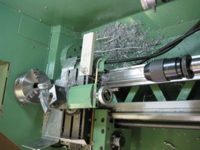
And LOTS of swarf was made..
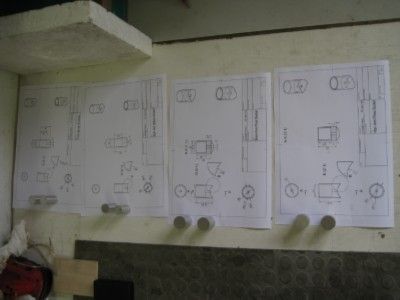
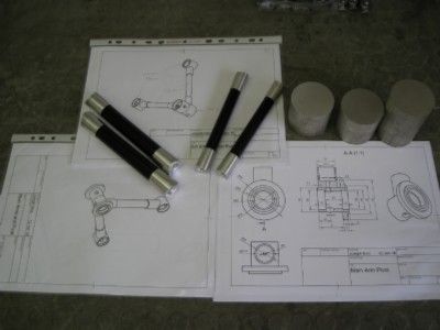
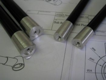
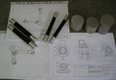
The arms and sockets – not yet loctited..and Raw stock for pivots, and drawings from Fusion 360.

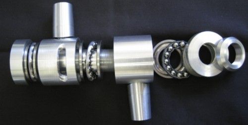
The Tool Pivot, exploded view..Has a central 18mm hole through which the extruder head passes the filament.
The idea is to have the hot end below the pivot, and the nozzle/hot end be inductively heated – working of a prototype of that concept and has great promise..

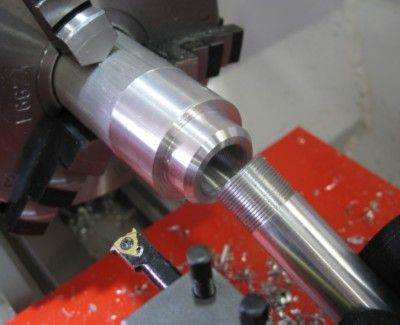
The central tube in the Tool Pivot – threaded using my ELS on the 14D with multifix retracting tool holders..

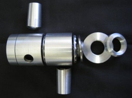
Part exploded view of one of the two Elbow Pivots. The short tubes, as above, are the sockets into which the tubing arms fit. These socket will be TIG welded onto the pivots and the tube arms inserted , in a jig to ensure length and co-planarity are met, and loctite applied

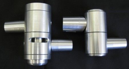
Tool and Elbow Pivots part assembled, not yet welded..

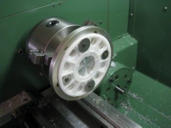
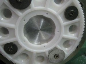
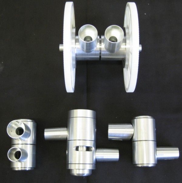
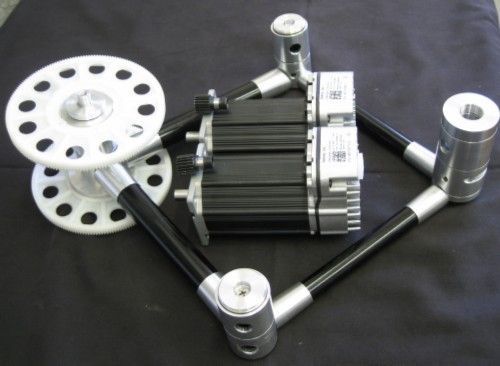
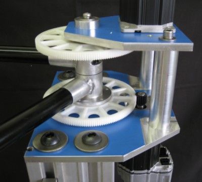
The drive Pivot is uppermost in the image below – fitted with the main reduction drive gears – 140mm diameter gears, from an Align 700 RC helicopter main rotor drive.
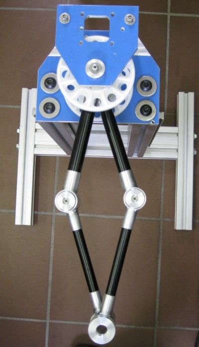
The Left and Right Elbow Pivots are seen, with the Tool Pivot between.

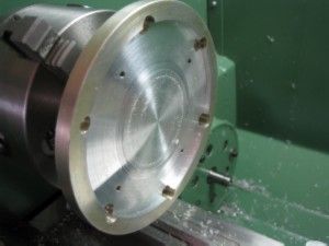
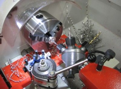
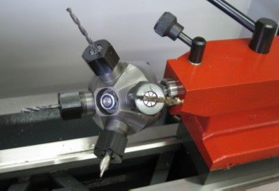
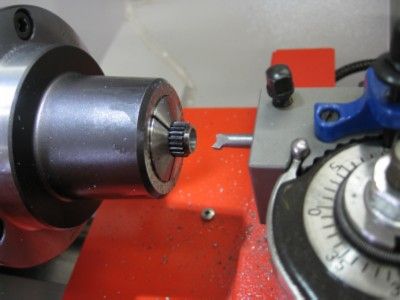
First time I used the new lathe's Tailstock Turret – had a handful of threaded bosses to make, and it came in very handy!

It uses ESX16 collets…

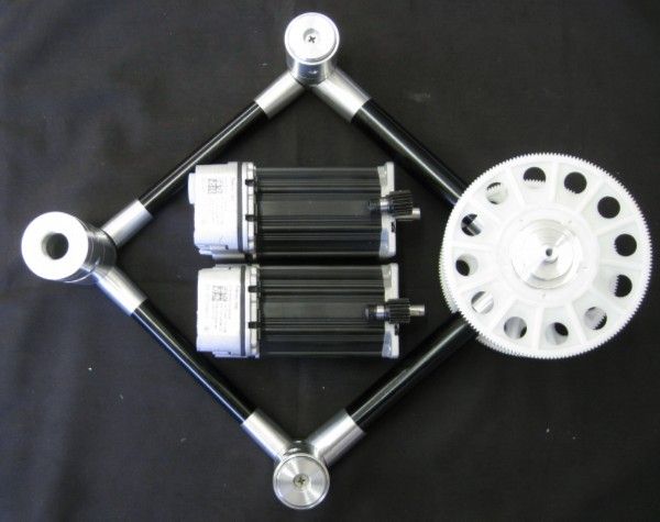
Mockup of assembly with the drive motors – TEKNIC AC Closed loop Servo motors.
The mating drive gear that fits to the motor shaft is visible atop the motor casing at it's shaft end.

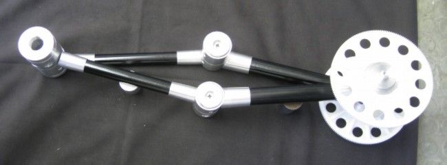
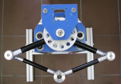
More assembly mockups:

Arms closed

Arms open

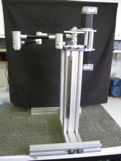
Then start on the support frame work to which the drive pivot mounts, as well as the two drive motors.
I am also working on an inductively heated hot-end as well as inductive heating of the print hot-plate. The Hot end prototype is very promising – using a heat treated/hardened silver steel nozzle with slightly extended rear in a tube form, around which a 20 turn, single layer coil, 15mm long fits. 13.54Mhz of RF is applied and 40 watts heats the nozzle to 400degrees in 18seconds, 200degrees in 7 seconds. I am using similar concepts as applied in the Metcal Soldering irons, also RF inductive tip heating, and measure SWR to the coil to regulate temperature – the SWR changes as the temperature changes, and the relationship is workable.
The hotplate trial are around a 3mm flat ( hopefully) steel plate backed by a close wound recangular, flat ( 1 Wire thick) coil, with 50 watts of 135kHz applied – so far the plate heats to 70deg C in 20 seconds and to keep it there seems to require about 12 to 15 watts. Heating seems to be pretty evenly spread as the coil covers the working area quite nicely- a max area rectangle of around 350mm x 250mm, with a much larger half circle.
Joe
Edited By Joseph Noci 1 on 02/02/2018 15:10:57<
 Neil Wyatt.

 , you can change the "offline cache time period (days)" to the maximum of 360 days. So it will work locally for up to that duration in the absence of an internet connection to its server. As SM says, it's best to think of the cloud as your backup rather than some sinister plot to acquire and flog off your IP.


