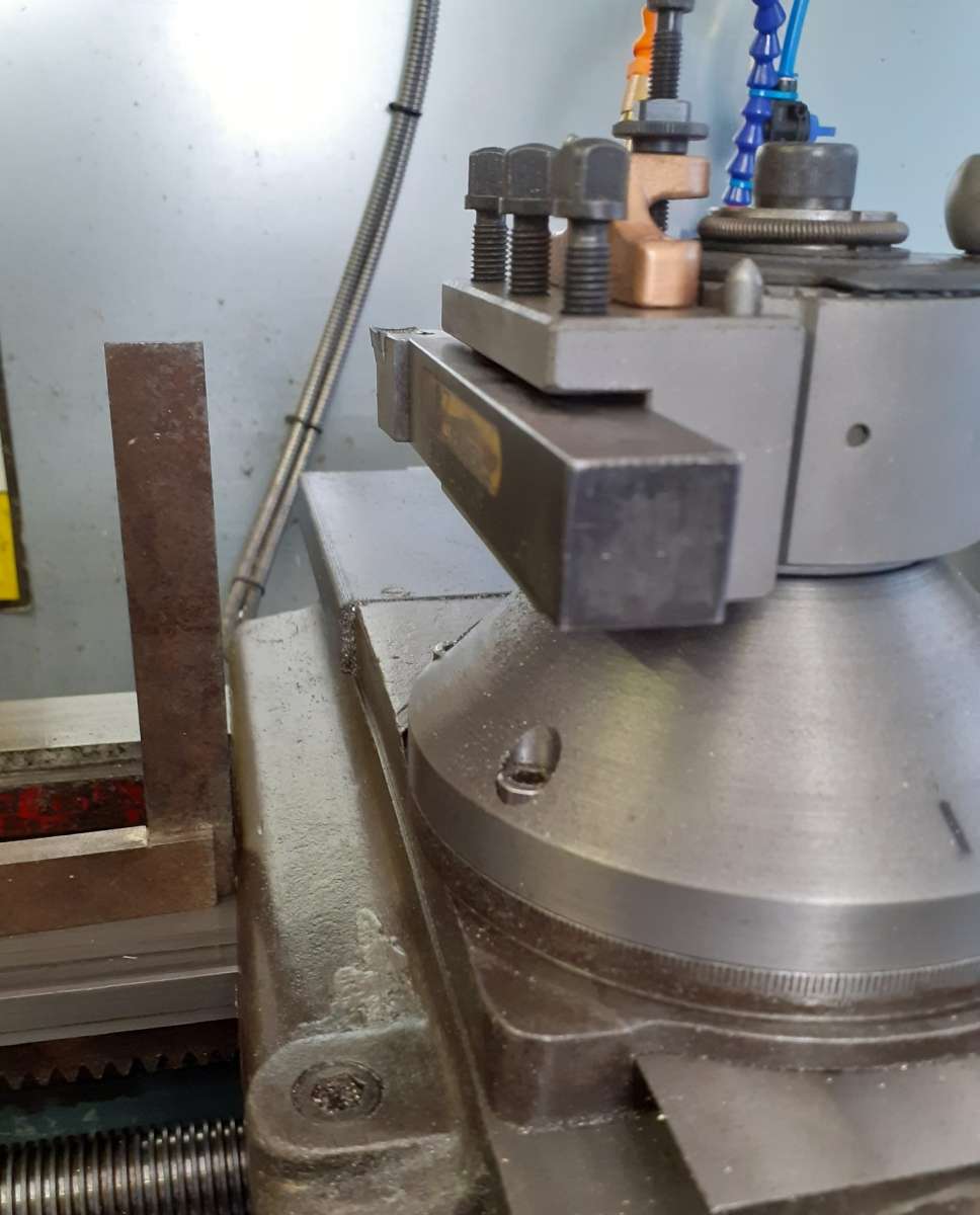
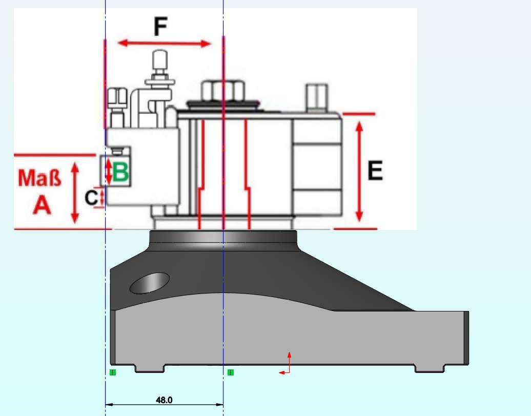
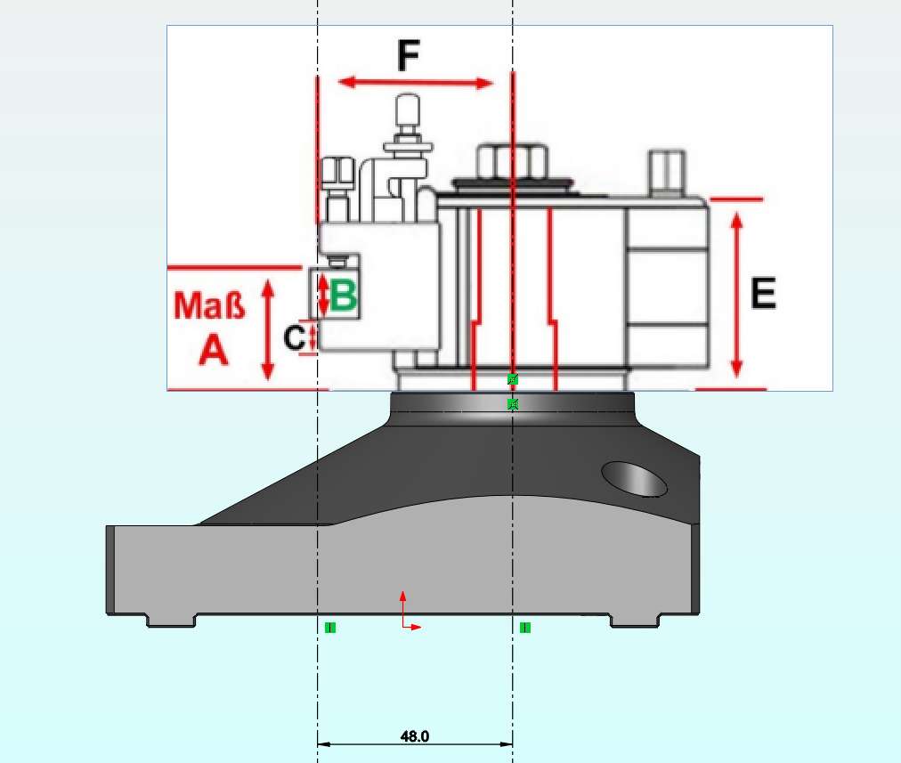
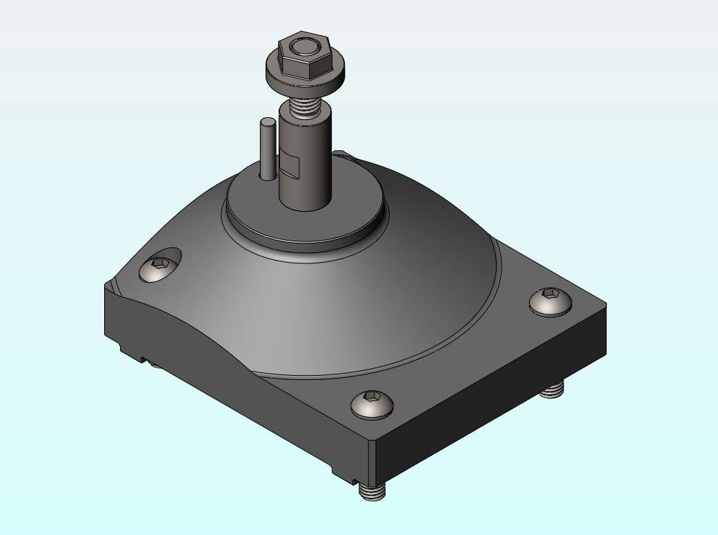
Design Advice!- Warco GH600 Solid Topslide
Design Advice!- Warco GH600 Solid Topslide
- This topic has 15 replies, 7 voices, and was last updated 27 March 2025 at 16:53 by
Richard Kirkman 1.
- Please log in to reply to this topic. Registering is free and easy using the links on the menu at the top of this page.
Latest Replies
-
- Topic
- Voices
- Last Post
-
-
Marlco knurler wheels
Started by:
 Pete.
in: General Questions
Pete.
in: General Questions
- 6
-
2 April 2025 at 01:37
Pete.
-
Tangential tooling
Started by:
Keith Matheson
in: Workshop Tools and Tooling
- 10
-
2 April 2025 at 01:29
Pete.
-
2 nice tools from temu
Started by:
Ian Parkin
in: Workshop Tools and Tooling
- 5
-
2 April 2025 at 00:59
Pete.
-
Forum Software?
Started by:
Vic
in: The Tea Room
- 2
-
2 April 2025 at 00:11
Vic
-
Powered hacksaw – blade lift for the return stroke
Started by:
Sonic Escape
in: General Questions
- 3
-
1 April 2025 at 23:51
Clive Foster
-
Which lathes have drawbars in the headstock?
Started by:
ell81
in: Beginners questions
- 9
-
1 April 2025 at 23:15
Peter Cook 6
-
Sulphuric Acid.
Started by:
Andrew Tinsley
in: General Questions
- 11
-
1 April 2025 at 22:19
noel shelley
-
DIY Pendulum Timer – GPS-Synced Beat Analyser
Started by:
Chris Raynerd 2
in: Clocks and Scientific Instruments
- 5
-
1 April 2025 at 21:14
Michael Gilligan
-
Hello from Kent
Started by:
michaeljf93
in: Introduce Yourself – New members start here!
- 7
-
1 April 2025 at 20:08
michaeljf93
-
Special BA bolts from Chronos
Started by:
old mart
in: Materials
- 3
-
1 April 2025 at 17:52
Greensands
-
Removing an advert (Myford SOLD)
Started by:
Tony Martyr
in: General Questions
- 2
-
1 April 2025 at 17:45
bernard towers
-
Bassett Lowke “Eclipse”
Started by:
JasonB
in: Stationary engines
- 6
-
1 April 2025 at 13:32
Jim Nic
-
Su251-53
Started by:
parovoz
in: Locomotives
- 9
-
1 April 2025 at 12:29
parovoz
-
Blue crystals. Probably not meth?
Started by:
pjbiker
in: Beginners questions
- 8
-
1 April 2025 at 11:46
Juddy
-
Generator size for vfd controlled 3 phase 5.5 kw motor
Started by:
PutneyChap
in: Electronics in the Workshop
- 9
-
1 April 2025 at 10:38
noel shelley
-
Unimat 3 / SL “T” nuts – off the shelf type
Started by:
rjenkinsgb
in: Manual machine tools
- 1
-
1 April 2025 at 10:25
rjenkinsgb
-
Beginner with newly bought lathe – many questions
Started by:
ell81
in: Beginners questions
- 14
-
31 March 2025 at 23:31
old fool
-
Clarke CL500M longitudinal feed screw
1
2
Started by:
Stuart Cox 3
in: General Questions
- 13
-
31 March 2025 at 20:42
john halfpenny
-
More Lidl questions
1
2
3
Started by:
old mart
in: Hints And Tips for model engineers
- 25
-
31 March 2025 at 19:45
Robert Atkinson 2
-
Lubrication of headstock bearings on a Clarke CL500M
Started by:
Howard Lyne
in: Manual machine tools
- 10
-
31 March 2025 at 19:37
old mart
-
Model Turbines
1
2
…
23
24
Started by:
Turbine Guy
in: Stationary engines
- 28
-
31 March 2025 at 14:47
Turbine Guy
-
HOBBYMAT MD65 – JAMMED
Started by:
David ANDREWS 2
in: Beginners questions
- 4
-
31 March 2025 at 13:36
Bazyle
-
What Did You Do Today 2025
1
2
3
4
Started by:
JasonB
in: The Tea Room
- 23
-
31 March 2025 at 13:25
Diogenes
-
RequiredOutside Diameter to Cut 5/16 BSF Thread
1
2
3
Started by:
James Alford
in: Beginners questions
- 24
-
31 March 2025 at 12:48
duncan webster 1
-
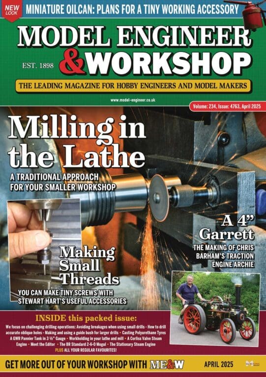
April issue ME&W
Started by:
edintheclouds
in: Model Engineer & Workshop
- 4
-
31 March 2025 at 12:44
edintheclouds
-
Marlco knurler wheels