Deformed plastic gear on milling machine

Advert

Deformed plastic gear on milling machine

Home Forums Manual machine tools Deformed plastic gear on milling machine

Viewing 25 posts - 26 through 50 (of 62 total)
  • Author
    Posts
  • #720691
    Bill Phinn
    Participant
      @billphinn90025

      A couple of edits:

      The diameter of the big cog is more like 87.6mm, rather than 88mm. Definitely not as small as 87mm, though, as Howard suggests.

      The observant may have noticed that the total thickness given in my previous post of 28.65mm is less than the sum of the two cog thicknesses and the width of the connecting/separating shaft by 0.4mm. I haven’t quite worked out why this is, but it may be something to do with the slightly raised area on the big cog, both on the upper surface (visible in my photo) and on the underside. Possibly this raised area is there to reduce friction against the gear shift paddle that sits between the two cogs.

      Advert
      #720692
      Michael Gilligan
      Participant
        @michaelgilligan61133
        On Bill Phinn Said:

        A couple of edits:

        The diameter of the big cog is more like 87.6mm, rather than 88mm. Definitely not as small as 87mm, though, as Howard suggests.

        Perhaps worth noting that some plastics [e.g.  Nylon] are hygroscopic, and growth on that scale would not be particularly unusual. … although, of course, your gearbox shouldn’t be damp!

        Conceptually … if the gearing is slightly oversize, but running on the ‘correct’ centres, it could run warm and therefore soften. [a situation which tends to escalate]

        MichaelG.


        #720696
        JasonB
        Moderator
          @jasonb

          Based on tooth count and it being a MOD gear diameters are likely to be (NoT + 2) x MOD

          Big gear 56 +2 x 1.5 = 87

          Small Gear 31 + 2 x 1.5 = 49.5

          #720699
          Michael Gilligan
          Participant
            @michaelgilligan61133

            … which makes ‘about 0.6mm’ on 87mm a reasonable amount of growth for a hygroscopic material, methinks.

            Perhaps more relevant though, is the fact that the small gear appears to have been only meshed to less than half its width.

            .

            IMG_9342

            .


            MichaelG.

            #720700
            JasonB
            Moderator
              @jasonb

              Yes that is what I said in my first reply

              #720703
              JasonB
              Moderator
                @jasonb

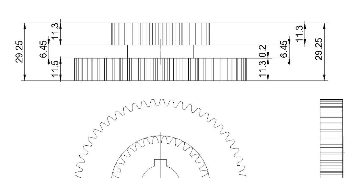
                11.3 + 11.3 + 6.45 = 29.05, in my book that is more than 28.65. I’ll draw it for you but need numbers that work.

                #720706
                DC31k
                Participant
                  @dc31k
                  On JasonB Said:

                  I’ll draw it for you but need numbers that work.

                  To reduce (or maybe a better term is to average out) measurement uncertainties, try to obtain ODs of the gears that mesh with this double gear and the shaft centre distance at which the meshing occurs.

                  Even if the centre distance is adjustable (like on a lathe banjo), it has to be the same for each pair.

                  That gives you a lot more data to work with.

                  It will not be possible to alter the shaft centre distance but the new gear could be made under- or over-size if the old one shows unsatisfactory engagement.

                  #720707
                  RobCox
                  Participant
                    @robcox

                    I’ve only just come across this thread, being one of those who visit less frequently since the site update.

                    Bill, have you sorted out getting your gear made? If not, I think I may be able to help you out here. I’ve made an attachment for my Elliott 10M shaper to cut gears, any DP, MOD and tooth count and it should be perfect for cutting the two gears as a single unit.

                    If you want to see more, (a bit of shameless self promotion here), have a look on youtube for ThePottingShedWorkshop, where I’ve posted some videos about it.

                    If you want some help, PM me and we can go from there.

                    Rob

                    #720717
                    Michael Gilligan
                    Participant
                      @michaelgilligan61133
                      On JasonB Said:

                      Yes that is what I said in my first reply

                      Well, of course you are always right Jason !

                      … I was simply illustrating the point with Bill’s own photo instead of a reference to someone-else’s disaster.

                      MichaelG.

                      #720794
                      Bill Phinn
                      Participant
                        @billphinn90025

                        Sincere thanks for everyone’s replies.

                        Michael, sadly I can’t tell whether or not the removed gear has expanded slightly from new (though Howard’s and Jason’s numbers suggest it may have done) because I baulked at paying Warco’s £60 for a probably short-lived replacement , so I have nothing to compare with.


                        On JasonB Said:

                        11.3 + 11.3 + 6.45 = 29.05, in my book that is more than 28.65. I’ll draw it for you but need numbers that work.

                        That’s right, Jason. I discussed this in my follow-up post (720691).

                        I don’t know how important the slightly raised areas are, nor how to describe them numerically, but maybe if the extra 0.4mm were distributed equally between the two cog thicknesses whilst preserving the given dimensions of the connecting/separating shaft there wouldn’t be too much of an issue. If I’ve read him rightly, DC31k does suggest a slight oversizing of the cog thicknesses may not be unhelpful.

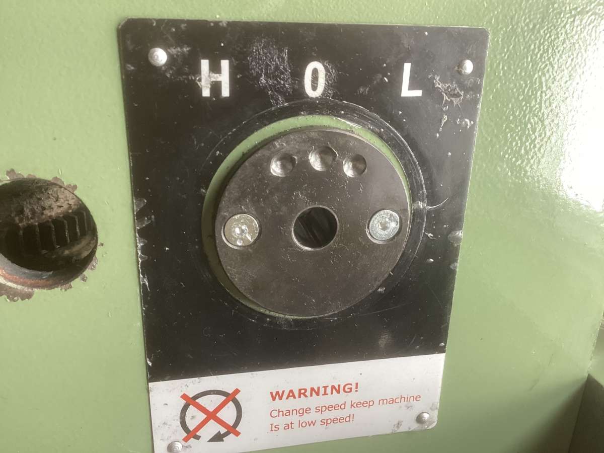
                        On this subject – the apparently only partial-thickness-engagement of the low gear with the spindle gear (both on my machine and on all the other examples I’ve seen on the Internet of the same stripped gear) – I’m wondering whether this may be something to do with the positioning of the detentes in the gear selector plate, rather than, or perhaps as well as, with the thickness of the cogs.

                        I’ll try to explain. After my gear was damaged but still in situ, I noticed that whilst the high gear sat perfectly level with the spindle gear when high gear had been selected, the low gear showed a tendency to drop back down slightly once the my hand let go of the knob and the ball bearing inside had settled back into its relevant detente.

                        It was not very easy to be sure of this, though, because the mangled portion of the gear made it difficult to select low gear at all. By way of explanation, in the photo at the foot of this post showing the circular gear selector plate, you will notice that the detente for the low gear is considerably closer to the central detente than the high gear detente is. Is this a factor in the unsatisfactory engagement, I wonder?

                        What I’m planning to do, assuming I get a new gear of some kind made and fitted, is to see what gear selection looks like with the new gear and the existing gear selector plate. If the new low gear visibly drops back down slightly away from full engagement when low gear is selected and the selector knob is released, I think I will know with more certainty that the detente position for the low gear isn’t far enough away from the centre to keep the gear in the correct alignment.  I will then set about making a new gear selector plate (probably from gauge plate) with the low gear detente countersink somewhat further away from the centre than on the present one.

                        Any further thoughts would be much appreciated.

                        Warco WM18 gear selector detentes

                        #720797
                        JasonB
                        Moderator
                          @jasonb

                          Bill, the post I took the picture from in this reply of mine went on to show a clamp that the guy made to lock his selector know in the fully engaged position as he too found that the selector and therefore gear worked the it way down. It was a bit rough but did the job. I will see if I can find it again.

                          If the existing plate is just held by those two screws you could just rotate it 180deg and drill some new detent holes.


                          If 29.45 Overall is OK I can easily put a 0.2mm raised area either side of the large gear or could reduce the central bos sto keep OA as 28.64 with the 0.2mm bearing. then you have the option to print or go elsewhere.

                          #720799
                          Dave Halford
                          Participant
                            @davehalford22513

                            On the detent plate, should it be a large diameter plate to give more authority. The detent lever on a Centec is much bigger.

                            The 2nd U tube link posted by Pete Greene from 6.00 to 6.04, where the guy actually tests the shift, the gear with the bad one that you can barely see, seems to move down as the gear is selected and up when not selected.

                            If the gear below is moving away under load and the detent is bad as well.??

                            #720803
                            JasonB
                            Moderator
                              @jasonb

                              Link to the thread I mentioned above with the locking lever.

                              #720805
                              DC31k
                              Participant
                                @dc31k
                                On Dave Halford Said:

                                On the detent plate, should it be a large diameter plate to give more authority.

                                Is it the size of the plate or the shallowness of the divots that is likely to be causing a problem?

                                I was just to post asking whether drilling through holes in the plate and using a pin-type locking mechanism might go some way to solving the problem.

                                Maybe it would be possible to remove the existing ball detent and spring, drill and tap the hole and use a long dog point grubscrew with outboard grip/knob to lock the lever into place.


                                #720807
                                Dave Halford
                                Participant
                                  @davehalford22513

                                  Don’t think a ball will work in a hole deeper than half the ball diameter.

                                  Thats a mans locking lever on Jasons link.

                                  #720883
                                  Bill Phinn
                                  Participant
                                    @billphinn90025

                                    Thanks a lot for the further replies.

                                    Jason, the overall thickness is 29.05, though as we’ve said the sum of the cog thicknesses and the connecting boss comes to 28.65. I don’t think adding a 0.2mm boss either side of the big cog to make up the difference would do much harm.

                                    Countersinking three new detentes on the opposite side to the present ones certainly seems like a time saver compared with making an entirely new plate, not least because it’s not just a round plate but a top-hat shape with an integral spigot that passes through the sidewall of the mill head.

                                    The thread about the Craftex mill makes for interesting reading. I’m not sure I’d opt for Brian Rupnow’s lever lock solution, though; it seems a bit cumbersome and, if I’ve understood things correctly, the locking pin/screw locates against the back of the motor cover, which is only plastic.

                                    Dave and DC31k, re your comments about the detente plate, I would say the plate is large enough for the purpose and the detente divots about the right depth (I’ve never known the mill to actually jump out of low or high gear); the problem with the gear selection, I suspect, if there really is one, is that the low gear detente isn’t sufficiently distant from the centre detente to hold the low gear in its correct position at the very top of the gear shaft; instead it appears to slip back down the shaft slightly as the ball locates in a poorly positioned detente.

                                    DC31k, a pin or dog point set screw in a hole rather than a ball bearing in a detente certainly seems like a more secure locating/retaining solution. I may well resort to this if I feel even a repositioned ball detente isn’t getting the low gear to stay where it belongs.

                                    #720897
                                    DC31k
                                    Participant
                                      @dc31k
                                      On Bill Phinn Said:

                                      I may well resort to this if I feel even a repositioned ball detente isn’t getting the low gear to stay where it belongs.

                                      Jason’s idea above about rotating the detent plate is a good one. Maybe you can put masking tape on it, reinstall the knob and mark the best postion for the three gear states.

                                      It could be that the OEM has assumed symmetrical about neutral and you might find that is not the case.

                                      Keeping the ball and divot is most ergonomic and once the position is established, it is easier to convert to a pin retainer than to go in the other direction.

                                      For info., there are calculations you can do on ball plunger retaining forces:

                                      https://www.vlier.com/german/product_index/sld/sel_06_diam.html

                                      #720912
                                      JasonB
                                      Moderator
                                        @jasonb
                                        On Bill Phinn Said:


                                        Jason, the overall thickness is 29.05, though as we’ve said the sum of the cog thicknesses and the connecting boss comes to 28.65. I don’t think adding a 0.2mm boss either side of the big cog to make up the difference would do much harm.

                                        11.3 + 11.3 + 6.45 = 29.05. not 28.65.

                                        11.3 + 11.3 + 6.45 + 0.2 + 0.2 = 29.45 overall not 29.05


                                        For the 3D printing option it would make sense to have the large gear 11.5mm with a 0.2mm raised area on the inner face only as having it on both will not be the best option to sit it flat on the printer bed. If needed mount the new gear on an arbor in the lathe and skim 0.2mm off to leave just the raised central area.

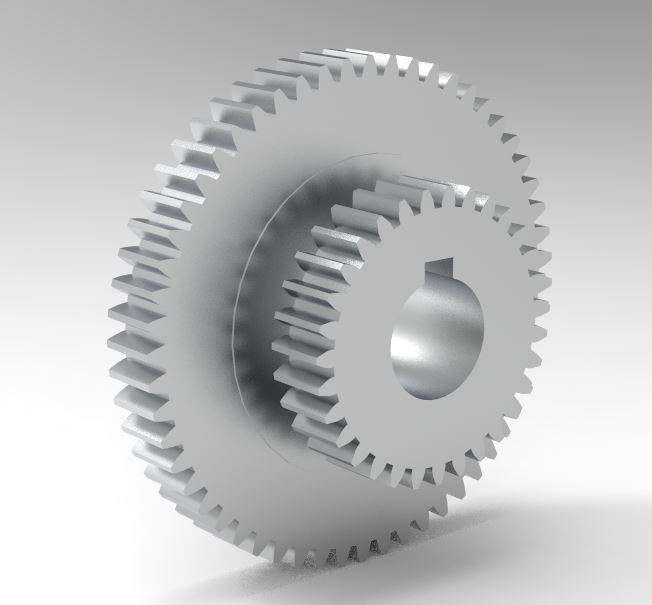
                                        Gear is drawn just waiting for confirmation of thicknesses.

                                        #720965
                                        Bill Phinn
                                        Participant
                                          @billphinn90025

                                          Thanks, Jason. I’ve clearly got things the wrong way round there. Sorry.

                                          Let’s assume the overall thickness is 29.05, consisting of a gap of 6.45 separating two gears that are 11.3mm thick just inside the point where the teeth begin, whilst the large gear has a raised area only on its inner surface of 0.2mm (extending to around half the diameter from the centre? – based on the picture of my gear and Brian’s gear).This makes the large gear both 11.5mm thick and 11.3mm depending on where you caliper it.

                                          If there is anything still wonky about these figures, do let me know.

                                          Edit: Just realised there is at least one thing wonky: to preserve the gap of 6.45 and have a thickened area of 0.2mm at the centre of the bigger gear, the overall thickness will be 29.25, not 29.05.

                                          DC31k, thanks for the further information. My initial idea was to mark the positions for the new detentes on a piece of card using a pair of compasses, using the locations of the high gear and central detentes as the guide for the new low gear detente position, and then prick punch through the card on to the plate. It may be safer though to do as you suggest and use the actual position of the gear knob to determine the correct location of the detentes for the three gear states. I’ve got transfer punches to go down the hole.

                                          #720972
                                          JasonB
                                          Moderator
                                            @jasonb

                                            Still can’t make it work out to 29.05

                                            If the top gear is a constant 11.3

                                            The Gap a constant 6.45

                                            And the large gear 11.5 when measured towards it’s middle

                                            Then total is 29.25

                                            Or

                                            If top is 11.3

                                            Gap 6.25

                                            Raised area 0.2

                                            And gear at it’s edge 11.3

                                            Total is still 29.25

                                            Neither is 29.05 or 28.64

                                            This is it dimensioned either way but total stays the same.

                                            bills gear


                                            #720980
                                            Bill Phinn
                                            Participant
                                              @billphinn90025
                                              On JasonB Said:

                                              Still can’t make it work out to 29.05

                                              total is 29.25

                                              Yes, I made an edit to that effect shortly before you posted. Sorry to waste your time there.

                                              #720999
                                              JasonB
                                              Moderator
                                                @jasonb

                                                OK, Message me an email address and I’ll send a file that can be used for printing if you decide to go down that route.

                                                bills gear

                                                #721512
                                                Pete Rimmer
                                                Participant
                                                  @peterimmer30576
                                                  On JasonB Said:

                                                  Based on tooth count and it being a MOD gear diameters are likely to be (NoT + 2) x MOD

                                                  Big gear 56 +2 x 1.5 = 87

                                                  Small Gear 31 + 2 x 1.5 = 49.5

                                                  worth noting here that Denford use a plastic 12DP gear in the headstock and they had to re-issue the drawing for that gear with extra clearance to allow for expansion. I believe that it was more for thermal expansion in use causing the gear to bind when it got warm than expansion from taking on moisture. The heat expansion would quickly run-away at high speed on my machine causing the gear set to bind in mesh and the gear selector to be tight until it cooled down.

                                                  #721520
                                                  Diogenes
                                                  Participant
                                                    @diogenes

                                                    Edit – redundant post – !

                                                    #727345
                                                    Bill Phinn
                                                    Participant
                                                      @billphinn90025

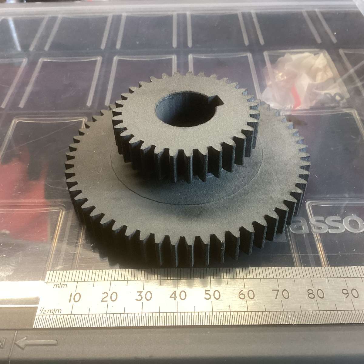
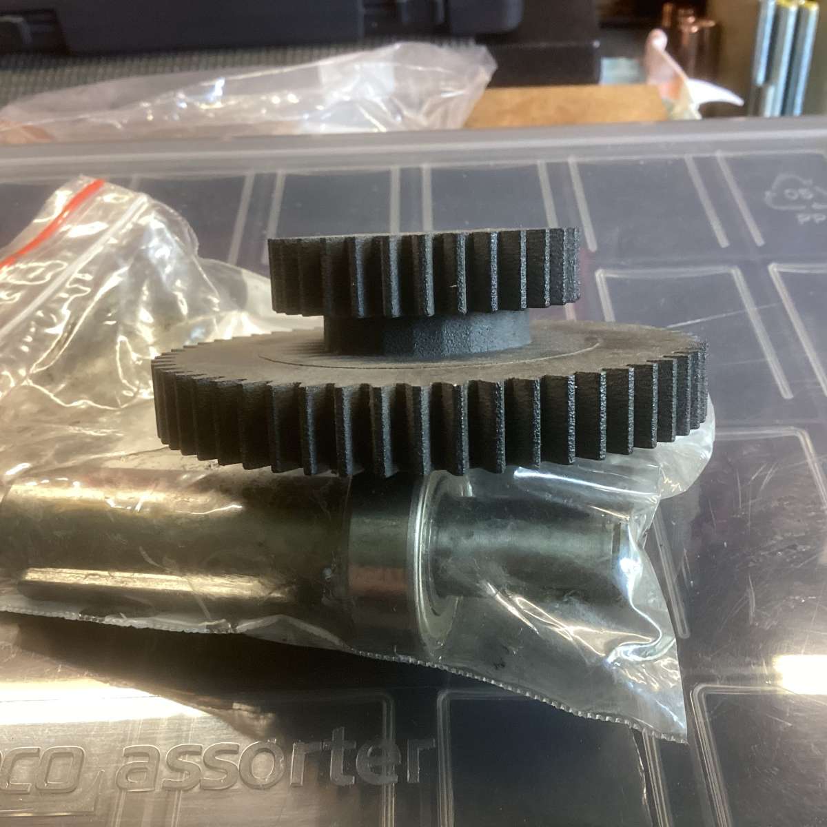
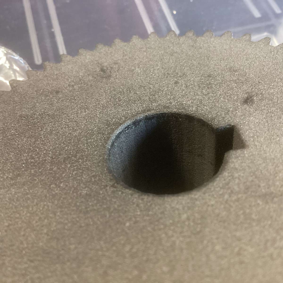
                                                      Just to update, I’ve received a newly made 3D printed gear from the print shop.

                                                      Apparently the material used is PA12. This is a form of nylon, I believe. I’m not sure how strong this is relative to other nylons or whether it’s the optimal plastic for a gear for this purpose. Unfortunately, I don’t know what percentage of infill has been used on my gear.

                                                      I’ve just watched a video of a test done by Youtuber Clough42. His results suggest that plastics such as ABS and certain nylons that people assume are a stronger choice for gears than the most commonly used printing plastic PLA may not actually be stronger than it and may in fact be weaker.

                                                      Anyway, I’ll have to fit the gear first and use it for a while before I can vouch for its durability.

                                                      Many thanks to everyone who generously offered me their help and advice.

                                                      IMG_0554IMG_0555IMG_0556

                                                    Viewing 25 posts - 26 through 50 (of 62 total)
                                                    • Please log in to reply to this topic. Registering is free and easy using the links on the menu at the top of this page.

                                                    Advert

                                                    Latest Replies

                                                    Home Forums Manual machine tools Topics

                                                    Viewing 25 topics - 1 through 25 (of 25 total)
                                                    Viewing 25 topics - 1 through 25 (of 25 total)

                                                    View full reply list.

                                                    Advert

                                                    Newsletter Sign-up