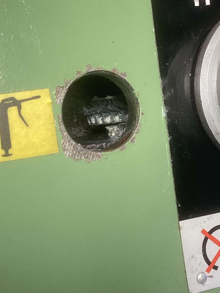
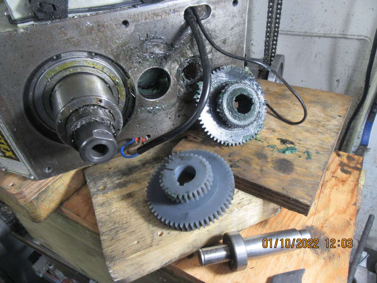
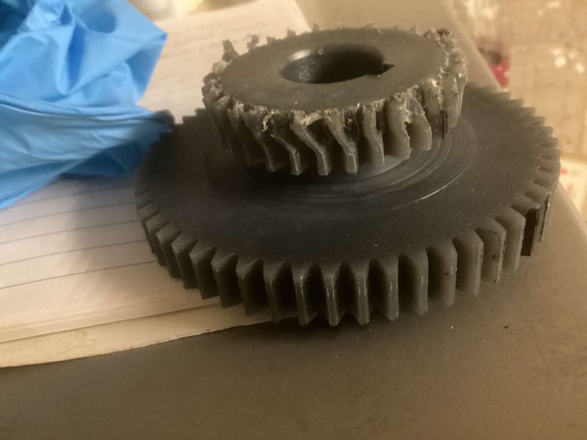
The teeth on the plastic gear that engages when low gear is selected on my Warco WM18 mill have deformed (like in the middle picture of post number 30) in response to an attempt to cut through some mild steel plate with a 22mm Rotabroach annular cutter.
Can anyone give me some tips on how to go about accessing and disassembling the gearbox to replace the damaged gear? The parts diagram with the mill doesn’t really give much help in this respect.
Probably be more bad luck if the motor or board let out some smoke if the gear had not failed first due to probably being overloaded.
Also when you do fit the new pair of gears make sure they engage fully and stay engaged when running. The gear in the photo looks like it has only been partly engaged as the lower part of the teeth are relatively straight and the upper 2/3rds or so damaged by the meshing gear. putting a heavy load through only part of the gears width is going to see it fair sooner than if all the width is taking the load equally.
Surely, these days it can’t be beyond the capability of the makers of electronics for such machines to include an intelligent overload protection system? Using the basis that the electronics catch fire or gears to strip just seem sledgehammer / walnut thinking. I cannot see cost as a justification for not doing it these days with incredibly cheap chips widely available for everything.
How happy might you feel if you stripped a plastic gear in your car’s gearbox every time you pushed it a bit hard – not very I suspect, hence the manufacturers don’t do it.
Plastic is a wonderful material in most applications, but not all IMHO
Perfectly true. But if the gear is losing full contact for whatever reason, surely the plastic is less likely to survive than a good quality metal job? I’m no materials expert, but it seems logical to me. The WM18 is a reasonable sized piece of kit (in hobby terms) and certainly not intended for ‘light’ work only.
Whilst I can appreciate the use of a sacrificial fibre gear in a lathe geartrain where catastrophic chuck/saddle type jams are perhaps not unknown, just using non-metal gears in the main drive of a mill seems to be more cost-based than sound engineering. Or am I just an old-school luddite? (probably)
Talking of sound engineering that is another reason the plastic gears are used they run quieter than metal on metal particularly when not fully meshed.
Yes plastic won’t survive as well as metal but it is what is next in line that could be damaged if it is replaced with metal which may be more costly like a cooked motor or board.
I think the old luddites tended to make use of the vee belts slipping if something was overloaded not so easy with a metal gear on the motor shaft of this machine. Those equiped with toothed belts may strip the belt but at least they are easier to get at than buried plastic gears.
Peter G., your links have got me started nicely. I just need a chunk of time (and a new gear) to attempt the job now. Given my domestic circumstances, workshop time isn’t something I get much of, unfortunately.
Pete R., that’s very generous of you, and I’ll certainly pay you for your time and materials if you do it. However, as Jason says, it’s a combi gear (high and low together), so it may be a bit of a headache to make on manual machinery. I’m afraid I’ve never cut even a single gear in my life myself so wouldn’t know where to start.
Another idea is 3D printing (in some sort of plastic of course). This would preserve the plastic gear’s overload protection function. I would, however, have to buy a new plastic gear from Warco first, presumably, in order to provide a perfect model for the scanner to read. Maybe I’m wrong there and you can input dimensions into a 3d printer manually as well as by scanning, though I would imagine this involves more work at the very least. Just for the record, a replacement plastic gear from Warco will cost me just shy of £60 with delivery. I would also have to buy a 3D printer as well if I then wanted to print a spare!
Jason, you’re quite right about the partial meshing of the teeth in the photo, which of course shows someone else’s gear, not mine. I’ll try to take a photo of mine later, but essentially on mine only the upper half of the teeth are pushed over, so either there was incomplete meshing to begin with (in spite of the detentes on the gear selector knob never having given me any trouble) or the initial stages of the overload caused what were fully meshed gears to jump apart just at the point where full engagement was most needed.
From Internet searches, it’s apparent that stripping out the low gear is a common occurrence on the WM18 type of mill (also sold by Grizzly and Amadeal I think, among others). One Youtuber says he has had three failures of the same gear since he bought the mill.
I had already successfully broached 1/2″ thick aluminium on the mill using the same Rotabroach 22mm cutter without any issues. When it came to my first attempt broaching some mild steel (10mm thick hot rolled in this case) I knew there would be more strain on the mill than when cutting aluminium, but the cutter was sharp as a razor (having only ever cut through two 1/2″ thick pieces of aluminum in its life), was run at 180 rpm, was copiously lubed, and I was certainly not pulling down hard on the quill because I’m physically incapable of doing so with the right arm I’ve got.
At the moment of failure there was no drama, just a scarcely audible click and then no rotation of the cutter. I wasn’t actually aware that the gear was plastic until this point. On the one hand I’m grateful it was only plastic, for reasons others have pointed out; on the other, it looks like it’s going to be a bit of a physical challenge to get things apart and the new gear in.
It’s at this point that I regret not waiting another year before buying a mill, because a year after I bought my WM18 Warco brought out a belt drive version.
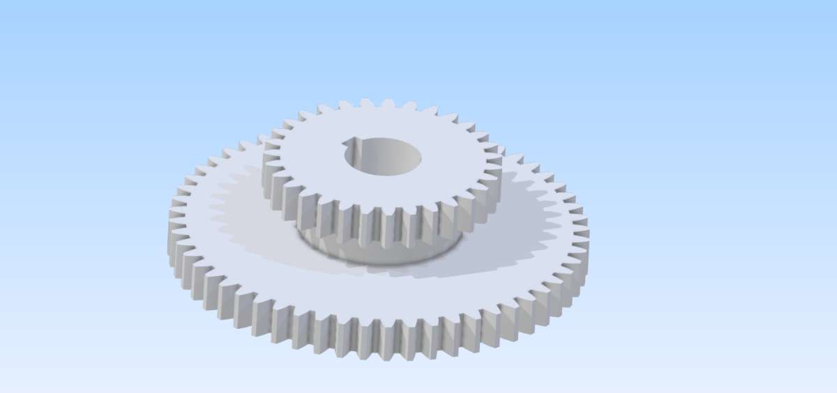
If going down the 3D printed route then they are likely to be standard MOD gears so a bit of tooth counting and OD measuring should give enough info for them to be drawn in CAD and then printed in a suitable plastic.
Edit the photo is not showing at the moment but may do later.
EDIT 2. What is the OD of the larger gear as the manual gives the tooth counts as 62 & 42
It would be worth counting the teeth on the meshing pair as a double check as the PCD of each pair should be the same. I count the gears on this photo of a similar gear is 32/56
I would also have to buy a 3D printer as well if I then wanted to print a spare!
If you want a ‘perfect model’, you will need a scanner costing in excess of the replacement cost of ten milling machines.
As has been said, calculate the engineering data for the gear and measure other dimensions. 3D modelling programs are available form zero cost upwards that will produce a file suitable for 3D printing.
You do not need a 3D printer. You need a contact with a 3D printer to make a prototype. Then, once you have confirmed your 3D model is correct, send the file to a commercial 3D printing service such as JLCPCB. They have machines and materials that a home-shop person can only dream of.
Peter G., your links have got me started nicely. I just need a chunk of time (and a new gear) to attempt the job now. Given my domestic circumstances, workshop time isn’t something I get much of, unfortunately.
I had much the same circumstances until very recently …. now it’s hard to get going again.
On my lookalike mill I stripped the gears once – but more often (quite frequently in fact) I blew the machine’s fuse. When these machines were first imported here, the local electrical authority would only give type-approval if a lower value fuse was fitted …. and it was very sensitive.
In the end, I fitted the original fuse spec and made up a special wall-outlet with circuit breaker which is easy to reset. That worked out much better. Then I installed a belt-drive from a kit and that was an incredible improvement. No stripped gears and so-o-o quiet!
I agree with some of the comments above; the plastic gears are there purely due to cost, nothing to do with a fail safe mode. A properly designed drive train should survive the motor being stalled without damage. As mentioned, in the event of a stalled motor, electronic drives should be able to detect and deal with that at minimal cost.
In the past Jasonb kindly edited and posted a video of me overloading my horizontal mill. As expected the geared drive survived without incident.
Caveat: Stalling the motor is not the same as a crash. For instance if you run a tool into the chuck on a lathe, and shock load the drive train, you will almost certainly cause damage irrespective of whether the machine is hobby or high end industrial.
I will obviously have to get the old gear out before I can make much progress.
My wife’s university has a 3D printing facility that will do work for staff including work “in metal”; you have to pay only for the materials, apparently. I may send the gear in that direction when I get it out.
Getting to grips with 3D modelling software myself is certainly on my to-do list, but having never had a lesson in any aspect of IT in my entire life I’m unlikely to have got to grips with 3D modelling sufficiently to create a file that will produce the gear within any sensible time frame.
It seems it’s a double win for the supplier then, who first saves on manufacturing costs and then charges a surely handsome mark-up for the frequently demanded replacements.
Once sizes are known I expect a member may offer to draw it for you. One of the reinforced plastics may be a good halfway house between metal and just plastic.
Andrew doing some light work on his A&S as I mentioned belt slip is what often happens on the older machines with vee belts and stops the motor stalling even though the spindle has stopped, you can hear the squeal.
I’m not convinced it is just cost, it would have been cheaper to fit a couple of pullies and a belt from the motor to gearbox input on the OP’s machine yet they chose steel gears and they could have had the gear that mates with the damaged one also in plastic but again went for more costly metal.
I also don’t think it is purely a fail safe even though it is often the bit that fails due to overload, if a gear had been intended as the failsafe then I would have thought either the one on the motor or the one it mates with would be the best option as they are easier to get at and replace.
Noise reduction is one reason and some “compliance” to allow for any slight deviation in shaft PCD may also come into play as to why a plastic gear was chosen.
Is it me or on the 2nd U tube link posted by Pete Greene from 6.00 on, where the guy actually tests the shift, does the meshing gear that you can barely see, have a touch of vertical float?
Interesting how they all (so seen) seem to fail on half engagement.
Might be worth checking the gear select detent is working as it should. If it’s OK then consider that the plastic gear is unsuitable for the load applied and it’s deforming under that load. I have an unused 30mm Rotabroach with about a 4mm width of cut. I would have thought that was a huge load on a gear train.
if a gear had been intended as the failsafe then I would have thought either the one on the motor or the one it mates with would be the best option as they are easier to get at and replace.
I’ve not taken the motor or its mounting plate off yet, but from what I’ve seen on Youtube of very similar mills to mine the larger gear the motor gear mates with is typically plastic.
I’m beginning to wonder whether the low gear ever did engage fully with the spindle gear from new and whether this heightened the chance of failure not just for me but for lots of similar mill owners out there.
This is the 3D printing facility I may be allowed access to.
Any thoughts on the suitability of the various choices on show there?
Concrete might be low on the list.
Right now, you have produced no dimensions nor sketch of the item you want, so your question is moot.
On the page to which you link, you will see that they offer advice on which process will produce an item to suit your engineering needs and budget. Send them the model and see what they say.
I was thinking of a carbon fibre reinforced Nylon which would be printed by the FFF or FDM type printers as stronger than a warco replacement but not as noisy as metal.
I wonder if that initial gear would fail first if the other were in full mesh?
I was thinking of a carbon fibre reinforced Nylon which would be printed by the FFF or FDM type printers as stronger than a warco replacement but not as noisy as metal.
Noted, Jason. It looks like that’s an option they offer.
I wonder if that initial gear would fail first if the other were in full mesh?
Possibly, yes; they certainly do fail at times, as evidenced by this video. Now that I’ve got the motor and mount plate off and electrical connections undone I see that that gear (the transfer gear) on my mill is indeed plastic.
It looks like the guy in the video also replaced his high/low gear (the one that’s failed on mine) for a new plastic one shortly before he made the video on replacing the transfer gear. Maybe I should get a transfer gear done as well as a high/low gear in reinforced nylon while I’m at it. I wish it was the transfer gear that had failed; it would have been a lot less faff to replace.
I’m just waiting for some 30mm box section steel to arrive (to make a frame for some sort of bearing pusher) before tackling the high/low gear extraction.