Death of a PSU

Advert

Death of a PSU

Home Forums Electronics in the Workshop Death of a PSU

Viewing 25 posts - 1 through 25 (of 36 total)
  • Author
    Posts
  • #487482
    Robin Graham
    Participant
      @robingraham42208

      I've had a dead SINO DRO unit on my shelf for years. I'm trying to upgrade my mill to glass scales, so thought I'd have another look at the display unit as I'd been told the most common failure with these devices is the PSU. So maybe an easy fix.

      And so it turned out – the display works fine with an external 5V supply.

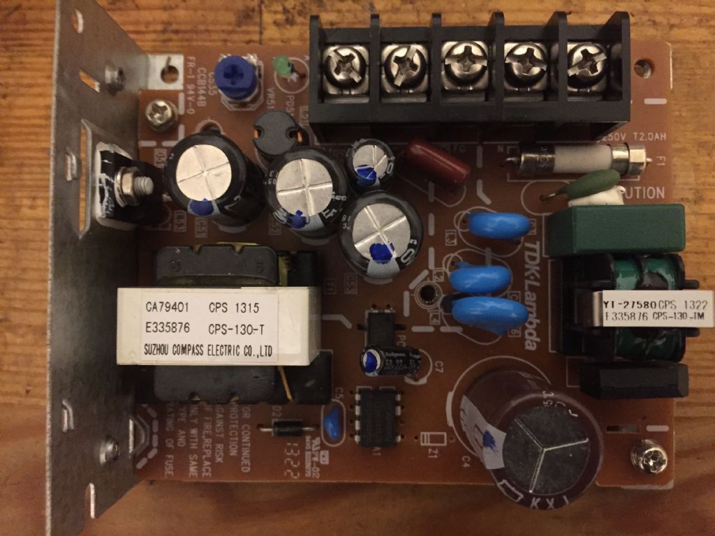
      My question (to which I think I might know the answer, but have to ask) is whether it is worth trying to repair the PSU. This is what it looks like:

      sinopsu.jpg

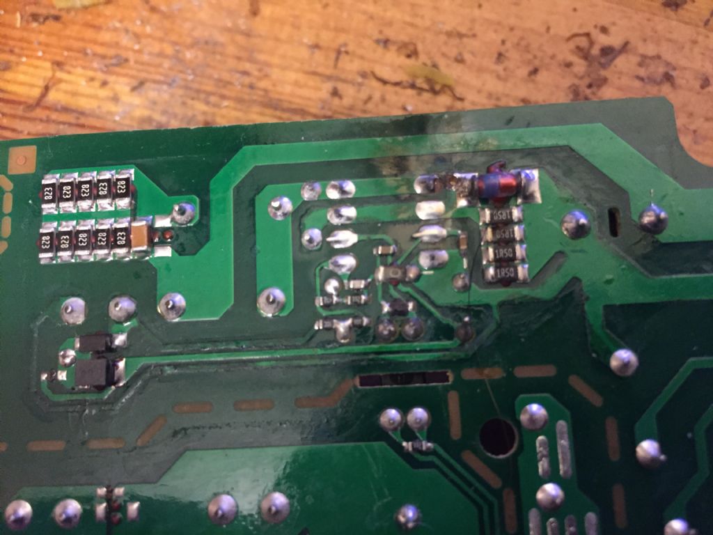
      The fuse under the connector block is open circuit and something's clearly gone wrong with the component marked Z1 to the left of the capacitor at the bottom of the pic. From the underside:

      pcb_underside.jpg

      I can get a slot-in replacement unit for 20 quid, so that's what I'll probably do – but I'd be interested in any info from the electronics bods on this forum about the possibility of repair and the probable reason for failure.

      Robin.


      Edited By Robin Graham on 25/07/2020 00:33:22

      Advert
      #32116
      Robin Graham
      Participant
        @robingraham42208
        #487493
        Joseph Noci 1
        Participant
          @josephnoci1

          Most of those types of converters are designed to a price and the integrity of the design around the switching device, any related snubber network and the excess voltage ratings of devices is cut to the bare minimum to save the pennies. So, even relatively benign conditions, a spike or surge on the mains line, perhaps from the powering one/off of the attached machines drive motor, etc can cause higher than normal voltage spikes on the switch devices and pop..Another killer is heat – In your supply the main switch device is on a reasonable heat sink, but in many instances the rest of the parts tend to be underrated , especially electrolytic capacitors – they tend to 'dry' out internally – rather, the electrolyte may dissipate from the active surfaces in the cap, and the cap becomes ineffective, loses capacity, becomes higher impedance.

          I believe in your supply, the controller is the 8 pin DIP package device – the other nearby seems to be the feedback optocoupler.

          I suspect the 8 pin device, the controller, is dead as well – the burnt pcb track on the underside connects to that device and for the track to burn like that implies that device went short circuit. That would most likely have been caused by the main switch – the device on the heatsink – having gone short circuit to start with – if it were only that switch, it might have been worth trying a repair, but it will now be multiple devices dead, and maybe electrolytics that need replacing

          In a repair of such converters you don't really get much chance to measure around with a 'scope or meter when debugging and replacing parts – any non-working part in the mains input side of the converter chain invariably results in, as a minimum , letting the magic smoke out on switch-on, or a big bang, with money down the drain each time..

          Toss it and get another

          Joe

          #487503
          Anonymous

            Given that the DIL is actually 7 pins I expect it's a custom chip that won't be available, even from the likes of Farnell and RS. I'd agree with Joe, bin it.

            Andrew

            #487512
            john fletcher 1
            Participant
              @johnfletcher1

              I'm no expert but wouldn't an 5 volt ex computer ex computer power supply be OK ? or in fact any 5 volt DC psu John

              #487515
              John Haine
              Participant
                @johnhaine32865
                Posted by Andrew Johnston on 25/07/2020 08:59:01:

                Given that the DIL is actually 7 pins I expect it's a custom chip that won't be available, even from the likes of Farnell and RS. I'd agree with Joe, bin it.

                Andrew

                Or was 8 pins before it blew?

                #487519
                Mike Poole
                Participant
                  @mikepoole82104

                  Interesting that it has TDK lambda printed on the circuit board who usually make high quality PSUs, a 5v 2A psu from eBay is about £6.50 which at that price makes fixing it barely worth the trouble but fixing it will also be satisfying and make a contribution to reducing our electronic waste mountain.

                  Mike

                  #487524
                  mgnbuk
                  Participant
                    @mgnbuk

                    Or was 8 pins before it blew?

                    From a close look at the pictures, I would say not. The solder covering the vacant hole in the pcb looks to be undisturbed.

                    Nigel B.

                    #487525
                    Joseph Noci 1
                    Participant
                      @josephnoci1

                      I am sure that device is a one of the SANKEN STR-A6000 series – available from Digi-Key for example – $2.00

                      See datasheet –

                      But – $2.00, another $3-4.00 for the power FET, maybe $3 – 4.00 for electrolytics, maybe the schottky rectifier post-switcher is also blown…$ could be $10.00 or more to repair, and maybe only works second time round..

                      The terminal block and input XR rated caps are useful – the rest is scrap!

                      dc_dc converter.jpg

                      #487526
                      Joseph Noci 1
                      Participant
                        @josephnoci1
                        Posted by john fletcher 1 on 25/07/2020 09:47:39:

                        I'm no expert but wouldn't an 5 volt ex computer ex computer power supply be OK ? or in fact any 5 volt DC psu John

                        Absolutely – I suppose the problem is that the replacement has a place it needs to fit into, and unless the proposed PC supply is of small form factor, it would be to big..

                        Not sure what the current requirements are for the DRO – If Robin could read off the controller's part number we can see from the data sheet which chip it is and what the supposed wattage it is capable of.

                        Joe

                        #487528
                        Anonymous
                          Posted by John Haine on 25/07/2020 10:24:59:

                          Or was 8 pins before it blew?

                          Looking at the underside there's no evidence that a pin was ever soldered in the location of the missing pin. I've seen a lot of fudged ICs, but never seen a pin missing without leaving evidence of the failure. smile

                          Andrew

                          #487532
                          Kiwi Bloke
                          Participant
                            @kiwibloke62605

                            Difficult to see from the pix, but is Z1 a rather chunky SMD, mounted on the underside of the board, and has it failed? Sometimes, Zeners run too hot because a higher current version should have been specified. Can you discover its voltage? At least there are holes in the pcb, so it might be worth soldering in a new one – easy, as it doesn't need to be a fiddly SMD, given the holes. Gotta be optimistic!

                            #487536
                            Les Jones 1
                            Participant
                              @lesjones1

                              The TNY264 is also a 7 pin low power switch mode regulator chip. It would be nice to know the part number of the chip on the board as the picture is not good enough to read it.

                              Les.

                              #487538
                              Chris Shelton
                              Participant
                                @chrisshelton11794

                                The space made by the missing pin is for isolation.

                                #487546
                                Anonymous
                                  Posted by Chris Shelton on 25/07/2020 12:08:13:

                                  The space made by the missing pin is for isolation.

                                  That's the theory; it should provide creepage and clearance between the switching waveform and a low voltage supply that powers the IC. But look at the tracking on the underside of the PCB – completely negates any isolation obtained from the missing pin.

                                  Andrew

                                  #487547
                                  Joseph Noci 1
                                  Participant
                                    @josephnoci1

                                    Well, we are not going to repair this thing with all our guessing, but the fix will for sure NOT be just a zener replacement!

                                    The PCB track is blown away, it is no more, not even nailed to the PCB anymore…and that track is the feed between the 400VDC ( from the large cap) and into the transformer, then on to the FET. The many 1206 SMD resistors top left 2nd pic are all current sense from the FET switch. The ONLY reason for the blown track is that the FET switch is a short now…which then often shorts drain to gate, which places 400VDC onto the control chip gate driver which pops it which….

                                    Joe

                                    #487554
                                    Anonymous
                                      Posted by Joseph Noci 1 on 25/07/2020 12:41:29:

                                      The many 1206 SMD resistors top left 2nd pic are all current sense from the FET switch.

                                      I think they're part of the primary winding snubber?

                                      I can't tie up the layout with the Sanken datasheet, so I don't think the IC is the one shown on the datasheet.

                                      #487555
                                      Neil Wyatt
                                      Moderator
                                        @neilwyatt

                                        I'd buy a cheap replacement to fit, and snarf enough bits to cover the difference in price between that and a possible dodgy repair.

                                        SMPSUs are the one broken bit of electronics I avoid bodging.

                                        Neil

                                        #487561
                                        Robert Atkinson 2
                                        Participant
                                          @robertatkinson2

                                          For a small single output SMPS like this any kind of high energy failure, e.g blown tracks or exploded components, makes them poor candidates for repair. Just replace it. with the same or similar. The induced currents and voltages from a high energy failure can damage multiple components. You can change the obvious ones on have it go bang first time you switch it on. Less obviously compoonents may have been stressed making future failure more likely.
                                          Faultfinding on this type of supply needs caution and a good understanding of high voltage hazards.

                                          Robert G8RPI.

                                          #487617
                                          Robin Graham
                                          Participant
                                            @robingraham42208

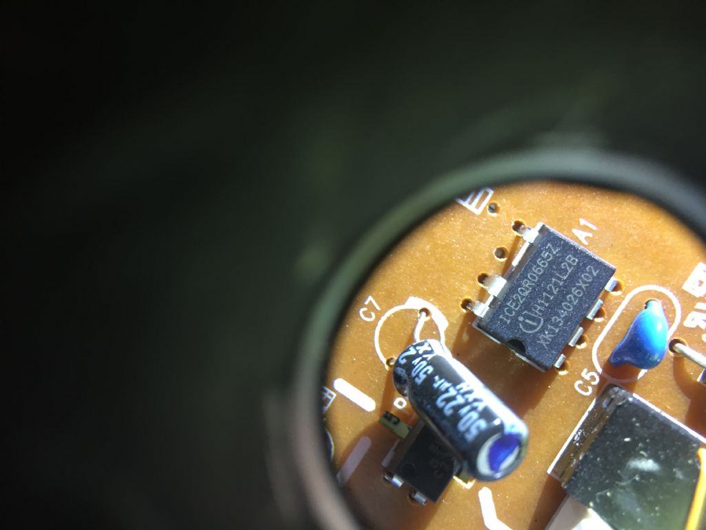
                                            Thanks for replies. It sounds like the unit is beyond economic repair, as I suspected. Out of interest though, here is the 7-pin chip in more detail:

                                            img_2357.jpg

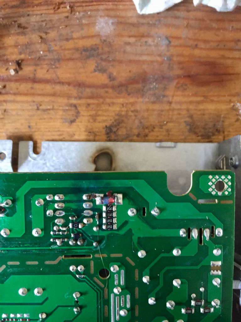
                                            and the site of explosion:

                                            fullsizerender.jpg

                                            The unit is rated 5V 7A – the plate on the DRO gives a power rating of 25VA.

                                            I actually have a cheap 5V 10A psu which would do the job but, as Joseph correctly guessed, the problem is the size. The existing unit (TDK-Lambda CS35-5) is 3.9×3.2×1.4 inches – the replacement from RS I'm looking appears to be a direct replacement. As far as I can tell from my researches, the CS35-5 is no longer available having been superseded by LS-35-5.

                                            If anyone can point to a cheaper alternative which would fit, that would of course be welcome!

                                            Robin

                                            #487637
                                            duncan webster 1
                                            Participant
                                              @duncanwebster1

                                              Does it have to be internal? Put the PSU you've got on a flying lead and mount it externally, it's not as ig a DRO display needs to be terribly portable

                                              #487650
                                              Joseph Noci 1
                                              Participant
                                                @josephnoci1

                                                Robin, can you see what the part number is of the device fitted to the metal bracket/heatsink?

                                                Andrew is correct – the many resistors are a snubber, the current sense resistors are the ones at the burnt pcb track.

                                                This PSU is a quasi-resonant topology, and for the power rating indicated by Robin, unlikely that there is an external FET switch.

                                                It does appear that the arcing on the PCB may just have been due to poor layout – the tracks a little close at that point, and maybe some dirt developed that precipitated the arc.

                                                If you want to perhaps waste some money and time….

                                                The diode next to the arc point might have blown – I believe that is a zener regulating the the supply line to the VCC input the the 8pin chip. The current sense pin and the drain pin on the device are very close, made worse by the pcb track layout, and those two pins have full rectified line voltage between them.

                                                So, if the zener diode is blown ( would probably be a short) , replace, and replace the 8pin device – available maybe from Digikey , Mouser, maybe even RS components, CLEAN the pcb well and give it a try!

                                                Below is a reference circuit for the supply – this one is a 20volt output, but I am pretty sure the the circuit is close enough.

                                                Interested to know what that device on the heatsink is..

                                                Good luck!

                                                Joe

                                                ice2qr0665 dc_dc.2.jpg

                                                #487652
                                                not done it yet
                                                Participant
                                                  @notdoneityet

                                                  My initial thought was that likely all the components on the board could be replaced for twenty quid – and even any tracks repaired on the board. But even doing that might not be successful….

                                                  I would likely do as Duncan suggests – screw a suitable power supply to the wall and run some curly lead across to the unit – unless a cheaper (reasonable quality) unit, that fitted the space, could be sourced.

                                                  #487764
                                                  Robin Graham
                                                  Participant
                                                    @robingraham42208

                                                    Joe, it's not easy to see the markings on the component but as far as I can make out there are two lines – top LT 1117 and bottom MBRF2045CT.

                                                    Thanks for posting the schematic. If I have a go at repair, what voltage Zener would I want? Presumably the 22V in the schematic is to do with it being a 20V supply? I am

                                                    Ta for the suggestions of mounting the PSU externally – the unit I have is the chassis mount (ie not fully enclosed) type, and I was thinking that by the time I'd bought a suitable enclosure and associated gubbins it'd be getting close to the cost of a new unit. But on second thoughts, maybe I could lash something together from stuff I've already got.

                                                    Robin.

                                                    #487766
                                                    Robert Atkinson 2
                                                    Participant
                                                      @robertatkinson2

                                                      The enner voltage has nothing to do with the output voltage. It s tere to protect the IC from voltage spikes (If R3 was more than 0 ohms it could be a regulatrd supply for the IC). Note that the circuit cannot be totally correct for the supply you have as it is using multiple surface mount components that are not showm on the circuit.
                                                      The failure appears to be on the un-isolated part of the circuit. While I would normally encourage any one to attempt a repair, even if not really economic, for the learning experience, an mains SMPS is noot a safe place to start learing about electronics. No disrespect, but from the questions you are asking, you almost certainly do not have the knowledge or equipment to safely repair this power supply.

                                                      Robert G8RPI.

                                                    Viewing 25 posts - 1 through 25 (of 36 total)
                                                    • Please log in to reply to this topic. Registering is free and easy using the links on the menu at the top of this page.

                                                    Advert

                                                    Latest Replies

                                                    Viewing 25 topics - 1 through 25 (of 25 total)
                                                    Viewing 25 topics - 1 through 25 (of 25 total)

                                                    View full reply list.

                                                    Advert

                                                    Newsletter Sign-up