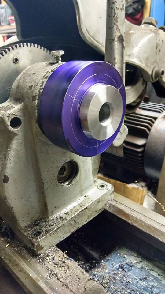
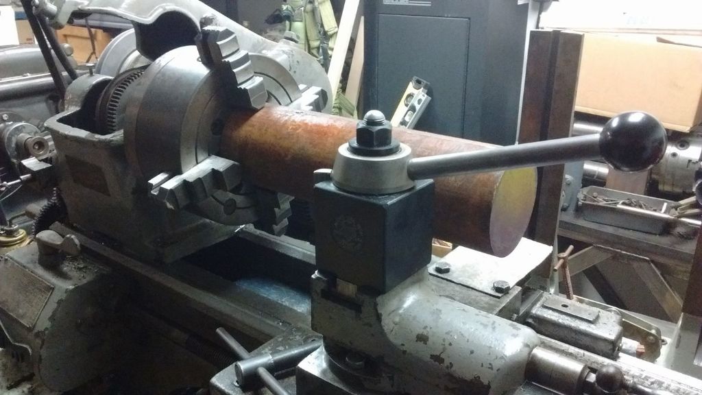
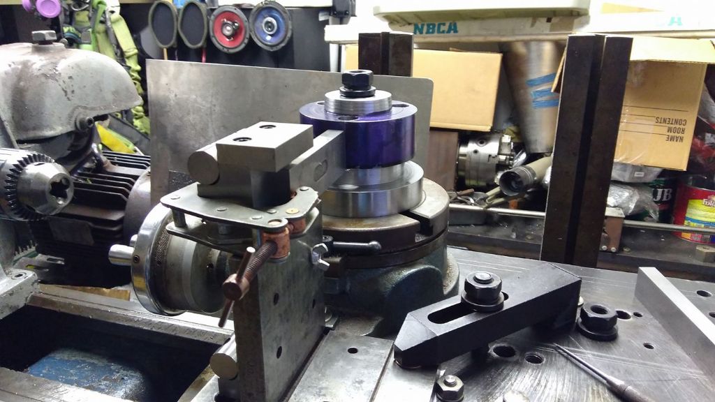
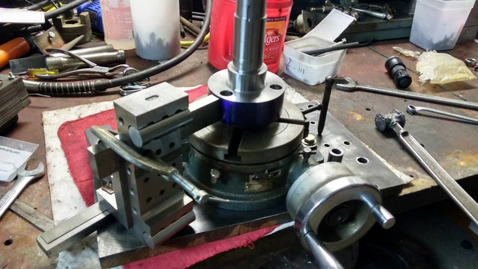
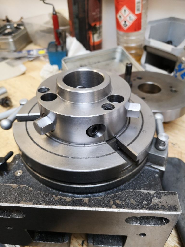
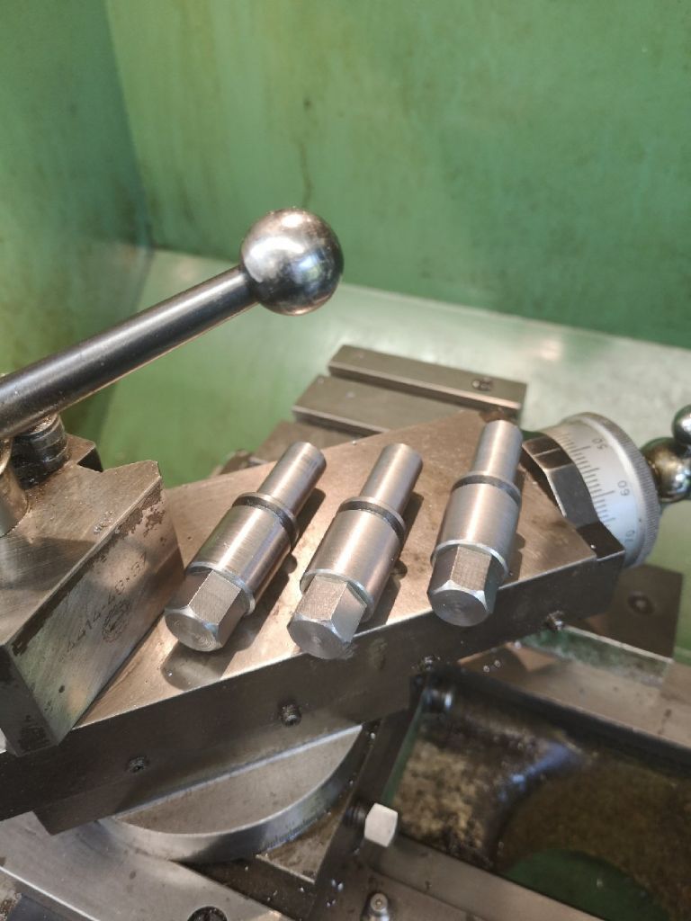
Having just bought a rotary table with a controller attached, the idea of being able to move chucks direct from the lather to the rotary table appealed. I read this post and exchanged notes with Murray and set to. My design is based on the standard but differs from Murray's in that my rotary table only has three slots which makes things easier, I also put hexagon heads on the cams but stayed closer to the standard stop bolt orientation to keep the height of the adaptor to a minimum. I did not bother making the spring loaded stop bolt arrangement but could add this later I suppose.

The standard is not so easy to use as it gives design detail for the full range of cam lock spindles but you can puzzle it out.
I came across another post questioning the design of the cams themselves so I thought it might be useful if I shared my understanding and the method of making them.
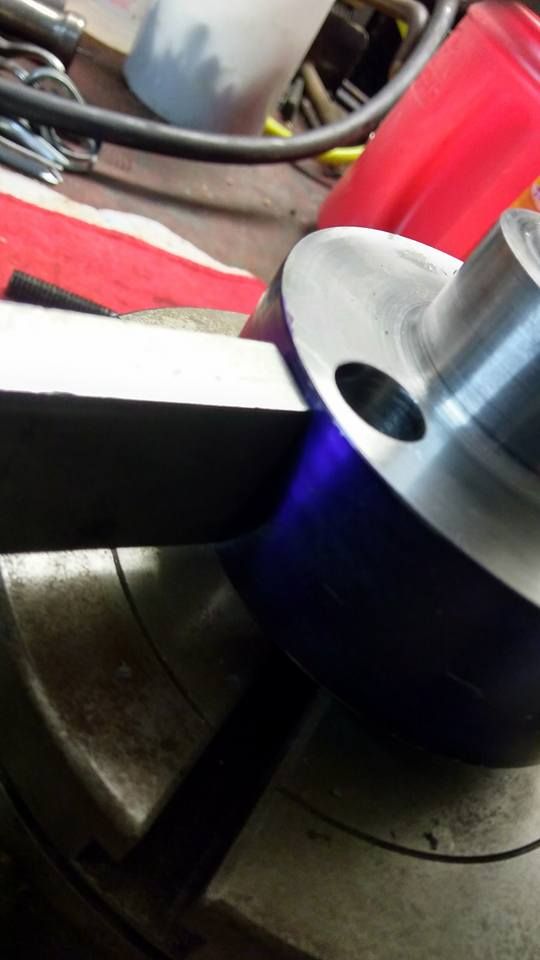
The first question was about the cam profile and the angle "v" on the standard. I am on the same page as Murray here and believe that the cam profile is in fact a circle – with a bit of geometry you can work out that for the D1-3 cam the diameter of the cam portion is 0.677" and it is eccentric to the body of the cam by 0.031". The angle "v" on the drawing essentially shows that the required cam action occurs over this angle, the dimensions "d" and "e" tell you the extent of the cam action. having made them to this scheme I can confirm that it all works fine.
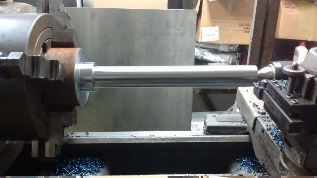
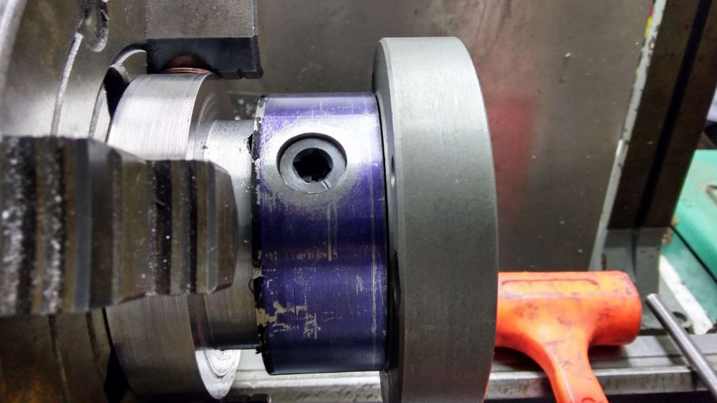
When it comes to making them I started with three blanks featuring a chucking piece on the inboard end of each blank. The outboard end is extended versus the standard to take the hexagon rather then the square hole as specified.

I have a smallish 3 jaw chuck with a large hexagon shaped lump on the back in place of a back plate – I use this in the milling machine to put the hexagons on.
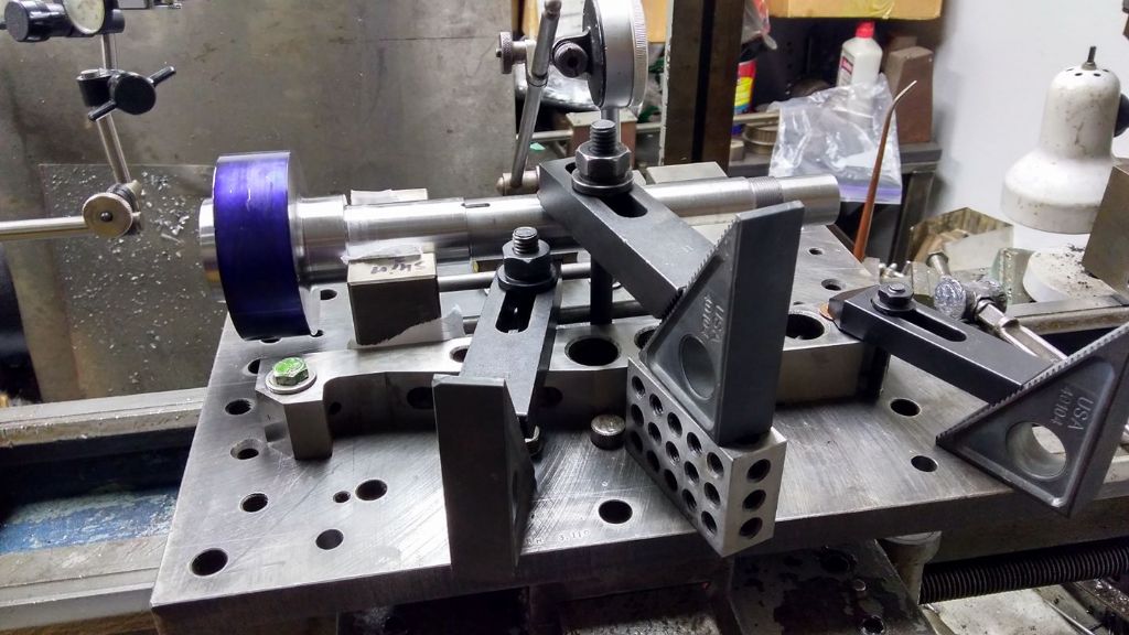
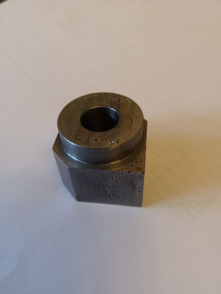
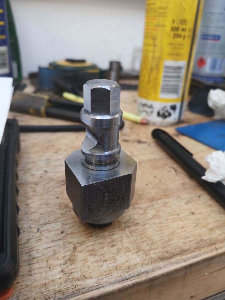
Next I made up a little jig block that in based on a square but has a hole for the chucking piece through it offset by the required 0.031" eccentricity. It also has a register at the same eccentricity to allow it to be held in the 3 jaw to turn the eccentric cam. I also added flats on the block at 45 degrees to facilitate the later machining of the 45 degree feature.
Let me just add a photo of that….
Nealeb.


