Cylinder Boring Techniques for Steam Engines

Advert

Cylinder Boring Techniques for Steam Engines

Home Forums Beginners questions Cylinder Boring Techniques for Steam Engines

Viewing 25 posts - 201 through 225 (of 286 total)
  • Author
    Posts
  • #101910
    Will Robertson
    Participant
      @willrobertson16447

      Thank you very much – postage is much faster and cheaper from UK than USA (oddly, German suppliers can sometimes be funny about posting to Switzerland).

      A sort-of abrasive question: Tubal Cain said in Model Engineer 19 March 1993 p318 "What, you may be asking, about using an "O" ring? Frankly I don't recommend these in an iron cylinder. Even with the utmost care there is always risk of a rust film – as much with compressed air as with steam. This fine film embeds into the ring material, and acts as a lap, both on ring and cylinder. The ring stops rolling as it should and you soon find leakage."

      I've thought over these words a lot and the more I think about them the more I conclude that Tubal Cain was right – rust is hydrated iron oxide which is also used as jewellers' rouge abrasive for polishing. It would probably embed itself in softer plastics. What are your thoughts? Would Tubal Cain's advice apply to PTFE (Teflon) piston rings as well as to rubber o-rings?

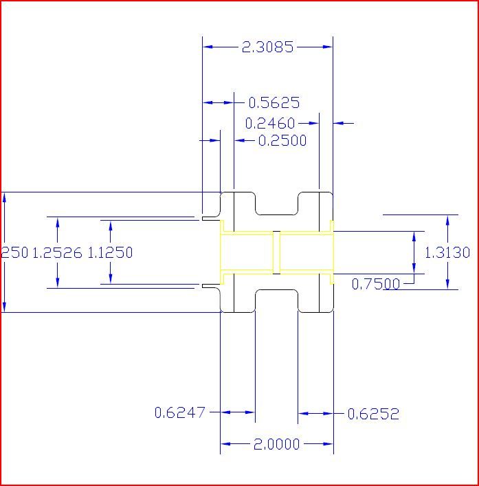
      Here are the first of the plans – in this case for the cylinder heads for the engine. I exported them from DraftSight in JPEG format which is the only format that this site allows images to be uploaded in and I thought might be the easiest format for people to view. They aren't as clear as I'd like and it's necessary to right click, view image then zoom in a bit (Ctrl key and scroll middle mouse button) to read them (the colours also appear faded after uploading so it's difficult to tell the difference between white lines and grey layout lines). They look much clearer in SVG format.

      **LINK**

      Will

      Edited By Will Robertson on 25/10/2012 21:37:33

      Edited By Will Robertson on 25/10/2012 21:43:39

      Advert
      #101922
      JasonB
      Moderator
        @jasonb

        I've never run o rings or teflon in an iron cylinder so can't comment except to say there wa sobviously a reason they were not specified on the iron cylindered engines that I have made.

        Two comments on the drawings.

        1. cylinder covers (not heads) look very thick, its not dimensioned but the bolting flange looks to be 6mm thick where 2.5 – 3.0mm would be quite adequate on a 30mm dia cover, also the spigot going into the cylinder can be shorter as well.

        2. your drain cock holes will leave the hole in the middle of the cock above the base of the cylinder, move them down and cut a notch in the spigot like you have done for the steam port.

        J

        #101967
        Will Robertson
        Participant
          @willrobertson16447

          Hi Jason,

          I'd seen o-rings in cast iron cylinders in designs online and people had reccomended them – it looks though from your experience as if Tubal Cain was right and they're a bad idea in cast iron cylinders.

          Thank you. I haven't bought the drain valves yet but I measured one of the oilers (which is about hte same sise) and moved the holes forf the drain valves down by 1mm.

          I have to admit that there was a reason I made the cylinder covers and the flanges so thick and didn't dimension them – it was so that I could make the piston valve assembly longer without it looking out of place and give myself a bit more flexibility with the layout of the piston valve assembly. If I increase the stroke from 30 to 32 or 34 mm and move the steam ports a little that will let me reduce the sise of the flanges. The two pistons on the valve spool are each 10mm long at the moment – that was to allow me space to add piston rings to the piston valves in the future – do you reckon I'll be OK if I reduce the length of each piston in the piston valve to 6 or 8mm?

          Will

          #101979
          Will Robertson
          Participant
            @willrobertson16447

            Sorry – another question – how much should the piston of the piston valve extend over the steam port when the valve is at the end of its travel? At the moment I've designed the piston valves so that each piston in the piston vale overlaps the steam ports by 2mm at the end of its travel (2mm diameter steam ports and a 4mm travel for the valve). I've posted a sketch of the current design for the piston valves with the other diagrams: **LINK**.

            #101991
            JasonB
            Moderator
              @jasonb

              Not done anything with piston valves so can help on this one.

              J

              #101994
              Terryd
              Participant
                @terryd72465
                Posted by Will Robertson on 26/10/2012 21:41:45:

                Sorry – another question – how much should the piston of the piston valve extend over the steam port when the valve is at the end of its travel? At the moment I've designed the piston valves so that each piston in the piston vale overlaps the steam ports by 2mm at the end of its travel (2mm diameter steam ports and a 4mm travel for the valve). I've posted a sketch of the current design for the piston valves with the other diagrams: **LINK**.

                Hi Will,

                Like Jason I have never built an engine with piston valves but I note that at least one of Elmers engines use them – like this one, so it might be an idea to look at those and work out what he allowed.

                Regards

                Terry

                #102011
                Will Robertson
                Participant
                  @willrobertson16447

                  Hi Jason and Terry,

                  Thank you for the plans for the Elmers engine – it looks like he's ended up in the same situation as me – the piston valve cylinder ends up a little longer than the main cylinder. I'll compare his design with Greenly's. If anyone knows of any other designs that I can look at for ideas please let me know.

                  I'll use the idea of oil groves in the piston vavles from the Elmers design (I'll maybe add piston rings in the future if I get a chance).

                  Will

                  #102122
                  Will Robertson
                  Participant
                    @willrobertson16447

                    I thought I'd put the design of the piston valves to one side temporarily and look at the design of the piston for the main cylinder. I've uploaded the diagrams of my attempts to design possible pistons to the existing album here:

                    **LINK**

                    I did different designs for pistons for brass/bronze/gunmetal cylinders and for cast iron cylinders.

                    The text in red on these diagrams is where I'm asking advice because I'm unsure about some of the dimensions. I find the text fairly difficult to read with the diagrams in JPEG format – it this is a problem please let me know and I can email them over in SVG format (which most modern browsers can read, which can be zoomed in/out without loss of clarity and where the text is much clearer).

                    Will

                    #102127
                    JasonB
                    Moderator
                      @jasonb

                      Can't read a thing, PM sent

                      #102131
                      Will Robertson
                      Participant
                        @willrobertson16447

                        Hi Jason,

                        Thank you very much. I've emailed you the diagrams in SVG format which is much clearer and allows effective zooming in/out.

                        Will

                        Edited By Will Robertson on 28/10/2012 19:44:28

                        #102134
                        Mustafa B. Adday
                        Participant
                          @mustafab-adday34743

                          Might be a good idea to change background color in drawings to white!

                          Mustafa

                          #102184
                          Will Robertson
                          Participant
                            @willrobertson16447

                            A quick question about modern end mills and slot mills:

                            Traditionally, I thought that an end mill could cut moving sideways but could not cut moving downwards (plunge-cutting). Slot mills by contrast could plunge-cut and cut moving sideways. When I buy a modern 4 flute HSS end mill, two of the four blades on the end join at the centre so it looks like it's centre cutting and designed for effective plunge cutting. Am I correct in thinking this?

                            Will

                            #102185
                            JasonB
                            Moderator
                              @jasonb

                              You need one of the teeth to go past the centre.

                              J

                              #102226
                              JasonB
                              Moderator
                                @jasonb

                                Having seen your piston drawings these are my thoughts:

                                Couple of thoughts on the pistons

                                1. I've not used teflon but I don't think the 20.5mm dia ring will compress down to the 20mm bore

                                2. The way you have shown both halves of the piston threaded M5 is not good. If using a 5mm piston rod the turn the end down to 4mm and thread M4. Drill the thin part of the piston 4mm and tap the stepped part M4 and fit a M4 locknut. This way the two parts will be pulled up tight against the sholder as the rod is screwed in.

                                3. The whole piston looks quite long, at least reduce the two 4mm flanges to 3mm, if needed you can put some clearance in the cylinder cover to clear the locknut.

                                4. For a brass cylinder you can make the piston from bronze, CI or aluminium.

                                5. The cast iron rings are much to thick, halve them to 2mm x 1.5mm or less

                                6. No need for the solid ring between the two split ones

                                7. How do you propose to cut the 45deg joint and spring the rings

                                8. I would just split the rings straight across and snap stretch them
                                over the piston which can then be a singel piece rather than two
                                piece.

                                J

                                #102227
                                Clive Hartland
                                Participant
                                  @clivehartland94829

                                  The piston going onto the rod has to be free of 'Cant' so Jasons idea of a shoulder will allow a true surface to make sure the piston and rod are in the same line.

                                  Having just had the that fault on my little engine meant I had to make two new pistons and rods. my further ideas would have been to put the rod almost through the length of the piston using its diameter to keep it true and have a short thread only and loctite As it was, my pistons were only 5mm so it was not possible so stuck to the shoulder on the rod.

                                  Clive

                                  #102399
                                  Will Robertson
                                  Participant
                                    @willrobertson16447

                                    Hi Jason,

                                    Thank you very much. Here are my replies to Jason's points (originally sent by email but put on here in case anyone wants to correct me on anything or has anything to add.)

                                    1) Yes – I'm uncertain about that as well – the design and dimensions came from a model builder here – the design is very similar to one that's used for hydraulic cylinders. I've got a fair-sised piece of PTFE (Teflon) stock so I can afford to get it wrong a few times and have to re-make them.

                                    2) I wondered about that – it didn't 'feel' right – I'll change to the way you recommended. Should I use an M4 coarse or M4 fine thread? (Maybe I should go for M4 fine just for uniformity since most of the rest of the engine seems to have ended up using fine threads.)

                                    3) Yes – the whole piston is 10mm long – I'll reduce the length as you suggested.

                                    4) Is stainless steel not suitable for the piston in a brass cylinder? – I wasn't sure. Ideally I'd make a gun metal (bronze) rather than brass cylinder but a friend gave me a big chunk of brass stock so I felt that I should use it. I've become more and more interested in cast iron and in the future I'd like to make an engine with cast iron cylinder and piston but I'll avoid cast iron in this particular engine to keep it rust-free. I'm usually sceptical of aluminium in a steam engine because I'm concerned that contact with air and hot steam may cause it to build up too thick an oxide layer and jam – but this comes from school chemistry not engineering experience.

                                    5) Thanks – I'll halve the thickness of the cast iron rings.

                                    6) Thanks – I was following Greenly on this but I noticed that hydraulic engineers often didn't have a solid ring between the split ones.

                                    7) For the PTFE (Teflon) with a scalpel and a good light. For the cast iron I have no idea but I hoped that somehow I'd manage to find out along the way or that someone would tell me (maybe using a slit saw or a very sharp and very carefully positioned chisel?).

                                    8) Thanks – I didn't know how springy cast iron was – I'll give that a try – it makes sense since it's how internal combustion engine pistons and rings are made.

                                    I've updated the drawings with Jason's suggestions.

                                    Hi Clive,

                                    Thank you very much – I remembered the problems you'd had and left part of the piston un-threaded but it was only a small part and probably wouldn't have been enough. I think I got the idea that I could thread perfectly true from the design of the S50 but the more I think about it the more I realise that a tapped thread is always likely to be a less true than a turned or bored surface.

                                    Do you have any views on whether the thread in the piston should be metric fine or coarse?

                                    I apologise for sending SVG files with my plans by email and having only unclear images on here. I'm looking at ways to put clearer images online so that everyone can give their thoughts.

                                    PS – I had a quick look in Greenly and he agrees with you both re. joining the piston and piston rod.

                                    Will

                                    Edited By Will Robertson on 31/10/2012 19:25:03

                                    #102403
                                    JasonB
                                    Moderator
                                      @jasonb

                                      Will, if you export it as a PDF then when its on your screen use the snipping tool to capture the pdf image and that can be saved as a jpg and posted here.

                                      Edited By JasonB on 31/10/2012 20:10:34

                                      #102404
                                      Clive Hartland
                                      Participant
                                        @clivehartland94829

                                        Hi Will, just standard threads, in mine it was M2.

                                        Re the Bees, The Daily Mail said today that overall in the UK the Honey harvest was 82% down. An idea of what that means to a beekeeper is a hive that normally gives 30lb , this year only gave 8lb. beekeepers say it was the weather at the beginning of the year that stopped the bees working but does not explain why I took 200lb plus off three hives.

                                        Dire warnings of price rises for honey.

                                        Clive

                                        #102457
                                        Will Robertson
                                        Participant
                                          @willrobertson16447

                                          Hi Jason and Clive,

                                          The problem turned out to be that the forum software was compressing the JPEG images and that was causing the text and a lot of the other detail to become illegible

                                          I've uploaded the next set of drawings (the main cylinder) to here where they're not compressed

                                          **LINK**

                                          I reckon that the final 12.8mm drill leaves too much stock to be removed – I think I might have found a larger drill though. Ideally, what sise should I drill to ready to bore to 20mm diamiter?

                                          JPEG is designed for photographic images (JPEG stands for Joint Photographic Experts Group) and isn't good with technical drawings. SVG (Scalable Vector Graphics) is much better for drawings so I can upload them in that format as well if it would help.

                                          Sounds like a mixed situation re. honey production – it maybe depends on the skill of the individual beekeeper and local weather variations.

                                          Will


                                          Edited By Will Robertson on 01/11/2012 14:15:06

                                          Edited By Will Robertson on 01/11/2012 14:42:33

                                          #102464
                                          JasonB
                                          Moderator
                                            @jasonb

                                            You can leave out stages 1&2 and go straight in with the larger centre drill.

                                            If boring I would likely drill it 5/8" (16mm) but the 12.8mm will be OK if thats all you have.

                                            No need for any cutting fluid with brass, maybe a bit when drilling the bronze but not needed when boring.

                                            Will see what this comes out like when you enlarge it by clicking on the image, thats done as I described above from Draftsight.

                                            front hub.jpg

                                            Edited By JasonB on 01/11/2012 16:14:11

                                            Edited By JasonB on 01/11/2012 16:15:14

                                            #102897
                                            Will Robertson
                                            Participant
                                              @willrobertson16447

                                              Hi Jason,

                                              Sorry to go quiet for a few days – friend visiting.

                                              I saw that you used a white background for your drawings – I reckoned that I should do likewise but i couldn't work out how to change the background colour of an existing drawing in DraftSight – I tried Tools > Options > System options > Display > Element Colours > Sheet Background but the sheet background seems to already be set to white – whatever I change it to the background on the drawing displayed on screen stays black. I must be doing something really daft…

                                              Will

                                              #102899
                                              JasonB
                                              Moderator
                                                @jasonb

                                                Use the default black background as its easier on the eyes.

                                                When you export it as a PDF it will change it to black on white same as it does when you print it.

                                                J

                                                #102913
                                                Will Robertson
                                                Participant
                                                  @willrobertson16447

                                                  Ahh – OK – now I understand…

                                                  DraftSight seemed to default to a text sise of 0.2 – which was far too small so I doubled it to 0.4 – which still seems too small – should I just ignore the default and keep increasing the text sise until it looks reasonable? I couldn't find a way of changing the text sise for all text in a layer or drawing at once (I can change the colour of all the elements in a layer easily but I can't find a way of changing the text sise of all the elements in a layer or drawing).

                                                  Will

                                                  #103085
                                                  Will Robertson
                                                  Participant
                                                    @willrobertson16447

                                                    I've been trying to get the cylinder of the S50 mounted in a 4 jaw chuck so that I can get the bore sorted out but things aren't going according to plan. The 4 jaw I'm using was modified at some point in the past (not by me) by welding metal blocks onto the 4 jaws. The metal blocks aren't perfectly true and the distance between two of the 4 jaws varies by 0.28mm between the front and the back of the chuck. I'm not sure how to handle this – in the past I've always relied on assuming that the jaws of a chuck are near enough perfectly true.

                                                    I know that I need to have at least one jaw which is true so that I can put the valve face against it and use that as datum. The hole in the centre of the 4 jaw is too large to allow me to use the back of the chuck as datum. The jaws of the chuck are a little shorter than the cylinder so I'll need to use some soft metal between the jaws and the cylinder to hold the cylinder as well as to avoid marking it.

                                                    I tried taking off the jaws and cleaning the surfaces they ran on to make sure it wasn't any loose swarf causing the problem but that didn't help. I also had a look at buying a new chuck but CTC only do 3 jaw. Not sure what to do. I could maybe ask someone else who has a 4 jaw if I could use theirs.

                                                    #103087
                                                    JasonB
                                                    Moderator
                                                      @jasonb

                                                      If its just steel welded to the jaws a bit of quality time spent with your file and a square will be most rewardingsmile

                                                    Viewing 25 posts - 201 through 225 (of 286 total)
                                                    • Please log in to reply to this topic. Registering is free and easy using the links on the menu at the top of this page.

                                                    Advert

                                                    Latest Replies

                                                    Home Forums Beginners questions Topics

                                                    Viewing 25 topics - 1 through 25 (of 25 total)
                                                    Viewing 25 topics - 1 through 25 (of 25 total)

                                                    View full reply list.

                                                    Advert

                                                    Newsletter Sign-up