Cylinder Boring Techniques for Steam Engines

Advert

Cylinder Boring Techniques for Steam Engines

Home Forums Beginners questions Cylinder Boring Techniques for Steam Engines

Viewing 25 posts - 126 through 150 (of 286 total)
  • Author
    Posts
  • #98218
    Will Robertson
    Participant
      @willrobertson16447

      Hi Clive,

      Thanks for the photos of your beautiful engine.

      Thank you for your advice re. silver solder. I saw some paste silver solder and thought that it would be ideal for soldering the valve gear to the cylinder. When I saw the price (100 francs) I had to reconsider. Can anyone recommend a good place to buy this in smaller quantities at a more affordable price? (My memory from electronics was that paste solder always had a 'best-before' date so it was best to buy little and often rather than keeping a large stock for a long time.) For aesthetic reasons I'm trying to avoid bobby solder marks around where the cylinder and valve gear join which I think I might get if I use silver solder wire and flux.

      An o-ring would be good for the head – better than gasket paper – I'll look into that in more detail.

      Hi Jason,

      Thanks for the link to the liquid gasket you use. I'll order some. It's not perfectly authentic but life's too short to fiddle around with gasket paper and I did enough of that when I was a child anyway.

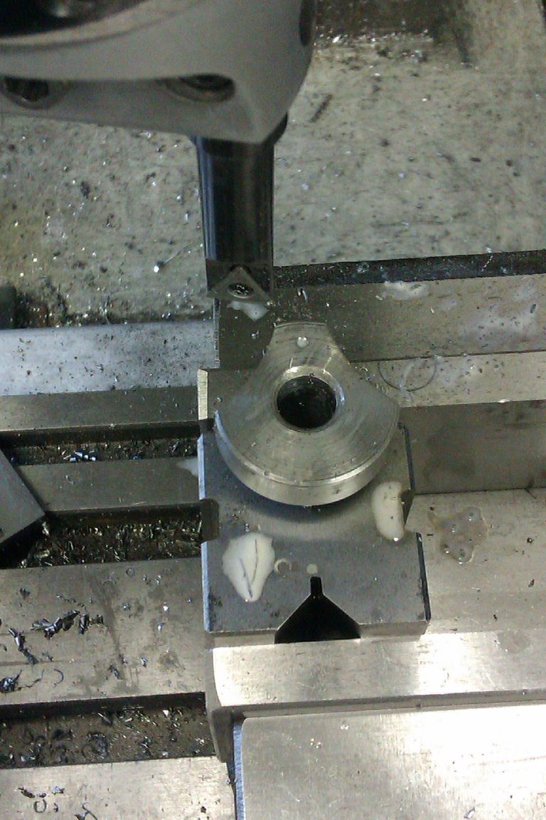
      Thank you for your photo – it give me confidence that this can be done. How did you machine the curved surface on the valve block? (I wasn't sure how to get the final radius exactly correct – maybe a boring tool or an accurate endmill?)

      Hi Michael,

      I agree – the monobloc design is certainly easier – though it is aesthetically pleasing to have a round cylinder. John's design on paddle ducks uses a square cylinder block and a square valve block and it looks good.

      I think if I were building an engine like this full scale I'd start by planning some castings! I don't have the skills or equipment needed to cast metal though. Another option would be to buy castings but I'd like to make something which could be made again in 30 years without having to worry about whether the firm making the castings had gone out of business or changed their designs – hence the decision to use stock even though that would be a very bad way to build a full sized engine.

      I think a bit about a mill engine I remember from when I was young (gone now).

      I should try to explain some of the method in the madness of my design:

      I'm trying to keep the steam path from the valve to the the cylinder as short as possible because both hot incoming and cold exhaust steam will be passing through this path and I'd like to try to minimise transfer of heat between the two. (I don't have the skills to make full Corliss valve gear unfortunately.) I'm also trying to keep the cross sectional area of the steam ways roughly constant until the steam expands into the cylinder where it can expand and do some work.

      Will

      Advert
      #98227
      JasonB
      Moderator
        @jasonb

        The curve was cut with a boring head in the mill, the valve block just proud of one side of the vice. Don't have a picture of the exact process but this will give you an idea. The boring head is set so it swings the right radius and then the work advanced into the tool until the curve is of the right depth.

        Firefly147


        Personally I would us estick solder not the paste.

        J

        Edited By JasonB on 12/09/2012 07:29:05

        #98231
        MICHAEL WILLIAMS
        Participant
          @michaelwilliams41215

          null post


          Edited By MICHAEL WILLIAMS on 12/09/2012 09:52:08

          #98232
          Clive Hartland
          Participant
            @clivehartland94829

            Will, with enough heat you should be able to silver solder the combination without leaving blobs, if you get blobs you are applying the stick too early and melting the stick in the flame.

            The job should be hot enough to melt the stick ,and if you have applied the flux properly the silver solder will immediately fill the join.

            I am with Jason on the solder, use a stick and forget the paste. Paste is used for induction brazing where items are heated in an induction oven and the paste then is gap filling. Not for flame soldering.

            If you plan your maching so that you get a 'Procedure' of work done instead of a hap hazard system then you will find that the work will proceed steadily and accurately. Plan it all ahead and see how it works out.

            My next project is a jig to hold the Planer blades so that I can sharpen them on the Worden tool and cutter grinder. I can achieve the 30deg angle in the jig so i only need to clamp it to the table.

            Clive

            #98245
            Ian S C
            Participant
              @iansc

              The first place I use Loctite liquid gasket was on the joint of the two halves of a little Villiers 2 stroke, many years ago. When I rebuilt the wee motor, I was too lazy too remake the thin paper gasket. On later jobs I'v found it easy to disasseble part assembled with the liquid gasket. Ian S C

              #98249
              MICHAEL WILLIAMS
              Participant
                @michaelwilliams41215

                Hi Will ,

                I should try to explain some of the method in the madness of my design:

                I'm trying to keep the steam path from the valve to the the cylinder as short as possible because both hot incoming and cold exhaust steam will be passing through this path and I'd like to try to minimise transfer of heat between the two. (I don't have the skills to make full Corliss valve gear unfortunately.) I'm also trying to keep the cross sectional area of the steam ways roughly constant until the steam expands into the cylinder where it can expand and do some work.

                Given your previously stated working pressure and size of engine the maximum cylinder efficiency that you can achieve in an 'ideal' engine is about 4 % and in a real engine only about about 2 % . It doesn't matter whether you adopt a very complex engine design or a very simple one – the efficiencies for the different designs are going to be about the same .

                The temperature of the in going steam is about 120 deg C and the exiting steam about 110 deg C – almost the same really and any differential heat loss will be swamped by more general losses .

                Regards ,

                Michael Williams

                #98261
                Will Robertson
                Participant
                  @willrobertson16447

                  Hi Jason,

                  Thanks for the advice. I'll have a look around and see if I can buy a suitable tool at an affordable price. If not, I can maybe make a simple one.

                  Hi Clive,

                  I'll see how I get on with the silver solder. I've never soldered anything this sise before so I'm only guessing how it will turn out. (I always had a reputation for good soldering but this was on a much smaller scale!)

                  Yes – I'm definitely trying to plan every step of the machining in detail – the last thing I want to do is make a mistake which wrecks hours of work.

                  Hope the jig goes well – post some photos!

                  Hi Ian,

                  Thank you very much – that gives me a lot of confidence to go ahead with using a liquid gasket.

                  Hi Michael,

                  Thanks for the expected efficiency figures. Yes – exactly right – with 120 C saturated steam most of what I'm thinking about (including piston valves) is completely pointless. If I can get the model to run well I'd like to get a proper boiler for it so that I can see how well it works with superheated steam at higher pressure. Even with superheated steam and high pressures you are right that these points will probably be academic in a small model. (Thought the Stuart Sirius apparently achieved impressive efficiency.)

                  The subject of saturated steam raises another point – should I fit small drain valves to the cylinder? There's likely to be a lot of condensation when the engine is warming up, the piston valve might trap that condensation in the cylinder – especially if I have to fiddle about to get the valve timing right – and that could damage the whole model.

                  Will

                  #98280
                  JasonB
                  Moderator
                    @jasonb

                    Will here is a simple way to make a cutter, the last third photo shows it being used on a crank web just like mine. Takes a bit more time to set the dia but will do the job.

                    J

                    #98432
                    Sub Mandrel
                    Participant
                      @submandrel

                      Hi Will,

                      A slide valve can lift off its seat, piston valves can't, so drain cocks are a very good idea for piston valve engines.

                      Neil

                      #98444
                      Will Robertson
                      Participant
                        @willrobertson16447

                        Hi Jason,

                        Many thanks. I'll start thinking about building one – got a big chunk of scrap steel that might do the job nicely

                        Hi Neil,

                        Many thanks! Drain cocks will be fitted ( or I suppose in this age of political correctnes I'd better call them 'drain valves' ). I've heard horror stories from refrigeration engineers about what can happen when a trace of condensate finds its way into a compressor so best to avoid the risk of this happening to my engine.

                        When reaming in model engine building, are straight flute machine reamers or spiral flute machine reamers best?

                        Will

                        Edited By Will Robertson on 15/09/2012 22:36:38

                        #98942
                        Will Robertson
                        Participant
                          @willrobertson16447

                          Hi all,

                          A bit of a pause here while I wait for tools to make their way through Swiss customs and enjoy a holiday.

                          One thing that's been troubling me for a long time – a lot of the questions I've asked on here seem fairly basic and I feel bad about taking up people's time asking them. I bought a heap of books on building model steam engines but the overall quality of the information in the books was so poor that eventually I gave up and decided that I was better spending time, money and space on tools rather than more books. Can anyone recommend any good books on building model steam engines that give sound theoretical and practical advice from an engineering perspective?

                          Will

                          #99016
                          Clive Hartland
                          Participant
                            @clivehartland94829

                            Will, as no one answered your query about Reamers I will try to cover it. The straight flute reamers are generally hand reamers and suited to assembly of parts where holes need aligning and one part is interferance fit and the other a push fit. Like locating pins to ensure that an item is assembled in the right position. Also through reaming bushes etc.

                            Spiral flute reamers are used mainly on machines and are good for holes that have keyways and lands as the spiral will ride over them.

                            Also for through holes, but should not be used for blind holes.This because the swarf is pushed forwards and fills the blind hole in front of the reamer. For this application a straight flute reamer is OK.

                            All reamers should be used at slow speed though I understand that Carbide reamers can be used at high speed. Lubrication is essential to clear swarf from the lands, also clearing the reamer occasionally.

                            cant help with the books but I am sure someone will see your request and come up with an answer.

                            Are we going to see some metal being cut soon?

                            Clive

                            #99069
                            Will Robertson
                            Participant
                              @willrobertson16447

                              Hi Clive,

                              I've come to a bit of a sticking point with the restoration of the Stuart S50. The flywheel is attached to the drive shaft and needs to come off but I don't know how. I think the flywheel is normally attached to the drive shaft using one or (better) two grub screws but the individual who attacked this engine hasn't used grub screws – I've no idea what he's done – I suspect drifting or glue but I'm not sure. Plan at the moment is to support the flywheel on some wood then wallop the drive-shaft with a small steel hammer. If that fails I'll use successively bigger hammers. I'm a bit worried thought that i might shatter the cast iron flywheel.

                              The holes at the back and at the front of the steam chest are out of alignment – I'll try and get some long series drills and correct that.

                              Plan for the S50 cylinder is to attempt to mount it in a 3 jaw chuck, if that fails then a 4 jaw chuck. Will protect the casting from being marked by the jaws by using foil from an aluminium drinks can. I'll then re-bore the cylinder using the Ifanger ECS boring tool. The lathe doesn't state speeds so I'll just set the workpiece to rotate fairly fast and the tool to move as slowly as possible and take lots of light cuts with no cutting oil or coolant. The long Ifanger tool is a few mm shorter than the cylinder so I think I'll deal with that by mounting the tool at a slight angle.

                              Will

                              #99072
                              JasonB
                              Moderator
                                @jasonb

                                If you must use a steel hammer then put a bit of brass, copper or aluminium between it and the crankshaft, hitting with a hammer will raise a burr and you won't get the flywheel over that.

                                Is the flywheel painted? if so there could be some filler hiding a grub screw hole

                                Support the flywheel on a bit of tube that bears on the hub, don't rest the rim on teh vice jaws as that will put unwanted load on the spokes

                                Use the 4-jaw to hold the cylinder and clock it to run true with a DTI

                                J

                                #99074
                                Will Robertson
                                Participant
                                  @willrobertson16447

                                  Hi Jason,

                                  Yes – the flywheel is painted – only primer then one surface coat – not the more meticulous painting that better models have – I ckecked for any evidence of a change in the texture of the surface that could indicate some filler underneath but there wasn't any and filler hasn't been used anywhere else on the engine.

                                  What sort of wobble should I aim to get on the DTI when I've got something reasonably true? (I know that in theory I should aim for zero deflection on the DTI but I'm not sure what to aim for in practice.)

                                  Will

                                  #99080
                                  Michael Gilligan
                                  Participant
                                    @michaelgilligan61133
                                    Posted by Will Robertson on 11/09/2012 22:43:42:

                                    Thank you for your advice re. silver solder. I saw some paste silver solder and thought that it would be ideal for soldering the valve gear to the cylinder. When I saw the price (100 francs) I had to reconsider. Can anyone recommend a good place to buy this in smaller quantities at a more affordable price? (My memory from electronics was that paste solder always had a 'best-before' date so it was best to buy little and often rather than keeping a large stock for a long time.) For aesthetic reasons I'm trying to avoid bobby solder marks around where the cylinder and valve gear join which I think I might get if I use silver solder wire and flux.

                                    Will


                                    Forgive me for jumping-in late; but I don't think anyone has yet mentioned the use of Silver Solder in the form of Pallions [which translates as Butterfly Scales].

                                    These are tiny squares, cut from Silver Solder strip … a technique widely used by Jewellers.

                                    Depending upon the detail of the assembly; these can be applied between the faces of the joint [if gravity, or pressure, can be applied to "settle" it], or around the edges [where we rely entirely upon capilliary flow] … The trick, as always, being to use the minimum quantity of Solder to precisely fill the joint.

                                    MichaelG.


                                    Pallions are illustrated about 1/3 down this page.

                                    Edited By Michael Gilligan on 22/09/2012 15:25:29

                                    #99081
                                    MICHAEL WILLIAMS
                                    Participant
                                      @michaelwilliams41215

                                      Hi Will ,

                                      Ideally you want to line up on the original bore ???

                                      If so put a piece of true bar in the hole with a long piece sticking out and clock true on that in two places . Running true is running true – certainly less than +/- one thou even on improvised work like this .

                                      Drilling through pairs of misaligned holes just makes them worse – you need to put new metal in one or other and drill fresh .

                                      On your earlier query regarding books – the only good one relating to model size steam engines that I know of was written nearly a hundred years ago by Greenly . Personally I gave up wasting scarce pocket money on disappointing books written by ' expert model engineers ' when I was 12 .

                                      If you really want to understand steam technology seek out books relating to full size practice .

                                      If you have specific queries about how steam engines work just ask me anytime .

                                      Regards ,

                                      Michael Williams .

                                      Edited By MICHAEL WILLIAMS on 22/09/2012 15:32:32

                                      #99109
                                      Clive Hartland
                                      Participant
                                        @clivehartland94829

                                        Will, you can extend the Ifanger tool in the holder a little bit, at times I have only had 15 to 20 mm in the holder.

                                        True, angling the tool a little will allow the holder to go further into the bore but check by going through with out touching with the machine switched off first, you can sometimes hit the back of the holder against the far side of the job.

                                        Clive, PS, took another 30lb of honey today with possibly another 60lb but the weather will decide if I can.

                                        #99128
                                        Will Robertson
                                        Participant
                                          @willrobertson16447

                                          Hi Michael Gilligan

                                          Thank you for your advice about Pallions – this seems a great way to get exactly the right amount of silver solder exactly where it's needed

                                          Hi Michael Williams,

                                          Thanks – I'll aim for better than one thou (0.025mm in my metric speak).

                                          Thanks for your comments re. books. It looks like you've had exactly the same experience as me. Good to know that at least I'm not alone in this.

                                          I don't have Greenly – will buy it ASAP.

                                          >If you really want to understand steam technology seek out books relating to full size practice .

                                          I think you're right – do you have any recommendations?

                                          >If you have specific queries about how steam engines work just ask me anytime .

                                          There's one slightly involved one… Initially I'll operate the valve direct from an eccentric – I'd like to leave my options open though so that if I have time in future I can adjust for maximum torque or maximum economy – I reckon that would be achieved using Walschaerts valve gear or similar but I can't find any detailed theoretical or practical advice on using this kind of valve gear in models. (I think I can maybe model it by adding two sine waves of equal frequency and adjustable amplitude but I don't know what the difference in phase between the two should be.)

                                          Hi Clive,

                                          I forgot to say the other day – thank you for your help and clarification on machine reamers – that's helped me to understand them a lot better – I think in future I'll go for the spiral fluted ones.

                                          Good to hear about the honey – having a few problem with an entirely different sort of insect here at the moment – the mosquitos are out much later than usual…

                                          Sadly, it looks like the S50 may be nearing the end of the line. It looks like when I do the re-boring necessary to repair the bore and take out a flaw in the casting I'll break through into the steamways. Maybe I should ask Stuart if they'll replace the casting – the flaw seems to be a bubble c. 1mm diameter in the cast iron.

                                          I could make a cylinder lining but I've never done this before and I don't have access to liquid nitrogen to fit it.

                                          Will

                                          #99129
                                          Will Robertson
                                          Participant
                                            @willrobertson16447

                                            PS – Sorry – Should I go for the 1979 or 1954 edition of Greenlays?

                                            #99130
                                            Clive Hartland
                                            Participant
                                              @clivehartland94829

                                              I dont think you need Liquid Nitrogen for a liner for the S50 Will. Bore it through and then make a liner and allow about 0.01 or less then, heat up the casting and freeze the liner in the freezer and then force it home. Just take the chance, as I have done this with big bearings.

                                              Clive

                                              #99146
                                              JasonB
                                              Moderator
                                                @jasonb

                                                For something as small as the S50 you could even loctite the liner into place with one of the higher temp locktites like 648. I also doubt that a 1mm blow hole will make any difference to performance, you could always fill with JB weld just before taking the last 0.1mm off.

                                                J

                                                #99170
                                                Will Robertson
                                                Participant
                                                  @willrobertson16447

                                                  Hi Clive,

                                                  I think you're right. I've seen heat alone used to fit parts when rebuilding gear boxes. Maybe the bigger temperature difference given by liquid nitrogen in needed in fitting cylinder linings for industrial and automotive internal combustion engines but not in something like an S50 where the pressures involved are much lower.

                                                  Hi Jason,

                                                  I didn't know about JB Weld. I think I'll give it a try then if it fails I'll try the cylinder lining. There are a lot of scratches and gouges on the cylinder so hopefully I can cover the whole of the inside of the cylinder in JB Weld then re-bore it. (The individual who attempted to machine the castings before I bought the engine on Ebay made a complete mess of most of the machining.)

                                                  I'm planning to make the piston 0.1 mm diameter less than the cylinder. The idea is to make the piston in two halves with a Viton o-ring and outside that a Teflon split o-ring so that the Viton o-ring presses against the Teflon o-ring to give a good seal while the Teflon to metal (or JB Weld) interface will give good wear resistance. Should that work OK?

                                                  Will

                                                  #99184
                                                  JasonB
                                                  Moderator
                                                    @jasonb

                                                    I would not use the JB weld like you say, best to just fill the hole and then take a light skim off the whole bore to remove the scratches, the JB weld will not stay in place in shallow scratches.

                                                    Its usual to allow some sideways movement of "O" rings not squash them to a tight fit my applying pressure.

                                                    Also if you are going to use O rings then you really want to also lap teh bore as a macwill be too rough and will wear away the ring very quickly.

                                                    J

                                                    #99188
                                                    MICHAEL WILLIAMS
                                                    Participant
                                                      @michaelwilliams41215

                                                      Hi Will ,

                                                      It depends on where it is but a blowhole in a cylinder casting which is away from ports or anything critical can be repaired by drilling through form the outside of the cylinder to clear the bad metal and then inserting a same metal pin . Pin can be press fit or threaded . With brass cylinders and low pressures can sometimes even be soft soldered .

                                                      If using a liner remember that it can't go anywhere because of the end covers – make it a transition fit and dead length and push it in . Smear of sealant if you like . Cut away any bits needed for ports .

                                                      Before doing anything at all about boring out and fitting liners however it may pay to make a proper assessment of the problem as it stands now – what exactly is wrong with the existing bore ???

                                                      One very good and relatively low cost book that you might like to read is :

                                                      Advanced Steam Locomotive Development – Three Technical Papers . Author L.D.Porta

                                                      Camden – ISBN 978-0-9547131-5-7

                                                      I'm writing out some notes about your valve gear question and will post these later .

                                                      As Jason says O rings need sideways clearance . About 1.5 times ring diameter is a good starting point for width of groove . All you need for this little engine is just the O ring itself . Make the radial nip quite light – you should be able to pull the piston back and forth easily by hand .

                                                      Regardless of what actual sealing method is used the piston needs to be a nice close fit in the bore . Often described differential expansion problem is minute in tiny engines running on the usual tepid fog . Make piston a nice fit and only if it proves nescessary ease the diameter a little after test running .

                                                      Regards ,

                                                      Michael Williams .

                                                      Edited By MICHAEL WILLIAMS on 23/09/2012 12:47:10

                                                    Viewing 25 posts - 126 through 150 (of 286 total)
                                                    • Please log in to reply to this topic. Registering is free and easy using the links on the menu at the top of this page.

                                                    Advert

                                                    Latest Replies

                                                    Home Forums Beginners questions Topics

                                                    Viewing 25 topics - 1 through 25 (of 25 total)
                                                    Viewing 25 topics - 1 through 25 (of 25 total)

                                                    View full reply list.

                                                    Advert

                                                    Newsletter Sign-up