Cylinder Boring Techniques for Steam Engines

Advert

Cylinder Boring Techniques for Steam Engines

Home Forums Beginners questions Cylinder Boring Techniques for Steam Engines

Viewing 25 posts - 251 through 275 (of 286 total)
  • Author
    Posts
  • #109778
    Will Robertson
    Participant
      @willrobertson16447

      I found some advice on hard bonded and soft bonded diamond blades here

      **LINK**

      – I'm not sure how well this applies to diamond grinding wheels but I think it seems to imply that for finishing something hard like a lathe tool I should use a soft bonded diamond grinding wheel – I could be wrong though – fingers crossed…

      I haven't got anywhere with finding out what "Steel 50" and "Steel 51" mean – think I'll just need to give them a try and find out what happens – any suggestions welcome!

      Advert
      #110417
      Will Robertson
      Participant
        @willrobertson16447

        What's the maximum temperature of superheated steam that would normally be used in a model stationary engine?

        I've been trying to make a final selection of metals for my engine. I'd like to quickly check coefficients of thermal expansion to make sure that the main cylinder and piston valves don't cease when it heats up (I think I'm OK but I'd like to do some quick calculations to check). What is the maximum temperature of superheat that model engineers normally use? (I know that initially I'll be using 120 C warm fog but I'd like to design the engine so that it is hopefully capable of running on superheated steam in the future.)

        I reckon that the thermal expansion might be smaller then my machining tolerances but I'd like to check and make sure.

        #110457
        Will Robertson
        Participant
          @willrobertson16447

          I think I found an answer from a lubricating oil manufacturer – they state "Light Super Heat
          550 Farenheit" 550 Farenheit = 288 Cenigrade so that should give me an idea of the kind of temperatures involved. 288 Cenigrade seems like a high temperature to use in a model so please let me know if I'm wrong.

          #110461
          JasonB
          Moderator
            @jasonb

            Sounds about right as Model Engineers Handbook says 500F could typically be found on a 5" loco.and goes on to give tables for upto 700F so base your calcs on say 300C and you should be fine.

            #110463
            Ian S C
            Participant
              @iansc

              If you use a cast iron cylinder, piston set.. no problem, if the mix is bronze cylinder, and cast iron piston, no problem, except that as they get hotter, the gap will increase a fraction, greater coefficient of expansion for bronze. Ian S C

              #110535
              Will Robertson
              Participant
                @willrobertson16447

                Thanks very much. I have to admit that when I started out I didn't realise that model engineers used so much superheat – all adds too my respect to folk like Greenly and their small and amazingly powerful engines. I'll see how the thermal expansion works out – was thinking about using bronze and steel for the piston valves – I'll play around with the numbers and give it some thought.

                #110544
                Ian S C
                Participant
                  @iansc

                  Teflon is a material some times used in piston valves, just a thought. Ian S C

                  #110642
                  Will Robertson
                  Participant
                    @willrobertson16447

                    Hi Ian,

                    Thank you very mcuh. I had thougth about the possibility of Teflon o-rings on the piston valves but your idea of making the vlaves out of teflon is very interresting – in many ways it's ieal – easy to machine, heat resistant (some manufacturers say to 260 C others say to 300 C – melts at 330), low friction, predictable thermal expansion, lightweight so can be purchased without large shipping costs. A metal shaft could be made with a Teflon valve spool mounted to it.

                    Perhaps a filled PTFE (filled Teflon) material could be used – I've heard about copper filled PTFE being used in hydraulics but I've no experience with any filled PTFE material.

                    Will

                    #110778
                    Will Robertson
                    Participant
                      @willrobertson16447

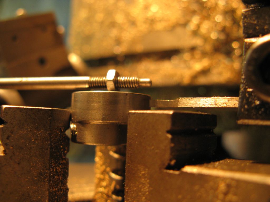
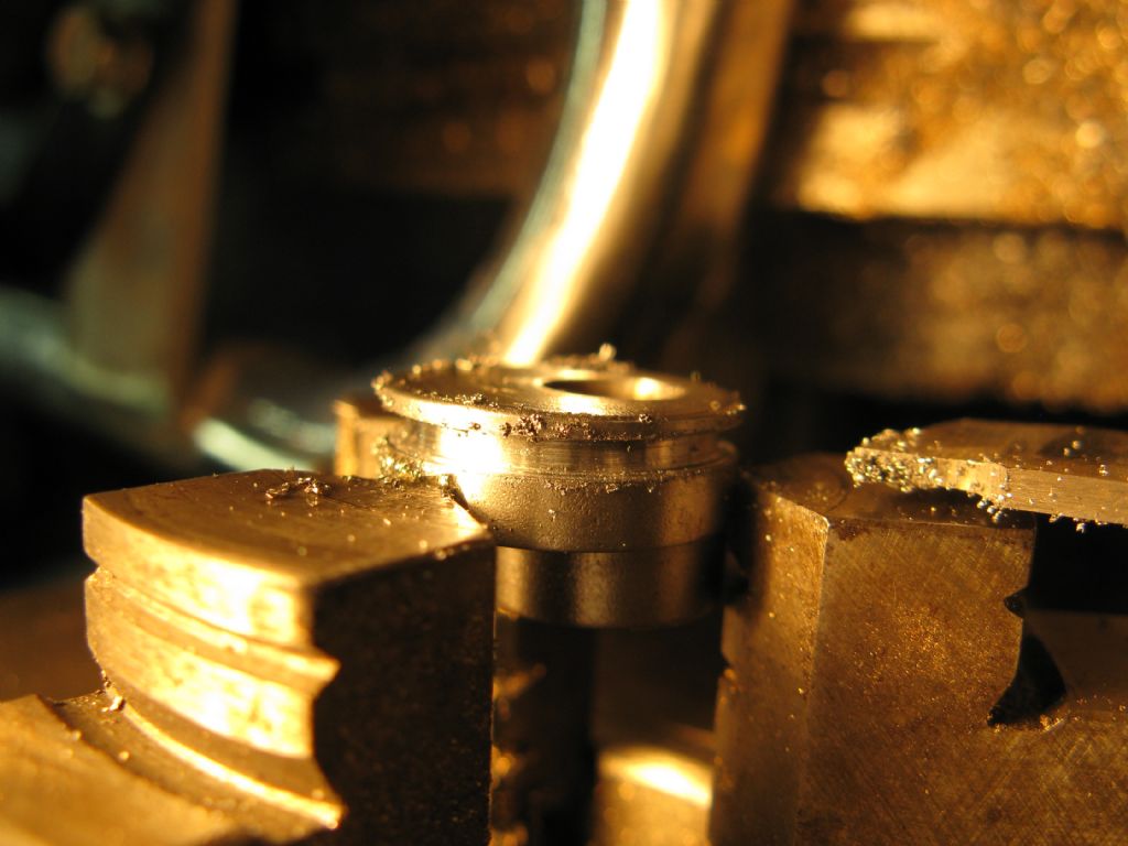
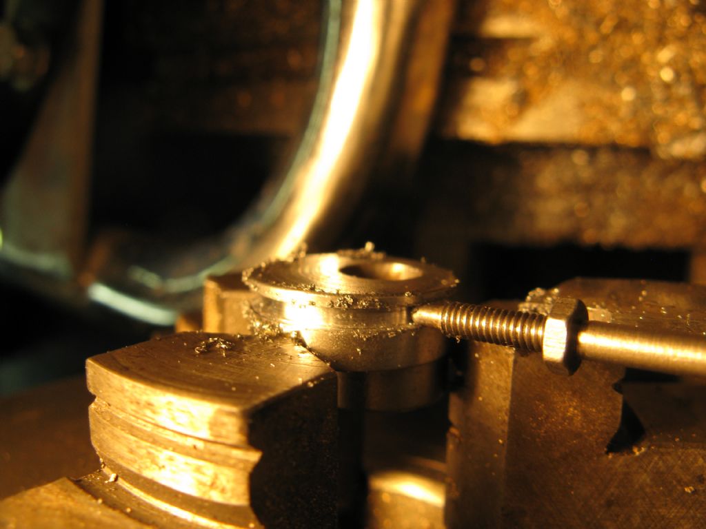
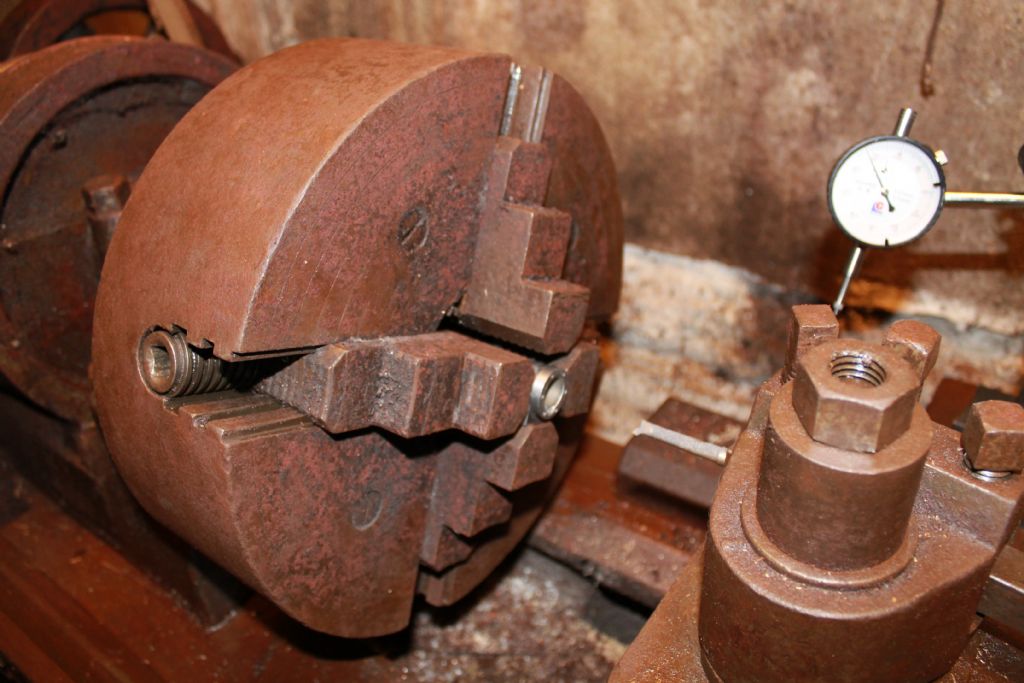
                      Some pictures of the restoration of the knackered S50 (a la Ebay) as promised. The grove on the eccentric was missing which allowed the eccentric strap to slip sideways, ceasing the engine. Aligning the eccentric so that it was true was a bit tricky – even in the small 3 jaw. Very little space so cutting close to the chuck. Here's the smallest lathe and a modified parting off tool being used to cut the grove.

                      Preparing to cut missing eccentric grove.

                      Not much clearance...

                      Perfect running fit.


                      Edited By Will Robertson on 02/02/2013 23:29:31

                      #110789
                      Ian S C
                      Participant
                        @iansc

                        A groove on the eccentric looks more like it than the S6 that has a ridge on the eccentric, and the groove in the eccentric strap, but as it happened I had a boring tool exactly right to do the job. I quite liked the restoration job, quite used to that sort of work in 12" to the ft scale.

                        Teflon rings, if you are like me, I pull things to bits to get at useful stuff, car shock absorbers; there is a piston inside 25 35 mm dia, this these days normally has a plastic/ ? teflon ring on it, the older ones had an iron ring. For piston valves, the two heads of the valve is formed in the examples I have seen, are made up of a number of Teflon washers, say 1 mm thick, and held in place by metal washers under the end nuts.

                        I use Carbon impregnated Teflon for bushings in my Stirling Engines, when I bought my bit of 25 mm dia rod about 20yrs ago it cost around $NZ 2 per inch, I got 12", don't know how much it is today. A lot of the bushes I made were machined on the lathe, and I kept all the swafe, there is a sketch in my gallery of a mold for forming teflon bushes. Use Teflon tape in the steam glands. Ian S C

                        #110869
                        Will Robertson
                        Participant
                          @willrobertson16447

                          Hi Ian,

                          I'm like you – I don't believe in the 'throwaway society' – broken equipment gets taken apart and repaired or used for parts. I'll keep my eye open for some old shocks.

                          Using a number of Teflon washers might have an advantage over a solid piece of Teflon. I need to learn more about the theory of this and the principles behind an effective seal.

                          Interested that you used carbon loaded Teflon for bushes for Stirling Engines – self-lubricating. I'm always impressed by people who can make Stirling engines – I'll maybe try some day but I'm not ready for it yet.

                          Interesting to see some of your photos – do you work with aero-engines as well?

                          Will

                          #110872
                          Will Robertson
                          Participant
                            @willrobertson16447

                            Have been going through the catalogue of a local metals supplier trying to translate and finalise what metals to use for the engine. What are people's thoughts on the following?:

                            For the piston, piston rod, etc.: 1.4305 Stainless Steel
                            – I think this what we call 303 steel (chosen because of its good machining properties and corrosion resistance)

                            For the cylinder Rotguss GC-Rg 7
                            – I think this is what we call gun metal (chosen because of its good properties as a bearing surface and good machining properties)

                            In general, the bearing surfaces will be formed by steel and Rg 7.

                            Other parts to be made out of the above if critical, otherwise random scrap.

                            I could make things easier by taking advantage of the very good machining properties of brass but I've been warned that it's a poorer bearing surface than bronzes so I'll use gunmetal.

                            Here are to coefficients of thermal expansion:

                            1.4305 Stainless Steel
                            20-100 C 16.0
                            20-200 C 17.0

                            Rg7 18,5

                            So if parts made of Rg 7 and 1.4305 Stainless and each 20mm in length were heated by 200 C the part made of Rg 7 would end up .03 mm larger – guessing that this shouldn't be a problem.

                            In future I'd maybe like to make an all-cast-iron engine but I think it will be interesting to make this first engine from steel and bronze.

                            #110878
                            Clive Hartland
                            Participant
                              @clivehartland94829

                              Will, first thing , you do not need to make it like a watch. If you do it will not work. Just make the parts to size and go for it and dont over emphasize on the expansion ratios of the different materiels. The model should be fairly slack and easy to rotate and the piston freely move in the bore.

                              Just make it accurately and to the drawing and you will succeed.

                              Clive

                              #110923
                              Ian S C
                              Participant
                                @iansc

                                Will, used to work on aeroengines, did my apprenticeship on Continental engines mainly, most of them O-470/ IO-470, and IO 540, on Cessna 185, and 188 Agwagons, Did some airframe work too. That was quite a while ago, but aeroplanes are a disease, and they never go way. Ian S C

                                #110976
                                Will Robertson
                                Participant
                                  @willrobertson16447

                                  Hi Clive,

                                  Thanks – I'll keep it fairly slack.

                                  Hi Ian,

                                  That's interesting. I'm drawn aero engines because once you learn to maintain an aircraft there's a fairly good chance it'll be in the air a long way into the future. With cars the whole lot gets scrapped every 15 to 20 years, your knowledge goes with it and you end up having to buy a newer one, re-train and buy a bigger computer to plug it into when it goes wrong so that you can give yourself a headache trying to understand a new set of cryptic error codes.

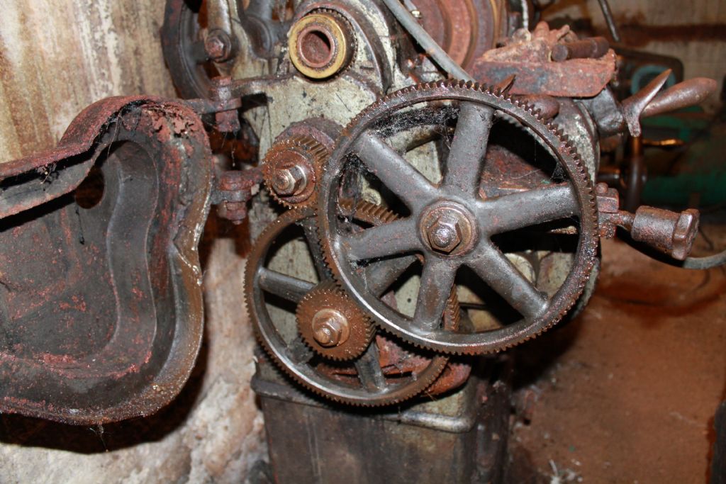
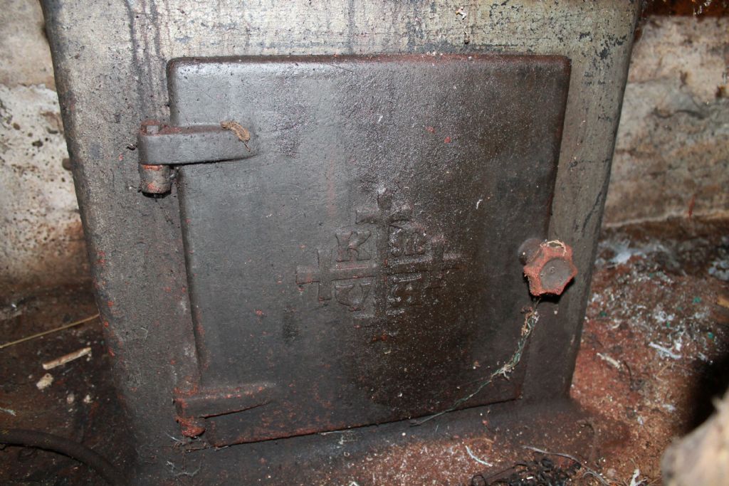
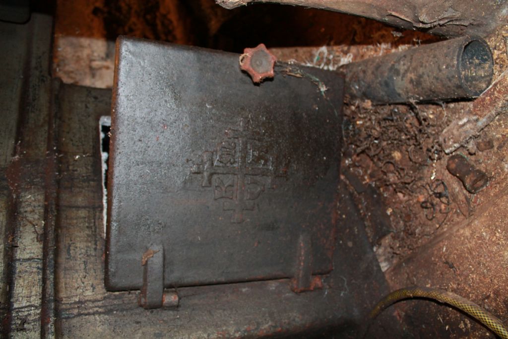
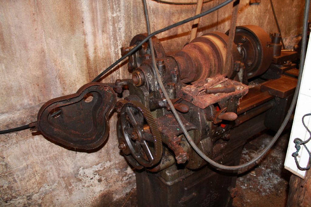
                                  The last set of photos were a bit boring – these are a bit more interesting. Just in case anyone didn't believe me about the age of the wonderful lathe or the temperatures involved…

                                  Gear chain - largest gear ratio possible - too large to fit in the gear box...

                                  The biggest gear ratio possible for the leadscrew on this lathe. The gear chain is so large that the door won't close.

                                  Can anyone identlfy this maker?

                                  Can anyone identlfy this maker?

                                  Can anyone identify the maker?

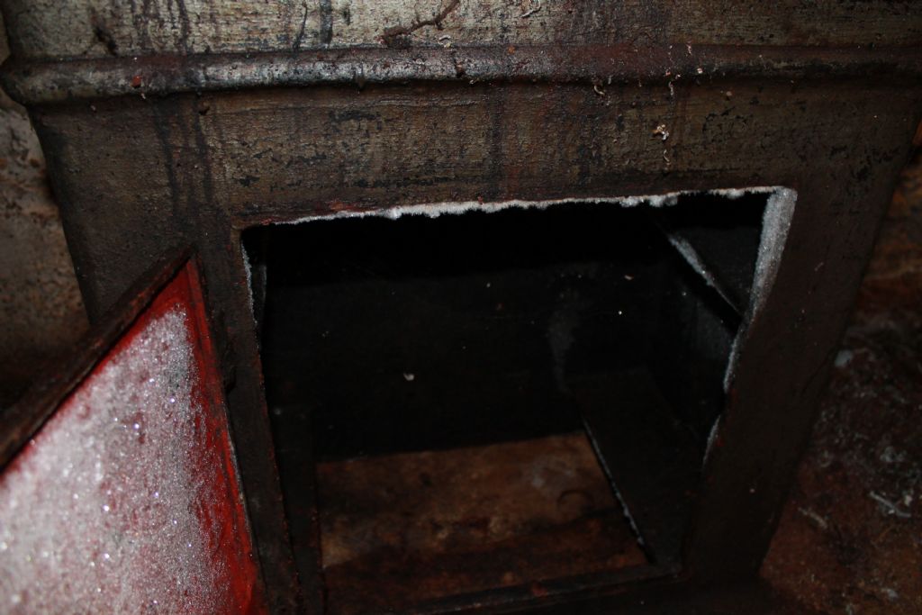
                                  Frost in the lathe, - 8 C in the workshop during boring.

                                  Frost inside the lathe – the boring was done in Arctic Norway with the unheated farm workshop at about minus 8 Centigrade.

                                  Wonderful technology.

                                  Over 60 years and still going strong

                                  Just a moment to pass the mandatory health and safety inspection with flying colours. (Note the moving drive belts from the overhead drive shaft and the positioning of the 3 phase electrical cables.)

                                  Ready to cut.

                                  Ready to bore. The Ifanger ECS boring bar is in use (thanks Clive!). (4 jaw is centred and the DTI is just hitching a ride in this photo.)

                                  Will

                                  Edited By Will Robertson on 04/02/2013 21:21:03

                                  #111014
                                  Ian S C
                                  Participant
                                    @iansc

                                    Correcting mistake: Continental IO520 engine, not 540, don't know where that came from, maybe Lycoming. Ian S C PS; With the number of hours done by some aircraft engines, theres proberbly some still flying that I worked on. Ian S C

                                    #111402
                                    Will Robertson
                                    Participant
                                      @willrobertson16447

                                      Hi Ian,

                                      I know from a friend who flew a lot in the USA that light aircraft often stay in the air a very long time – way beyond their design lives – guessing that it's he same here and that many of yours will still be in the air.

                                      Can anyone guess at the maker of the lathe in Norway? I've never been able to recognise the logo on the door and I've nothing else to go on.

                                      Will

                                      #111586
                                      Will Robertson
                                      Participant
                                        @willrobertson16447

                                        Things aren't going so well here – the F600 and F1200 carbide grit arrived for finishing the cylinder bore of the S50. I'd assumed that F600 was roughly equivalent to P600 but it seemed very fine when it arrived – found a conversion chart and it turns out that F600 actually seems to be equivalent to about P2000.

                                        **LINK**

                                        Looks like I'll need to buy some coarser grit – I think F240 or F260 would be roughly equivalent to P600.

                                        Does anyone have any advice?

                                        Will

                                        #111605
                                        MICHAEL WILLIAMS
                                        Participant
                                          @michaelwilliams41215

                                          Hi Will ,

                                          (1) I've got a bit more time to spare and for various reasons I'm (slightly) less grumpy than usual so if you are amenable I'll start helping you along with your project again .

                                          (2) For starters you can ask me any direct questions and I will answer them .

                                          (3) You need to get a working piston and cylinder assembly a soon as possible just to get the ' feel ' of your engine – its much easier to do further design with a few made parts in your hand .

                                          (4) In an engine of the size that you are building and with a bronze cylinder there is no need to do any lapping of the bore . I suggest that you use a plain bored hole using topslide set exactly parallel and tiny cuts with very sharp but rounded end tool .

                                          You can if you wish use an old trick and ' null ream' the bore – bore hole out until lead of reamer will go in almost all the way and just stop at the parallel section – this leaves at most half of one thou to remove with further traverse of the reamer and a perfect reamed bore will result . Bit of oil as well .

                                          Sharp reamers only become unstable and produce chattered and out of round bores if they are either run too fast or given too much metal to remove . Corollary is that if reamer is given almost nothing to remove and is run at slow speed a perfect bore results .

                                          In other applications I have sometimes bored a hole as described and then finish reamed by hand off the machine .

                                          Personally the plain bored cylinder would be what I would choose but I'd hedge my bets by making it reaming size as well just in case a microscopic clean up is needed .

                                          Regards ,

                                          Michael Williams .

                                          #111873
                                          Will Robertson
                                          Participant
                                            @willrobertson16447

                                            Hi Michael,

                                            Thank you. I'm gradually learning that with a good lathe, good stock, simple tools and some knowledge I can achieve very good surface finishes. It's very rewarding. (Especially after previous setbacks using poor quality steel stock.)

                                            I'll push forward with ordering the stock for the piston and cylinder – I think once that's done it'll give me more confidence. Thanks for pushing me on.

                                            I'll be delayed a bit waiting for parts to come through (the circular saw I use hasn't had a new blade in years and is completely blunt so I've got to wait for a new blade for that – 1 week delivery time, also 3 week delivery time on stock).

                                            >Sharp reamers only become unstable and produce chattered and out of round bores if they are either run too fast or given too much metal to remove

                                            Thank you. I've read so much about reamers that's confused me. I'll plan the machining and let you know how much I plan to leave for the reamer so that I make sure I get it right.

                                            Is there any good web page giving the speed of rotation and depth of material to leave for the reamer for reaming different materials? Is there any rule of thumb to know whether to feed a reamer "snow and steady" or to "woodpecker" it?

                                            I'll check my reamers to see if I can use your 'null ream' trick.

                                            >with very sharp but rounded end tool .

                                            Thanks – I made one of those last week and tested it turning – have come to the conclusion that it's good to test a boring tool turning some scrap to see what sort of surface finish it gives before using it for boring – I'll post a photo so that you can have a look at it and make sure it's OK

                                            One quick specific question:

                                            I make my HSS lathe Tools on a normal garage coarse and fine grinding wheel but I'd like to finish them on a diamond grinding wheel – what grit of diamond wheel should I use and should I use soft-bonded or hard bonded? (I'm guessing about 600 or 800 grit and soft bonded but that's just a guess.) (At the moment I use an inexpensive set of diamond stones to finish the HSS tools – a wheel would cost a bit more but be quicker and easier.)

                                            Will

                                            #111950
                                            Ian S C
                                            Participant
                                              @iansc

                                              To finish your HSS tools you don't need a diamond wheel, get a fine oil stone, and use that, or a diamond lap, use these to polish up the cutting edge, and maintain it between grinds. Ian S C

                                              #112300
                                              Will Robertson
                                              Participant
                                                @willrobertson16447

                                                Hi all,

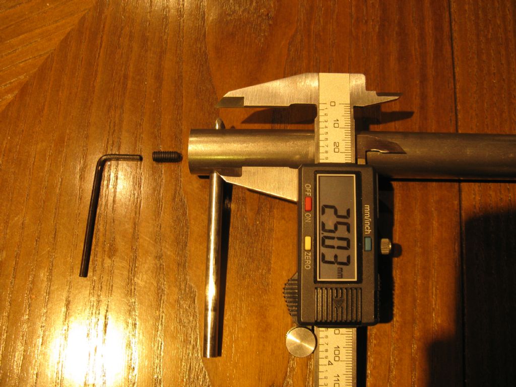
                                                I've built a boring bar designed to cut from about 30mm diameter upwards. This will be used for milling the concave surface on the part that goes between the main cylinder and the valve. The boring bar is made from 22mm diameter steel and is 250mm long with an HSS cutting tool mounted at the end. Is it OK to attempt to mount a boring bar like this in a collet in the milling machine or should it be tapered and fitted direct into the taper of the milling machine? (The largest collet I've got access to is 16 mm but I can see if a bigger one would fit – if not I can turn down the top of the borign tool to fit.

                                                Hi Ian,

                                                I know that a diamond grinding wheel for me must seem both pretentious and decadent. Because shipping costs make up such a large part of the cost of me buying anything and because I tend to buy more from keenly-priced industrial suppliers a diamond grinding wheel actually works out about the same price or cheaper than a decent-sised oil stone or lap. A diamond wheel also opens up the opportunity to hone carbide tipped tools and this might come in handy in the future. It was Hans Rudolf here who first showed me one in action and I was impressed. I'll try and get my paws on both and see how they work out.

                                                Will

                                                #112302
                                                Clive Hartland
                                                Participant
                                                  @clivehartland94829

                                                  The diamond wheels should be used for Carbide tooling, HSS tools only need ordinary wheels and then hone with a stone.

                                                  How are you going to maintain the radius of cut with this boring bar you have made? Have you clamped a piece of HHS bar in it? If you can adjust its position, then fine, mount it straight in the collet by turning the end of the bar to suit the collet dia.

                                                  Clive

                                                  #112490
                                                  Will Robertson
                                                  Participant
                                                    @willrobertson16447

                                                    Hi Clive,

                                                    Here's a photograph of the boring bar. It's intended to be adjusted to sise using a micrometer then the grub screw fixes the HSS tool in position. Clearly, the accuracy of this design is very limited – I've got a more accurate design in mind if I need it.

                                                    I might cut a datum surface on the back to make it easier to set using the micrometer.

                                                    The piece of HSS will be much shorter in use than in the photo.

                                                    Boring Bar

                                                    Will

                                                    #112494
                                                    Clive Hartland
                                                    Participant
                                                      @clivehartland94829

                                                      I think you are over engineering a bit Will, the bar will work fine.

                                                      If you can lay hands on a boring head you can mount your Ifanger Boring tool in it and do just as well.

                                                      I doubt you will need such a long bar for the job.

                                                      Clive

                                                    Viewing 25 posts - 251 through 275 (of 286 total)
                                                    • Please log in to reply to this topic. Registering is free and easy using the links on the menu at the top of this page.

                                                    Advert

                                                    Latest Replies

                                                    Home Forums Beginners questions Topics

                                                    Viewing 25 topics - 1 through 25 (of 25 total)
                                                    Viewing 25 topics - 1 through 25 (of 25 total)

                                                    View full reply list.

                                                    Advert

                                                    Newsletter Sign-up