cutting spur gears on a mill

Advert

cutting spur gears on a mill

Home Forums Workshop Techniques cutting spur gears on a mill

Viewing 25 posts - 151 through 175 (of 439 total)
  • Author
    Posts
  • #563096
    Pete Rimmer
    Participant
      @peterimmer30576
      Posted by brian jones 11 on 15/09/2021 22:27:24:

      Well PR post a pic of a hobbing attachment – not a specialised hobbing machine – that doesnt count, its not for the hobby machinist.

      My point here as I expect you noticed is that we all take for granted that a lathe is generally designed to be able to make screw threads. Its no big deal

      But a mill isnt set up to make gears in a similar way (nor a lathe for that matter)

      In both cases you can go for a dividing head and laboriously rake out each tooth

      I dont know of a simple system that allows you to cut gears with ease and speed (I am discounting the modern use of stepper motors for the job for the purposes of this discussion. No electronics allowable

      You need to lock the spindle rotation with the gear blank rotation by suitable gear chain and the whole should run and chew out a gear – you may need some movement of the cross slide if its a thick blank of course

      Thats hobbing on gas

      So is there a ready made attachment for mill hobbing?

      Hence my pursuit of a cheap charlie way of knock up spur gears – we already know the worm gear method

      and this is an expansion of this method

      Brian I only pointed out your error so that the uninformed don't become the mis-informed, please don't take it personally.

      There isn't a simple solution because it's not a simple process. You don't find ready-made attachments for mill hobbing because the fundamental requirement for hobbing is that the work rotation be timed to the cutter rotation, and your average milling machine doesn't allow for that (there may be some ancient machines that take the table drive from the spindle drive by a geartrain and if you find one of them then you could possibly adjust the gearing to suit).

      Your mention of the worm gear method bears some exploration. Unlike straight spur gears which can be cut with any diameter cutter or hob a worm gear needs to be cut with the same diameter cutter as the mating worm, or else the helix angle is wrong and tooth engagement departs rapidly from ideal. This is very prohibitive for the home engineer as buying custom cutters is very expensive so the most viable options are:

      1. Make a hobbing cutter from hardenable steel that mimics the worm you will make with added clearance. Harden it and grind the cutter teeth sharp. Not a trivial exercise but doable though a lot of work for a single item.

      2. Make a single-tooth cutter to the form and diameter of the worm, tilt it to the helix angle and cut each worm wheel tooth separately. A very laborious task.

      3. Make or modify your design so that a stock thread can be used as the worm and then a stock thread cutting tap can be utilised as a cutter to hob the teeth onto a pre-gashed wheel.

      No3 is often used out of necessity because it can give a good return of effort vs reward in terms of producing a workmanlike result for very little time and effort, The 'wrap-around' nature of the wormwheel teeth allows for a decent flank area for the worm 'cutter' to self-drive the wheel (unlike the spur gear's point contact) and if the material isn't too hard and the work well lubricated can produce very nice results. If the worm is pre-gashed (always recommended) you'll hit your desired tooth count every time.

      The reason why pre-gashing is recommended for free-hobbing is because the pitch of the cutter (or tap, which is a hobbing cutter in this respect) is fixed but the pitch of the teeth on the wormwheel is larger at the OD than at the base circle and only matches the cutter pitch at the pitch diameter. When you start cutting the tips of the cutter will cut the edge of the blank and drive it somewhat however because the hob's pitch which is correct for the pitch diameter but starts cutting on the much larger OD it will naturally try to divide the OD into a greater number of divisions (teeth) than you require. Pre-gashing the work allows you to start your hobbing at a depth that matches the pitch of the cutter more closely to the pitch of the wormwheel at the pitch diameter which has two benefits:

      1. You get the tooth count you want

      2. The cutter will cut more equally both sides.

      You see, by starting your cutting at the outside diameter the distance between each cutting start is 'short' for the tooth spacing at the OD, in order to continue towards full depth the cutter has to continuously shift the tooth profile around the blank away from the driving flank. When your cutting depth gets to the pitch diameter the pitch on the cutter is now correct for the cutting diameter and it will naturally cut the correct number of teeth. As you pass pitch diameter and approach full depth the pitch of the cutter is now 'long' for the diameter at the cutter tip which is why you get under-cut on small tooth count gears (not that you're going to get under-cut at 30 degrees pressure angle).

      So, if you can gash the blank to at least the depth of the pitch diameter you stand a much better chance of getting a good result from your free-hobbing exercise in terms of correct tooth cound AND quality of cut because the load on the cutter and on the driving flank are greatly reduced.

      So you see, worm-wheel fre-hobbing is borne of necessity but free-hobbing spur gears is not because there is no real requirement to. As you have demonstrated, it is actually possible but the result (subject to personal opinion) most often fall far short of what constitutes an even moderately well-made gear.

      This is my personal take on the matter. Feel free to disseminate, disagree or criticise my thinking I will not be offended.

      Pete.

      Advert
      #563099
      brian jones 11
      Participant
        @brianjones11

        Well guys its all good input and shows we are addressing a serious issue – making spur gears

        For this discussion I discount CNC and stepper motor drives as this is a different diocese IMHO

        I also discount the lathe chivving method cos its not on msg and you can make up some complex jiggery to hack away – you cant buy one off the shelf btw

        Ialso discount geared hobbers – the tools alone are £150 – thats all way too expensive

        So this is for Doreen

        We need to focus IMHO. Remind you of the SOW

        A quick cheap way to make a serviceable spur gear from a non ferrous blank. It does not have to be perfect form, only for light load and speed. The issue of No. of teeth may not be so important if its only say within a few percent for some applications – especially model making as these are never put to live use (as admitted by one of our luminariesangel 2)

        More work is in hand AWS as I improve my method of chivving bolts

        None of the armchair pundits has spotted the limitation of this method – meh

        Vouchsafe I may, but I have a cunning plan

        OBTW to answer JBs question, yes it did take me ca 10+ mins, but I was cautious at my first attempt. I think I can up the spindle speed x2, and it will surely benefit when I make a properly made 6 slit bolt, not off and angle grinder in a vice jobbie. Work for 2mrw


        Edited By brian jones 11 on 17/09/2021 01:55:41

        #563100
        brian jones 11
        Participant
          @brianjones11

          JB no. of teeth issue

          Q

          Interesting that you seem to have about 47 teeth from a quick count up, with a 13tpi cutter and a 27.3mm dia blank I would have thought 42 teeth, so the method is very unreliable

          UQ

          Yes the theocratical number would be 42 for starting at 27,3mm dia allowing for pcd using a 13tpi thread

          but what happened in practice for my brass blank is that some rolling took place and my OD increased to 28.07 gives predicted 45 teeth but I actually got 46

          But my blanks are only 17p so a bit of trial and error may result in predictable repeatable results

          Now this may improve when I use my proper cutter

          Hold that thought

          #563102
          Pete Rimmer
          Participant
            @peterimmer30576

            13TPI =0.077CP=40.8DP (41DP)

            27.3/25.4=1.075" diameter blank

            41×1.075=44.1 +2 = 46.1 so you should have indeed got 46 teeth on a 27.3mm blank the 28.07 diameter should have yielded 47.

            #563106
            JasonB
            Moderator
              @jasonb

              Certainly not cutting as one would expect .

              PCD of a 41DP with 46T is 1.122" or 28.5mm

              OD of a 41DP with 46T is 1.171" or 29.74mm

              If we take Brian's new OD of 28.07 and his 46T then he has cut a 43.4DP gear with a "hob" that should have cut 41DP gear's CP is 0.072" or just under 14tpi

              The amount of extrusion you have got with the increased OD is a sign that the cheap and cheerful bolt method is not working too well as you are not cutting cleanly through the metal but forcing it into submission and just making the unpredictable nature of the method even more up in the air


              Edited By JasonB on 17/09/2021 07:21:31

              #563112
              brian jones 11
              Participant
                @brianjones11

                Indeed Pete I am rushing my calcs and must pay more attention

                Yes Jason if you saw my rough attempt at a spiral chivved bolt, its a wonder I got anywhere near right ball park

                but will try harder

                Have any of you spotted the inherent fatal flaw in my conjecture yet?

                #563113
                Anonymous

                  Posted by Pete Rimmer on 17/09/2021 00:20:29:

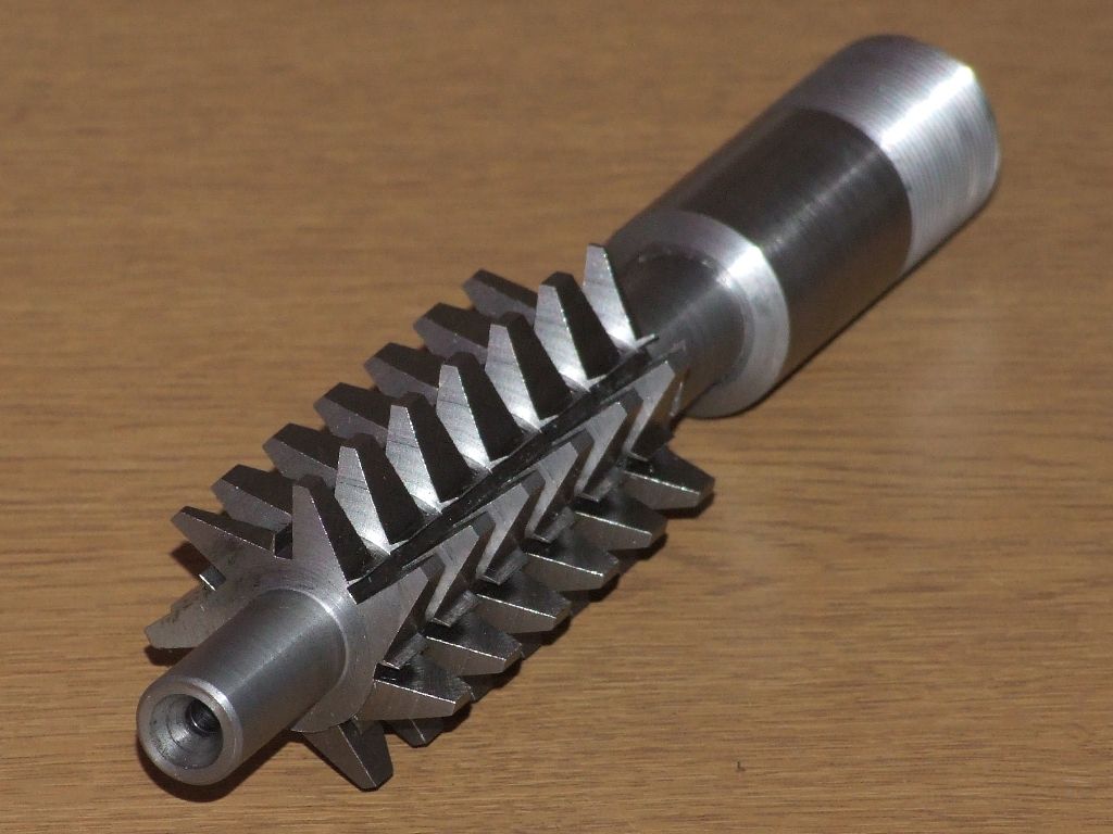
                  1. Make a hobbing cutter from hardenable steel that mimics the worm you will make with added clearance. Harden it and grind the cutter teeth sharp.

                  Not that difficult although it did take some time; I didn't need to grind anything. Reliefs were added with a file before hardening and tempering:

                  worm gear cutter.jpg

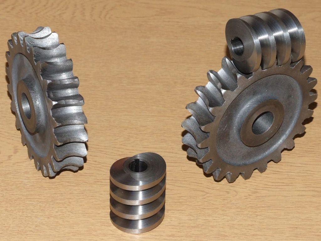
                  The worms and worm wheels, for scale the worm wheels are around 4" in diameter:

                  worms and worm gears.jpg

                  Andrew

                  #563115
                  brian jones 11
                  Participant
                    @brianjones11

                    Something intriguing I noticed, but i expect you all knew this, is that a rack and pinion system uses a 20deg PA form but the rack is a straight 60deg form.laugh

                    #563116
                    brian jones 11
                    Participant
                      @brianjones11

                      Well AJ excluding cnc I cant see how you made that on Maureen BTSOOMcrook

                      #563118
                      Anonymous

                        The helix was cut on a CNC mill for historical reasons, but everything else (hob and parts) were machined on a manual lathe and a big old horizontal mill that cost me £175.

                        Andrew

                        #563137
                        Jan B
                        Participant
                          @janb

                          “Something intriguing I noticed, but i expect you all knew this, is that a rack and pinion system uses a 20deg PA form but the rack is straight 60deg form.”

                          No this is wrong, if using a pinion with 20deg PA then the rack also must have a PA of 20deg.

                          Where do you get the 60deg from?

                          Jan

                          #563138
                          brian jones 11
                          Participant
                            @brianjones11

                            Its the unified thread angle

                            #563139
                            Michael Gilligan
                            Participant
                              @michaelgilligan61133

                              Pressure angle and thread angle are not the same thing

                              … But I’m sure you must know that.

                              MichaelG.

                              .

                              Useful animation towards to bottom of this page:

                              https://www.chiefdelphi.com/t/turning-down-the-od-of-a-gear/137417/20

                              Edited By Michael Gilligan on 17/09/2021 10:27:08

                              #563148
                              Jan B
                              Participant
                                @janb

                                Yes, of course I know that thread angle and pressure angle are not the same. I misunderstood Brian, sorry.

                                Jan

                                #563149
                                Dave S
                                Participant
                                  @daves59043

                                  Pressure angle and flank angle of an involute rack are the same. the thread is (to all intents) a rack wrapped around a cylinder. (squint a bit and ignore the helix for that approximation).

                                  Thread angle is the included angle, but pressure angle is half that – so a 60 degree thread form should make a 30 degree pressure angle involute.

                                  Dave

                                  #563161
                                  JasonB
                                  Moderator
                                    @jasonb
                                    Posted by brian jones 11 on 17/09/2021 07:58:01:

                                    Something intriguing I noticed, but i expect you all knew this, is that a rack and pinion system uses a 20deg PA form but the rack is a straight 60deg form.laugh

                                    Why do you say "A rack and pinon uses a 20geg pa, "a" rack & pinion could just as well use 14.5pa and is what is likely on your DW and certainly on the Myford

                                    Andrew did point out very early on ( first page) in the thread that you would get something like 30pa using a tap.


                                    Edited By JasonB on 17/09/2021 12:57:28

                                    #563175
                                    brian jones 11
                                    Participant
                                      @brianjones11

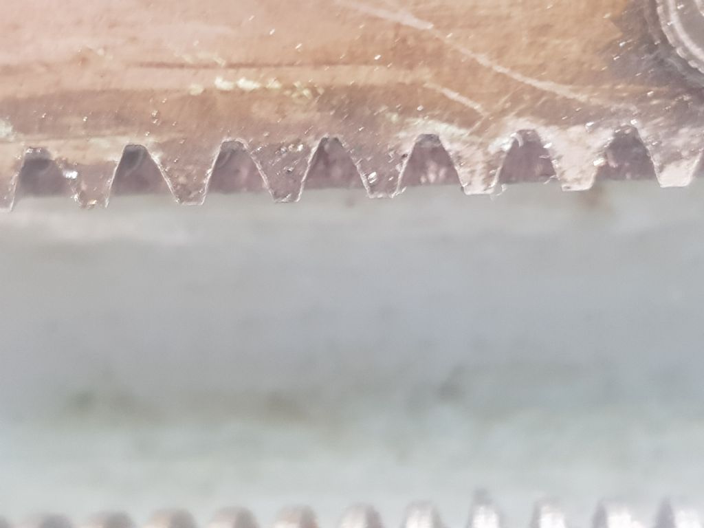
                                      I just read somewhere that a 60 thread angle – Unified produced a 20deg involute pressure angle and a straight line. the hobbing cutter has straight sides but its curved action produces the required 20 deg slope, I wish Id kept the reference, so the rack has straight sides20210917_143657.jpg

                                      I had a look under Maureens apron (she a bit coy about that sort of thing – girls born in the 50's were like that)

                                      As you can see the rack, straight sided teeth 60deg

                                      That animation of meshed gears in the link MG has done my head in

                                      Another avenue of pointless pursuit ahead of me – "life, life, dont talk to me about life" said Marvin the depressed robot

                                      #563184
                                      JasonB
                                      Moderator
                                        @jasonb
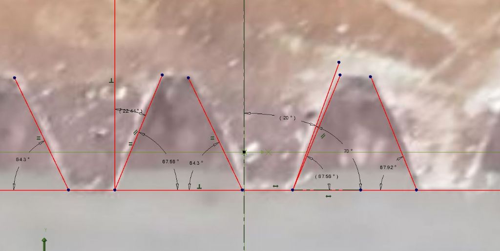
                                        Posted by brian jones 11 on 17/09/2021 14:55:01:

                                        I had a look under Maureens apron

                                        As you can see the rack, straight sided teeth 60deg

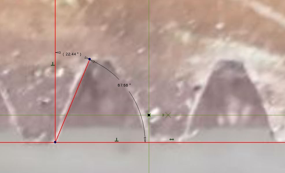
                                        Really, how are you measuring that?

                                        rack angle.jpg

                                        #563186
                                        Martin Connelly
                                        Participant
                                          @martinconnelly55370

                                          Copy your picture into a CAD program and measure the angle. Not 60°. I've done it but will let you find out what it is for yourself.

                                          Martin C

                                          Jason posted just after I started doing it.

                                          Edited By Martin Connelly on 17/09/2021 16:00:39

                                          #563205
                                          brian jones 11
                                          Participant
                                            @brianjones11

                                            Hmm well I was going on what I read, maybe Maureen got a faulty rack?

                                            How do you justify the angle of 67deg?

                                            Now if you postulate Maureen would have had a PA of 14.5deg then the combined angle should be twice that ie 30deg

                                            so if PA was 20deg then this should be 40deg

                                            so this is a long way off?

                                            but note that the rack form has straight sides no involution here. A rack is treated as a gear with infinite PCD

                                            Now PA=14.5 was the historical value from victorian times as giving quiet operation and long wear (but only for medium loads and speeds), The AGMA had better ideas and chose 20deg since 1980 for greater power, reduced pinion teeth before undercutting, wider base (greater no of cycles before fatigue failure), but greater wear.

                                            Whats not to like

                                            #563212
                                            JasonB
                                            Moderator
                                              @jasonb
                                              Posted by brian jones 11 on 17/09/2021 18:29:42:

                                              Now if you postulate Maureen would have had a PA of 14.5deg then the combined angle should be twice that ie 30deg

                                              so if PA was 20deg then this should be 40deg

                                              I was thinking more that the DW gears were 14.5pa rather than any rack.

                                              Quite possible they beefed up the rack and it's pinion to 20pa which is not far off the 22deg measured allowing for the angle of the photo possibly being a bit off

                                              Yes a 20pa cutter would have an included angle of 40deg and a 14.5 pa cutter one of 29deg hence why it was pointed out that your bolt/tap would produce about 30pa due to the 60deg included angle.

                                              #563214
                                              Michael Gilligan
                                              Participant
                                                @michaelgilligan61133

                                                Posted by JasonB on 17/09/2021 15:49:40:

                                                .

                                                rack angle.jpg

                                                .

                                                Could you try nudging that a little, Jason … and maybe get 20° instead of 22.44°

                                                MichaelG.

                                                [ requested before I saw your last post ]

                                                Edited By Michael Gilligan on 17/09/2021 19:03:43

                                                #563216
                                                JasonB
                                                Moderator
                                                  @jasonb

                                                  nudging numbers, I thought that was more Brian's sort of thingsmile p

                                                  There is some distortion, if you look at the notches at each side of Brian's original photo they are leaning so can only take a guess. However we don't really need to do that as if you look under "the Apron" in this old catalogue you can see that they did indeed use 20pa for the rack and it's pinion, must have been thinking of all those model engineers who wanted to use the carriage to plane keyways.

                                                  EDIT, here you go with the others measured and a token 20deg line for good measure.

                                                  Also note that the teeth seem to be slightly concave not "straight" as proclaimed by Brian, maybe after 70yrs of use she is showing some wear and is a bit bow legged under the apron. Click for larger image

                                                  rack angles.jpg


                                                  Edited By JasonB on 17/09/2021 19:21:00

                                                  #563226
                                                  brian jones 11
                                                  Participant
                                                    @brianjones11

                                                    she is showing some wear and is a bit bow legged under the apron.

                                                    kerriste dont say that in front of her, she'll have a cow

                                                    So there's another mystery solved, rack and pinion 20deg PA 40deg apex angle

                                                    now to de-bumf the base angle and unclutter the pitch circle from your diametral pitch and pitch circle. OMG do they make hard work of it all, mixing nomenclature with the cousins

                                                    Are thread forms independent of pcd, so a small pinion has the same tooth form as a large spur for the same circular pitch.(teeth per inch) I dont think it does

                                                    #563228
                                                    Pete Rimmer
                                                    Participant
                                                      @peterimmer30576

                                                      Of course the tooth (not thread) form is different as the PCD changes. That's why we have numbered gear cutters, they are different shapes.

                                                    Viewing 25 posts - 151 through 175 (of 439 total)
                                                    • Please log in to reply to this topic. Registering is free and easy using the links on the menu at the top of this page.

                                                    Advert

                                                    Latest Replies

                                                    Home Forums Workshop Techniques Topics

                                                    Viewing 25 topics - 1 through 25 (of 25 total)
                                                    Viewing 25 topics - 1 through 25 (of 25 total)

                                                    View full reply list.

                                                    Advert

                                                    Newsletter Sign-up