cutting spur gears on a mill

Advert

cutting spur gears on a mill

Home Forums Workshop Techniques cutting spur gears on a mill

Viewing 25 posts - 51 through 75 (of 439 total)
  • Author
    Posts
  • #559252
    JasonB
    Moderator
      @jasonb

      Maybe he also has got a left hand tap winkbut almost impossible to work into the middle of the chevron that way so would as you say John need two separate gears or opposite hand.

      Advert
      #559253
      brian jones 11
      Participant
        @brianjones11

        Pay attention at the back

        Or maybe you don't mean herringbone but just have two straight gears with some angular offset to take up the backlash.

        #559254
        Martin Kyte
        Participant
          @martinkyte99762
          Posted by brian jones 11 on 21/08/2021 13:13:51:

          Well it beats lock down dunnit

          Does someone want to tell him he can come out now

          :O)

          Martin

          #559256
          brian jones 11
          Participant
            @brianjones11

            Now I thought you could do something like that

            The Anderton boat lift used 'herringbone' gears. Big ones. They were cast and then run in pairs in a sand bath to bed them in to my knowledge.

            https://www.alamy.com/anderton-boat-lift-is-a-two-caisson-lift-lock-near-the-village-of-anderton-cheshire-in-north-west-england-image236836670.html

            that should keep the back seat modellers quiet for a while

            BTW have you all spotted the deliberate design error

            #559260
            brian jones 11
            Participant
              @brianjones11
              Posted by John P on 21/08/2021 13:13:22:

              Couple of videos for herringbone fans.

              Don't blink for the second one.

              https://www.youtube.com/watch?v=DFEN9_t150c
              https://www.youtube.com/watch?v=9h7nn1v6D-E

              John

              see what you can do with a big enough tap

              https://www.youtube.com/watch?v=mtV8Zu5EtUE

              #559262
              John P
              Participant
                @johnp77052

                The hand of the tap or hob would have no influence on the
                manufacture of left or right hand helical gears.
                As here in the photo the hob is set over at the helix angle
                and the work is set as here for right hand ,

                right hand.jpg

                and here for left hand.

                gh5.jpg

                John

                #559270
                Martin Connelly
                Participant
                  @martinconnelly55370

                  I presume, Brian, that you are thinking along this line. However these are straight spur gears not helical or herringbone. The problem is that, as pointed out, for a herringbone effect you either need a matching left hand tap or else you need to have a large angular change in the relative position of the tap to the blank. Simply flipping a gear 180° will not change the angle of the teeth to give you a herringbone gear. The introduction of this angular relationship will change the tooth form produced quite substantially.

                  Buy Anti-Backlash Spur Gears | Accu | 500,000+ Components | Accu®

                  Martin C

                  #559271
                  JasonB
                  Moderator
                    @jasonb

                    Thanks John P, a bit like screw cutting away from the chuck, something has to be reversed

                    #559281
                    Martin Kyte
                    Participant
                      @martinkyte99762

                      OK say the tap/hob has a 6 degree helix angle. In order to cut a straight spur gear you angle the tap/hob at 6 degrees to the blank.( Or the blank to the tap/hob). If you increase the angle you get a helical gear of one hand and if you decrease it you get one of the opposite hand.

                      regards Martin

                      #559289
                      Martin Connelly
                      Participant
                        @martinconnelly55370

                        Changing the angle of the tap changes the pitch produced so they may be of opposite hand but they will have different pitches.

                        Martin C

                        #559296
                        Martin Kyte
                        Participant
                          @martinkyte99762

                          No the pitch is set by the TPI of the tap. The approach angle of the cutting edge is set by the skew angle.

                          regards Martin

                          #559313
                          John Haine
                          Participant
                            @johnhaine32865

                            Could we stop calling it a tap when we mean hob? Except of course when talking about trying to use a tap as a hob.

                            Brian, from this response:

                            "Pay attention at the back

                            Or maybe you don't mean herringbone but just have two straight gears with some angular offset to take up the backlash."

                            can we assume that indeed you didn't mean herringbone?

                            #559337
                            Martin Connelly
                            Participant
                              @martinconnelly55370
                              Posted by Martin Kyte on 21/08/2021 19:18:51:

                              No the pitch is set by the TPI of the tap. The approach angle of the cutting edge is set by the skew angle.

                              regards Martin

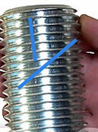
                              thread pitch.jpg

                              Since the original post was regarding using a tap as a hob I will continue to refer to the process of using a tap as a hob. This is clearly not a tap but a bolt but the point is the same regardless, if you change the angle of the tap relative to the axis of the blank you change the pitch of the resulting gear. As I said earlier there is no quick and simple way of cutting accurate gears.

                              Martin C

                              Edited By Martin Connelly on 22/08/2021 08:34:21

                              #559342
                              Martin Kyte
                              Participant
                                @martinkyte99762

                                This is how I see it. In the same way that the pitch of the straight spur gear is dictated by the hob. The hob helix angle setting the set over angle. I agrre that the axial pitch of the helical gear will not be the same as the straight spur gear just by Pythagoras. However once you choose the helix angle of the gear you fix the set over angle of the hob. The pitch is then dictated by the pitch of the hob. You cannot just vary the set over angle to obtain different pitches. If you do you cease to generate an involute and merely alter the shape of the resulting teeth.

                                I'm not clear on how helical gears are specified but the pitch perpendicular to the helix (I would guess at calling it the helical pitch) will be the same as the pitch of the hob.

                                regards Martin

                                #559363
                                John Haine
                                Participant
                                  @johnhaine32865

                                  I've experimented with making a particular sort of helical gear – "helical lever" – which have simple straight sided teeth – they were used by a Victorian clockmaker and can realise large reductions in one stage as you can make one-tooth pinions. I believe that you can hob helical involute gears with a standard hob. From what I recall –

                                  • The "helical pitch" which is measured orthogonal to the teeth is the same as that of the hob.
                                  • The circumferential pitch is increased by a factor 1/cos(helix angle) so the diameter of the gear has to increase as well (as does that of the mating gear of course), by the same factor, to fit in all the teeth.
                                  • Looking at the tooth form along the helix angle it is involute because that's what the hob cuts. This is also what is "seen" by the mating tooth of the other gear which is also helical. It may not be the same as the profile of a cross-section of the tooth.
                                  • You have to angle the hob by whatever its own helix angle is to cut a straight tooth – for a helical tooth you add or subtract the helix angle depending on the handedness you want.
                                  #559364
                                  Howard Lewis
                                  Participant
                                    @howardlewis46836

                                    Purely pedantry, but a helical gear is not a herringbone gear.

                                    It can be paired with a similar one of the opposite helix to produce a herringbone gear, with the Vee tooth pattern.which gives rise to the name.

                                    WHY?

                                    A helical gear, by virtue of its helix angle produces an axial thrust on the shaft. By mounting a gear which is identical, but of opposite helix, the two end thrusts cancel out.

                                    Skew gears are helical gears where the axes of the shafts carrying them are not parallel.

                                    Engineering implies precision. An imprecise description may result in an answer to a question which wasn't asked, and cause confusion.

                                    Howard.

                                    #559366
                                    Martin Kyte
                                    Participant
                                      @martinkyte99762
                                      Posted by John Haine on 22/08/2021 11:23:01:

                                      I've experimented with making a particular sort of helical gear – "helical lever" – which have simple straight sided teeth – they were used by a Victorian clockmaker and can realise large reductions in one stage as you can make one-tooth pinions. I believe that you can hob helical involute gears with a standard hob. From what I recall –

                                      • The "helical pitch" which is measured orthogonal to the teeth is the same as that of the hob.
                                      • The circumferential pitch is increased by a factor 1/cos(helix angle) so the diameter of the gear has to increase as well (as does that of the mating gear of course), by the same factor, to fit in all the teeth.
                                      • Looking at the tooth form along the helix angle it is involute because that's what the hob cuts. This is also what is "seen" by the mating tooth of the other gear which is also helical. It may not be the same as the profile of a cross-section of the tooth.
                                      • You have to angle the hob by whatever its own helix angle is to cut a straight tooth – for a helical tooth you add or subtract the helix angle depending on the handedness you want.

                                      So at least two of us are in agreement.

                                      regards Martin

                                      #559369
                                      John P
                                      Participant
                                        @johnp77052

                                        Trying not to go of topic here. The OP 's aim is to be able to cut gears
                                        using a tap by free hobbing , whilst this can be done as some have shown
                                        on here quite successfully there is always the level of uncertainty as to the finished
                                        result The photo here is a 90 tooth wormwheel cut using a 5/16" tap the finished
                                        job works well using a piece of threaded rod, because this is done using a hobbing
                                        unit you get 90 teeth every time even if the blank is over or under size.

                                        90 tooth worm wheel

                                        90 tooth  18 tpi tap.jpg

                                        It is possible to cut a spur gear using a tap providing the tap is set over at the helix
                                        angle and using the hobbing unit to time the motion .I think is less likely to be able to
                                        do the same with a tap or even a proper hob in a free hobbing situation ,the situation
                                        is worse with a tap and only 4 cutting edges as one cutting edge is disengaged
                                        before the next is engaged so the blank has to revolve 1/4 tooth pitch on its own
                                        with no driving mechanism,the most likely event is the cutting edge strikes the
                                        tooth wiping it out or gouging some of it away.

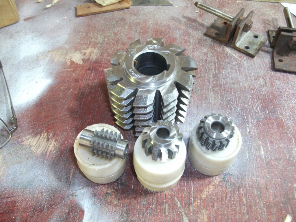
                                        Gear cutting hobs as seen here are mostly all threaded right hand at least all of
                                        mine are ,the helix angle is indicated on the side of the hob,the largest here at
                                        2.5 mod is 2 deg 20 min and the smallest 0.3 mod just over 1/2 deg .Usually
                                        12 tooth the one on the left 0.9 mod made from silver steel flycut form relieved
                                        in 3axis 8 tooth 3 deg helix ,again right hand could just as easily have been cut
                                        left hand reverse the sense of one axis and incline the head 3 deg in the opposite
                                        direction. To the right 0.5 mod 15 tooth Micron hob brand new bought of a junk
                                        stall at ME show for 50 p ,what a bargain.

                                        Gear hobs

                                        hobs.jpg

                                        In setting up the hob is inclined over at the angle indicated so the cutting action
                                        is parallel to the table traverse ,from this spur gears and helical gears may be
                                        generated in left and right hand using the same hob with no errors in pitch.
                                        The spur gears will mesh and run with the helical gears with no problems at all.
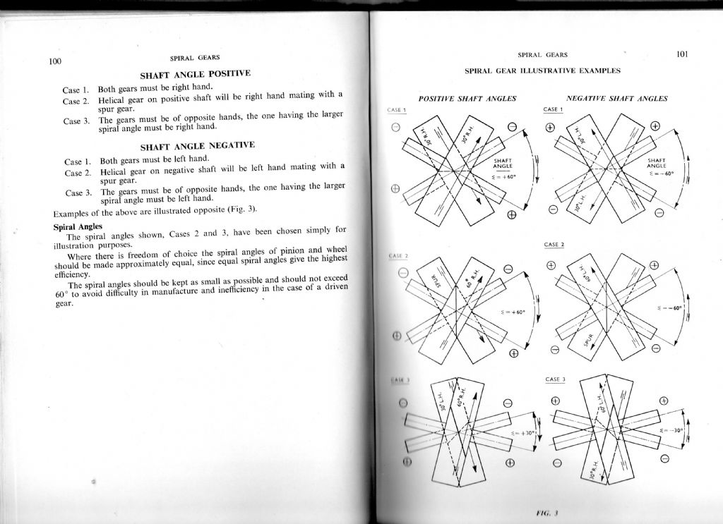
                                        The illustration here show the possible combinations and shaft angles.

                                        Shaft angles.

                                        spiral gears.jpg

                                        Why is this the pitch of the hob dictates the pitch of the gear teeth and since
                                        the set over angle remains the same nothing changes in making any of these gears.
                                        The size of a helical gear will change for a given tooth count according to the
                                        angle of the helix and is calculated by blank divide by cos , angle.

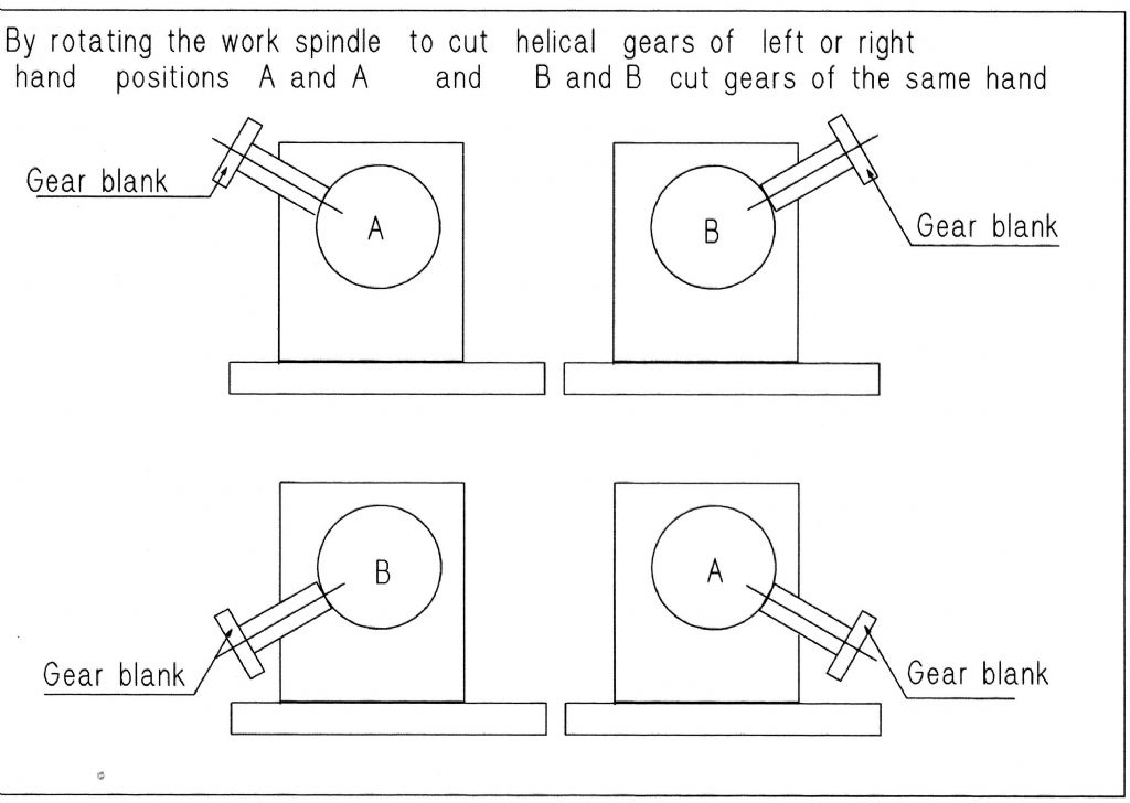
                                        The sketch here shows the hobbing unit work head and the positions to cut
                                        gears of the same hand and opposite hand ,this is really more to do with
                                        accessibility than anything else as there are instances where it is difficult
                                        to either fit the gear blank or get the cutter to a position to make the gear.
                                        As the hobber is connected to the hob electronically there is no problem
                                        in connection with the drive,the work head swings in an arc of about 250 deg.

                                        Work head

                                        workhead.jpg

                                        There is however a variation in pitch if the hob is inclined at greater angle,
                                        an explanation of this can be seen in Ivan Law's book Gears and
                                        gear cutting on page 97 but has no real significance in cutting helical
                                        or spur gears as this can only be used when cutting worm wheels.
                                        At angles below about 3 deg this variation is ignored ,if the angle is greater
                                        the worm is cut to match the worm wheel.

                                        John

                                        #559376
                                        brian jones 11
                                        Participant
                                          @brianjones11

                                          Well this topic has certainly addled a few FES pates, like stirring up the suds sumplaugh

                                          So to demystify the limits of plausible conjecture and give a platform to the deniably involved

                                          What else on lockdown Sunday morning from the desk within my Anderson Shelter

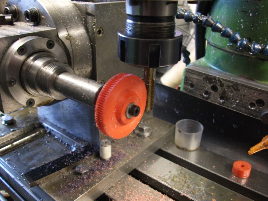
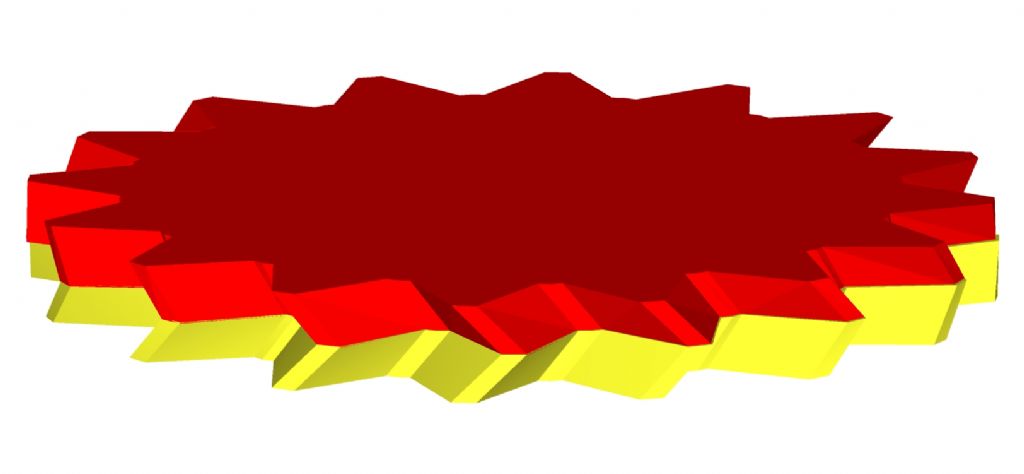
                                          heringbone.jpg


                                          I hope you can see the double helix (truncated Whitworth form BTW). I skewed 6 deg for fun and made from 2 identical blanks chived at the same time

                                          For the follically scarified, note that the yellow gear has been flipped over 180 to make the red

                                          also if you skew one gear wrt the other fractionally then you can mitigate backlash

                                          Now with the appliance of science I shall endeavour to make an animated version showing meshing and also the reviled tap attacking gear blanks

                                          My biggest challenge will be to post mpg or gif on this board, I havent seen any other Disneys on here

                                          Anyone know how its done – maybe Dropbox?, Ive never done a Youtube upload yet (do you have to sell your soul?)

                                          Sorry JP missed your eminent description above, most interesting

                                          As you point out, this OP is not about using hobbing gear and all the expensive industrial attachments involved, way off topic

                                          The point being that a hobbing method ties the spindle mechanically to the mandrel in much the same way as screw cutting on a lathe (excluding the tedious divider plate method)

                                          This is examining whether FREE HOBBING has a place for the hobbyist NPI.  Its clearly demonstrated in making simple worm gears so this is just an extension of the topic. As seen above there are a lot of armchair misconceptions.

                                          One point to note is that theoretical errors can creep in

                                          eg

                                          a) say you want to make a ruler with a 1" block.  Use it to scribe 12 marks then do you have 1ft – well clearly it depends on the accuracy of the block.  Hope you can see the implication of cumulative errors

                                          b) Instead use the basic tech drawing trick use the block to make 12 ticks then project that onto a 1ft line and you have your accurate ruler with 12 inches

                                          So the tap method is using method a)  and the dividing plate (or hob) is using method b)

                                          Now thats the theory but what happens in practice


                                          Edited By brian jones 11 on 22/08/2021 12:44:19

                                          Edited By brian jones 11 on 22/08/2021 12:46:01

                                          #559393
                                          JasonB
                                          Moderator
                                            @jasonb
                                            Posted by brian jones 11 on 22/08/2021 12:18:31:

                                            heringbone.jpg

                                            For the follically scarified, note that the yellow gear has been flipped over 180 to make the red

                                            But it does not work like that with a metal gear. simply flipping it over won't have your teeth running in the opposite direction, that is why I thought you may have a left hand tap or as John has shown will need to cut a left and rright helix pair and butt them together

                                            Easy way to check it is to draw a diagonal line on the side of a disc or cylinder and then flip it over with line still facing you and you will see it is still at the same angle.

                                            #559397
                                            brian jones 11
                                            Participant
                                              @brianjones11

                                              OMG the Monsignor is RIGHT

                                              10^3 apologies, I have flipped my gear blank wrongly????????. I will have to investigate

                                              You do indeed have to angle the tap anti clockwise 11.4 deg for a 10 tpi (5.711deg ha)

                                              GOT IT

                                              My gear flipping created a mirror image which reverses LH to RH

                                              Wow thats an easy mistake to make

                                              Edited By brian jones 11 on 22/08/2021 13:45:03

                                              #559401
                                              brian jones 11
                                              Participant
                                                @brianjones11

                                                All my years in CAD and I never appreciated or noticed the difference between flipping and rotating 180

                                                Gobsmacked – how many hidden errors did that create?

                                                Still my by bridges are still standing but Hammersmith is in trouble but I have a cunning plan

                                                #559559
                                                brian jones 11
                                                Participant
                                                  @brianjones11

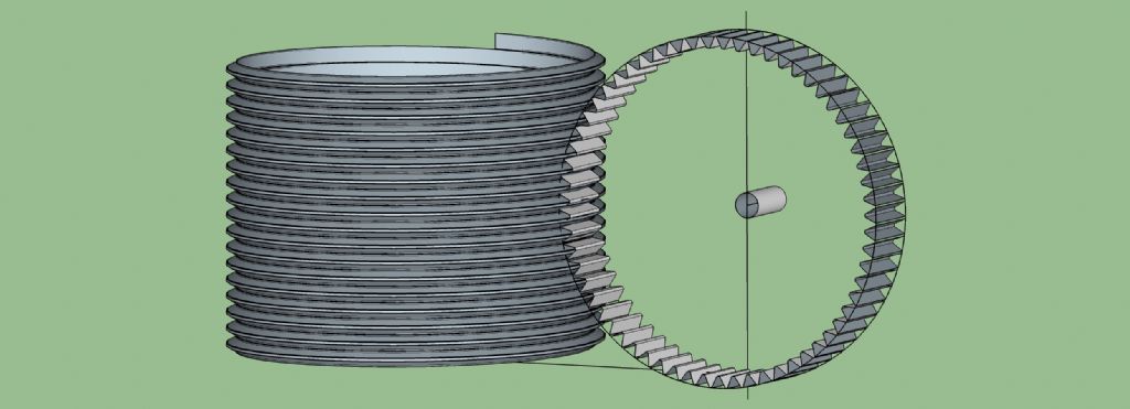
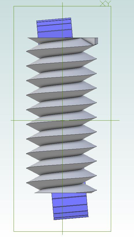
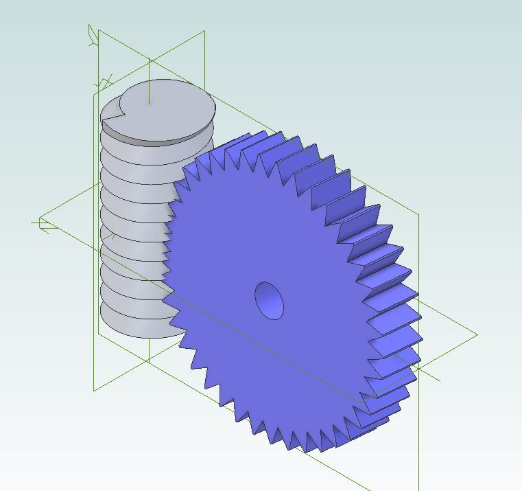
                                                  I thought I could pluck a ready made model of a whitworth threaded rod/bolt easily, turns out to be all clickbait stuff so had to start from scratch which also turned out i will gouge some flutes tomorrow

                                                  I still have a cunning plan

                                                  helix base whitworth v8-1.jpg

                                                  I wonder if a spiral tap might solve the problem

                                                  Edited By brian jones 11 on 23/08/2021 20:37:46

                                                  #559563
                                                  JasonB
                                                  Moderator
                                                    @jasonb

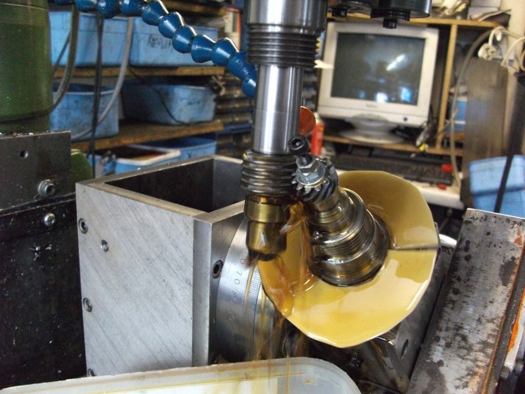
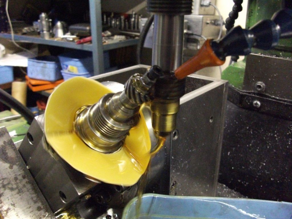
                                                    Brian looking at your sketch t looks like you have the tap(hob) vertical which is OK but you also seem to have shown the gear blank with it's axis horizontal rather than tilted by the helix angle of the tap. Unless the much larger diameter tap you are now using has a very shallow helix angle that means the tilt of the gear can't be seen. If you don't tilt the gear axis the tap will act like a roughing mill and just chew its way into the gear.

                                                    This is with a 1/2" tap

                                                    taphob1.jpg

                                                    taphob2.jpg

                                                    #559566
                                                    brian jones 11
                                                    Participant
                                                      @brianjones11

                                                      Yes JB indeed my model needs more realistic sizing. By the time I had sorted my cad problems I was knackered

                                                      What do you think of a spiral tap?

                                                    Viewing 25 posts - 51 through 75 (of 439 total)
                                                    • Please log in to reply to this topic. Registering is free and easy using the links on the menu at the top of this page.

                                                    Advert

                                                    Latest Replies

                                                    Home Forums Workshop Techniques Topics

                                                    Viewing 25 topics - 1 through 25 (of 25 total)
                                                    Viewing 25 topics - 1 through 25 (of 25 total)

                                                    View full reply list.

                                                    Advert

                                                    Newsletter Sign-up