cutting spur gears on a mill

Advert

cutting spur gears on a mill

Home Forums Workshop Techniques cutting spur gears on a mill

Viewing 14 posts - 426 through 439 (of 439 total)
  • Author
    Posts
  • #566407
    Martin Kyte
    Participant
      @martinkyte99762

      Thanks Dave.

      I do understand what you are getting at. Any deviation from the ideal surface could be termed an approximation to form but as I say lumping everything into one term is not helpfull to any discussion. I think you have answered the question really when you equate the grinding wheel to a hobb with millions of gashes. All that changes is the surface finish.

      regards Martin

      Advert
      #566408
      Michael Gilligan
      Participant
        @michaelgilligan61133
        Posted by Martin Kyte on 11/10/2021 11:16:22:

        Posted by Dave S on 11/10/2021 10:48:54:

        From a pendants point of view […]

        Please don't call me a pedant. […]

        .

        He didn’t … he called you a pendant

        [ perhaps hanging on your every word ]

        angel MichaelG.

        #566410
        Dave S
        Participant
          @daves59043

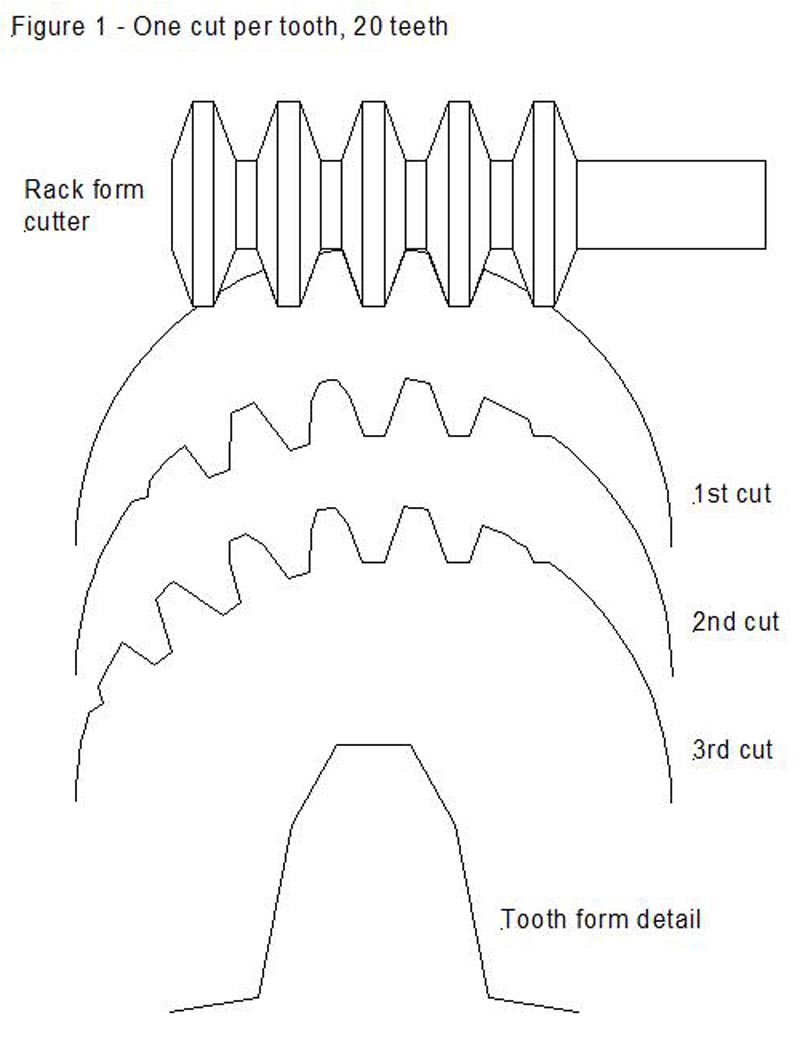
          As a thought experiment imagine a hob with a single gash.
          We will have to assume that the formed cutting tooth is smalle enough to escape fromt he nascent gear during the hobbing rotation, to line it up with the next tooth.
          As a basis for this Tony Jeffrey has a nice picture on his site on the page about rackform hobs. http://www.jeffree.co.uk/pages/multi-tooth-gear-cutter.htm

          Tonys nice picture

          If you visualise the hob as having a single gash then the top of the picture shows all the places that you are cutting on a single hob rotation.
          Then the blank rotates in the helix and you make another cut. With a single gash the blank has to rotate a full tooth space before the next cut is made.
          The end tooth form you will achieve is that of the tooth form detail – an obviously faceted shape.

          Further down the page Tony illustrates how by 4 cuts per tooth (in other words a hob with 4 gashes) gets much closer to the correct form – to the point that although the tooth must have flats on it – it can be no other way with a straight sided cutter – the approximation to a curve is such that it would be easy to miss, and for all practical purposes is an involute.

          Dave

          #566413
          Martin Kyte
          Participant
            @martinkyte99762

            But there is always one point on the rack where the cutter is exactly on the involute. With three cuts there will be three points on each flank where the cut and the involute touch. So the rack exactly follows the path of the involute. Increasing the number of cuts per degree of rotation is just the same as dialing in a finer feed on the lathe.

            regards Martin

            #566430
            SillyOldDuffer
            Moderator
              @sillyoldduffer

              Duncan Webster helped me out last month by writing a program in Python3 to draw involute gears. (I was and still am struggling with the maths!) Duncan's code, which requires the easygraphics module, is here on Dropbox.

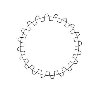
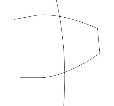
              Duncan's teeth aren't drawn with curves, instead the involute is approximated by drawing a series of straight lines, i.e. facets. By default, the teeth are drawn with 12 facets, so a 20 tooth Mod 1 gear looks like this:

              fullgear20.jpg

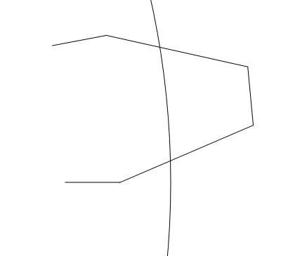
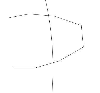
              I bodged Duncan's code to draw only one tooth with 1,2,3,4 and 8 facets, all scaled up so the eye can see the facets.

              Single facet teeth are obviously notchy:

              onefacet.jpg

              Two facets are a considerable improvement:

              twofacets.jpg

              Four facets are quite good:

              fourfacets.jpg

              And at this scale, eight facets are almost indistinguishable from a true curve.

              eightfacets.jpg

              All of these 'involutes' are approximations because of the way they are generated by drawing straight lines, but there are more issues to come.

              Duncan's program could be modified to produce G-code to make subtractive gears with a CNC mill or additive gears with a 3D printer. In both cases his mathematical involute could be an excellent approximation, say 24 facets or more, but the resulting gear will be degraded by the production process. Although both gears can be improved by cleaning up if necessary, the plastic and metal versions differ in strength while the metal version could also be greatly improved by polishing and hardening. The properties of a Duncan gear depend on the maths, the material, the basic production process, and the finishing. It's possible for Duncan gears to be either cheaply or better made as required. Most engineering objects are like this. They can be made up to an advanced specification or down to a price. Both useful, but don't waste money on uneccessarily expensive gear or on on cheap junk. It's the engineer's job to make cost effective choices.

              My general point was lathe change-gears ain't anything special, and that it doesn't matter as long as they do the job.

              Dave

              #566446
              Dave S
              Participant
                @daves59043

                Indeed more cuts is a bit like a finer lathe feed, but the difference is that the lathe will still turn round (form) with either.

                The hob with “courser feed” (1 gash in extremity) creates a different, more approximate form.

                The other difference is that the hobs “feed” is set at manufacture but the number of gashes.

                The thing to remember is that even a couple of gashes gets you a very close approximation of the correct form, and by the time you have a typical number of gashes in a commercial hob the form is essentially perfect, and other factors in machining are likely to have at least as big an effect on the perfection of form.

                Dave

                #566447
                John Haine
                Participant
                  @johnhaine32865

                  Nice! And thanks for the link to the code, and Duncan thanks for generating it. I am wondering about writing a Python wizard for gears, this will be very useful to get me started I think.

                  #566448
                  Michael Gilligan
                  Participant
                    @michaelgilligan61133

                    Very useful, Dave [and Duncan] yes

                    MichaelG.

                    .

                    P.S. __ Your final point is valid, Dave … but it does depend a little on 'the job'

                    … See my earlier link to the Bryant-Symons lathe

                    … Some people use[d] lathes to do very serious screw-cutting

                    #566472
                    Pete Rimmer
                    Participant
                      @peterimmer30576
                      Posted by Andrew Johnston on 11/10/2021 11:04:15:

                      Posted by Pete Rimmer on 10/10/2021 21:20:16:

                      It produces facets it just doesn't produce flat ones……

                      Unfortunately that is mathematically incorrect. A facet is a feature of a polyhedron, generally of one dimension less than the original object. Assuming that we're discussing 3D Euclidian geometry then a facet will be 2D. By definition that means it exists on a plane and so will be planar, ie, flat.

                      Here's a thought experiment. Let's assume we hob a spur gear of zero width, so the hob teeth only cut when they cross the plane of the blank. As the hob enters the plane of the blank, and exits the other side, it will cut a reproduction of its shape, ie, straight sided. Since the blank is of zero thickness the cut time is also zero, so there is no rotation of the blank during the cut to consider. What will the resultant shape of the cut space be; a series of straight lines, or a smooth curve?

                      Andrew

                      I don't do theroetical debate very well I see it as wasted energy. I take your point about the use of the term 'facet' but it's the most fitting terminology I could come up with.

                      Basically my hobber when it's feeding has very little infeed in fact the feed handle moves like clock's minute hand. Almost all of the 'movement' is the hob teeth passing the blank whilst the blank is constantly rolling so whilst a zero-thickness blank might theoretically receive a flat facet cut ANY thickness of blank will be cut via a simultaeneous action of helical-motion teeth passing through the part whilst it's rolling. It will generate a curve, not a flat.

                      #574229
                      John Haine
                      Participant
                        @johnhaine32865

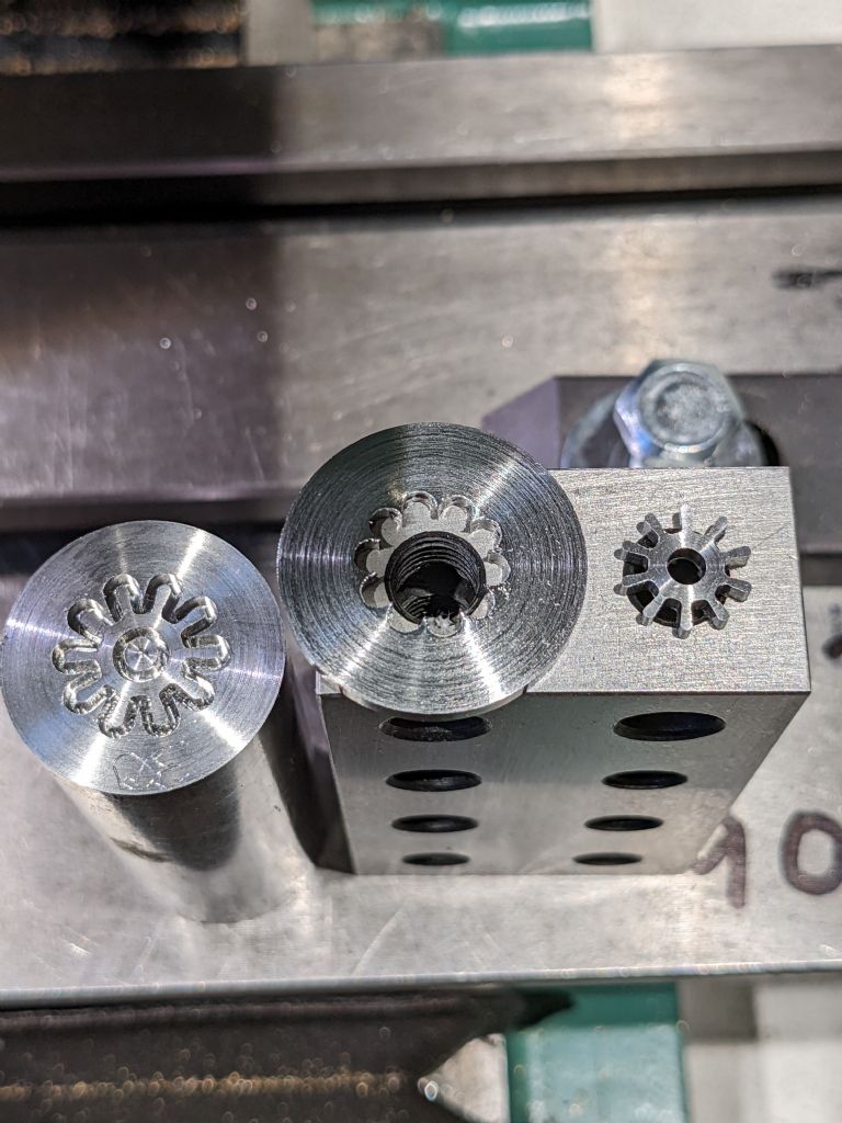
                        I just thought that I'd post a few pics here of some clock gears just made on the vertical mill, profiled out using a small end mill. The gear profiles were generated using Rainer Hessmer's Cycloidal Gear Builder, then the dxf files imported into CamBam for crossing out the wheels and generating the g-code. Pinions were milled into the end of a 1" FCMS bar held in a vertically mounted ER40 collet block, then parted off. I do 2 pinions one on either end of the bar at a time.

                        pxl_20211204_112143929.jpg

                        T

                        From L to R this shows the bar with one pinion ready for parting off; what's left when you part a pinion, and the parted pinion on the right. This is a 10t M1.0 pinion, the one still "embedded" is 1.25 module. These go with mating wheels in the "minutes / hours" 12:1 reduction – they have different modules so the arbor spacings are the same.

                        pxl_20211122_135045282.jpg

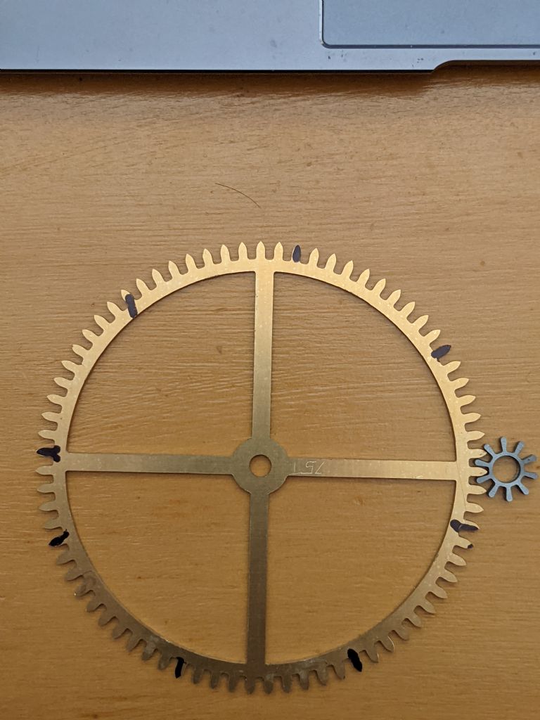
                        This is a 75t wheel/pinion pair with M1.27 for the seconds/minutes reduction.

                        All these cut with a 1mm 2-flute end mill. I haven't managed to break one yet!

                        #574362
                        Martin Kyte
                        Participant
                          @martinkyte99762

                          Free cutting Mild Steel is a little soft for a pinion don't you think especially as it seems the same thickness as the wheel. Maybe this was just a demo piece?

                          regards Martin

                          #574370
                          John Haine
                          Participant
                            @johnhaine32865

                            Normally yes, but this is motion work driven by a stepper motor so minimal torque transmission.

                            #574374
                            John Haine
                            Participant
                              @johnhaine32865

                              Wheel is 1.5, pinion 2.5mm.

                              #574377
                              Martin Kyte
                              Participant
                                @martinkyte99762
                                Posted by John Haine on 05/12/2021 19:15:54:

                                Normally yes, but this is motion work driven by a stepper motor so minimal torque transmission.

                                Ah, that would explain it.

                                regards Martin

                              Viewing 14 posts - 426 through 439 (of 439 total)
                              • Please log in to reply to this topic. Registering is free and easy using the links on the menu at the top of this page.

                              Advert

                              Latest Replies

                              Home Forums Workshop Techniques Topics

                              Viewing 25 topics - 1 through 25 (of 25 total)
                              Viewing 25 topics - 1 through 25 (of 25 total)

                              View full reply list.

                              Advert

                              Newsletter Sign-up