cutting spur gears on a mill

Advert

cutting spur gears on a mill

Home Forums Workshop Techniques cutting spur gears on a mill

Viewing 25 posts - 401 through 425 (of 439 total)
  • Author
    Posts
  • #566274
    JasonB
    Moderator
      @jasonb
      Posted by SillyOldDuffer on 10/10/2021 10:55:19:

      Posted by Nigel Graham 2 on 10/10/2021 00:01:52:

      I must admit I have never thought the headstock gears and the change-wheels on my ML7 either "crude" or "square"; whatever those were meant to mean. If my screw-cutting comes out ragged, I blame the operator not the machine!

      Myford and most other lathe gears are 'good enough' rather than well made. The main disadvantage of their relative crudeness and imperfect curves is noise. Vintage car gearboxes use basic gears and the whine is all too obvious, but lathe gears don't work that hard. Backlash is also evident, but doesn't matter when screw-cutting or anything else lathe related.

      Putting the best possible gearing into a lathe is a waste of money unless the machine needs to be as quiet as possible or is exceptionally powerful. Myford lathes, bless 'em, aren't powerful!

      Dave


      Must say when I had my geared head Emco there were no crude " lathe gears" or short cuts taken with the gearing and I seem to remember earlier in this thread Andrew mentioned helical gears on lathes to reduce noise.

      As for straight teeth, really depends on what change gear you pick up and look at, my small 25T ones certainly have as easily seen curve to them compared to the largest 80T even without using a microscope. If I had a 127T gear I would not be expecting to see much of  a curve on that either.

      Backlash on the screwcutting banjo is really all down to how the user positions the gears as the ctrs and therefor PCD are not fixed.

      Edited By JasonB on 10/10/2021 13:21:12

      Advert
      #566282
      SillyOldDuffer
      Moderator
        @sillyoldduffer
        Posted by JasonB on 10/10/2021 13:17:47:

        Posted by SillyOldDuffer on 10/10/2021 10:55:19:

        Posted by Nigel Graham 2 on 10/10/2021 00:01:52:

        I must admit I have never thought the headstock gears and the change-wheels on my ML7 either "crude" or "square"; whatever those were meant to mean. If my screw-cutting comes out ragged, I blame the operator not the machine!

        Myford and most other lathe gears are 'good enough' rather than well made. …

        Dave

        Must say when I had my geared head Emco there were no crude " lathe gears" or short cuts taken with the gearing …

        Backlash on the screwcutting banjo is really all down to how the user positions the gears as the ctrs and therefor PCD are not fixed.

        Edited By JasonB on 10/10/2021 13:21:12

        Perhaps we should have a lathe gear beauty contest, with close-up photos of tooth form and carefully measured dimensions! I'm not suggesting lathe gears are rubbish, simply that they're not wonderful because they don't have to be!

        • Cast gears will always be dubious, some much better than others depending on exactly how they were made.
        • Hob made gears are an approximation, again some better than others
        • Generated gears, such as Sunderland, are usually good, but they too can be approximated.

        What does good look like? I suggest true centre running with accurate diameters throughout plus close to involute curves, with teeth polished, chamfered and hardened. No need to adjust mesh with a sheet of paper as normally necessary with change gears.

        The gears in my theodolite are more like it, but then they really do need to be good.

        Dave

        #566284
        JasonB
        Moderator
          @jasonb

          Dave the reason why lathe change gears are often done with a strip of paper is that it is a darn sight easler than calculating the PCD for the pair and trying to set the banjo studs to that PCD. Also has the benafit of compensation for worn studs and bushes on the machine as well as any wear on the gears

          Funny enough I've just taken some photos, will post in a while.

          #566289
          JasonB
          Moderator
            @jasonb

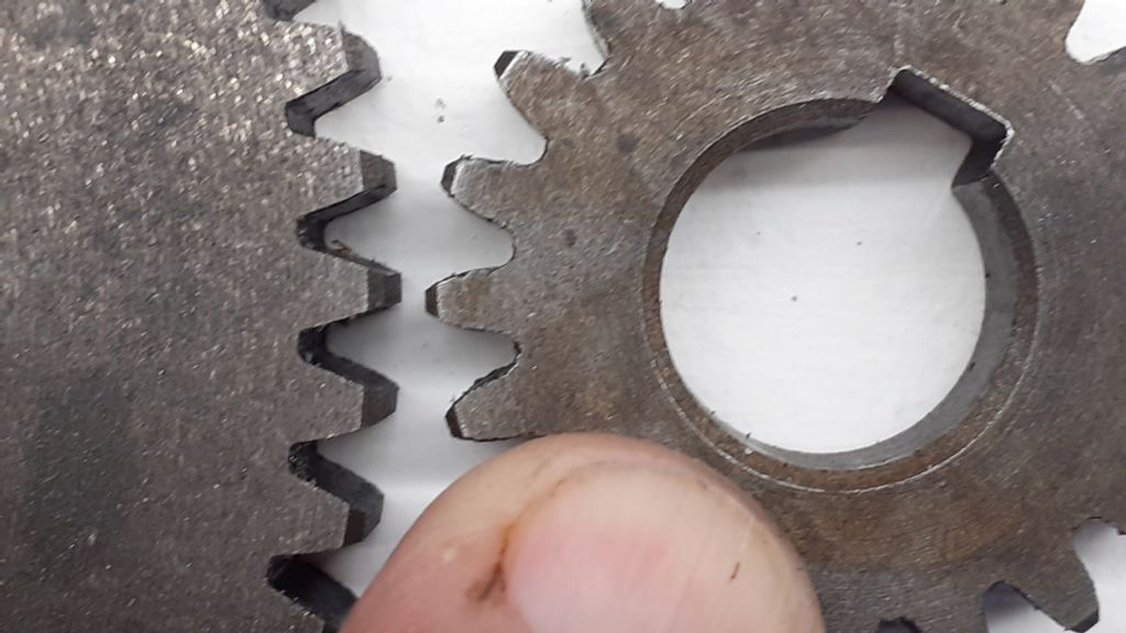
            So as I said it really depends on what gear you pick up and look at as to whether it looks straight or not. Here we have the 25T and 70T change gears from my lathe which are MOD1.5 20pa, easy to see the smaller gear on the right has more curve than the larger one on the left though I can still see a small amount of curve on that.

            20211010_145440.jpg


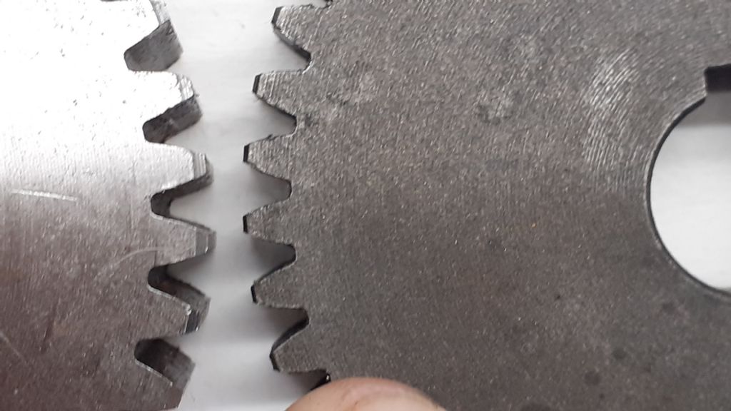
            Next lets compare the lathe change wheel with a bought in commercial gear of reasonable price from Belting on line. 45T change wheel on right, 46T bought in on left not a lot of difference, both show curves.20211010_145516.jpg

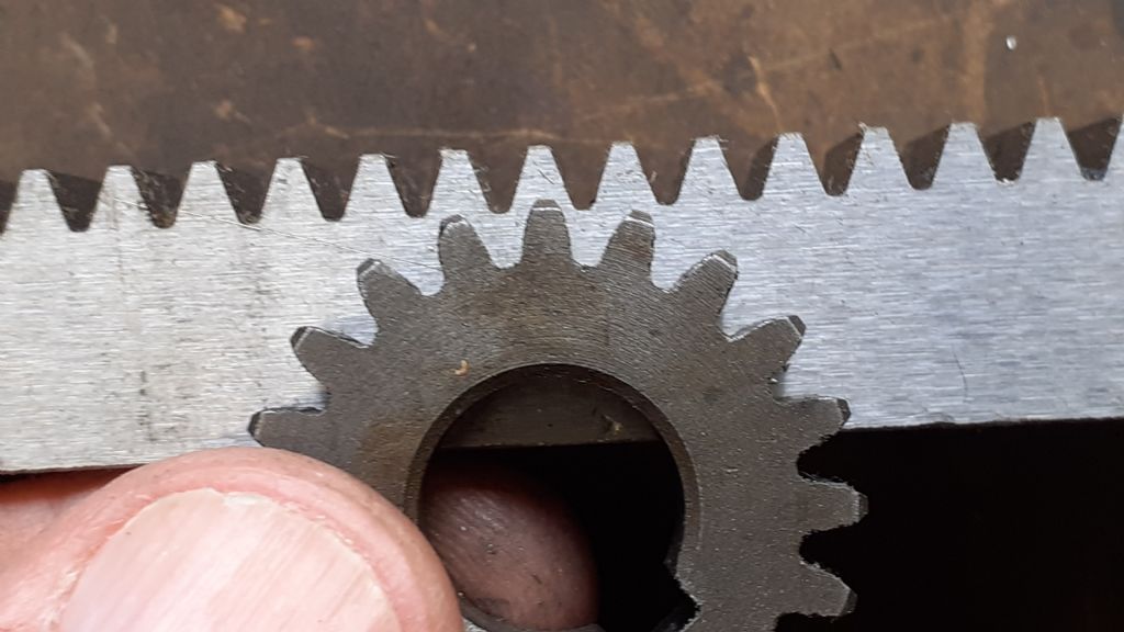
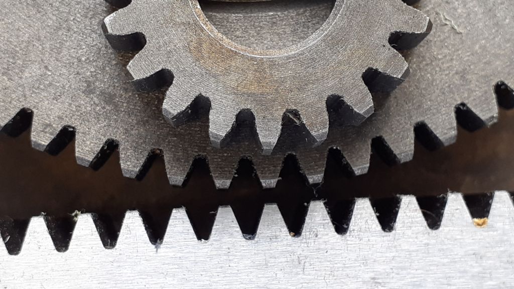
            If we now lay the gears on a rack it is easy to compare the straight sides of the rack to the shape of the gear teeth, 25T first

            20211010_145637.jpg

            Then 70T

            20211010_145727.jpg

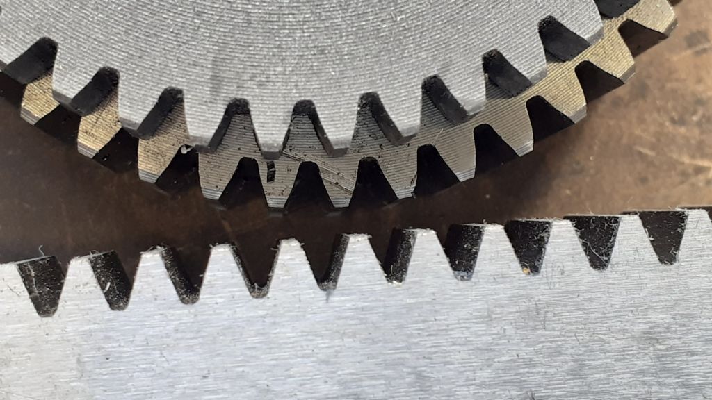
            Now the 45T lathe gear laid on top of the 46T commercial held opposite the rack

            20211010_145902.jpg

            Finally the 25T and 70T against the rack

            20211010_150136.jpg

            So I would conclude that my far eastern lathe change gears are not a lot of difference to commercial gears and certainly none are straight which makes me wonder why if Myford ones are straight people pay good money for them. devil

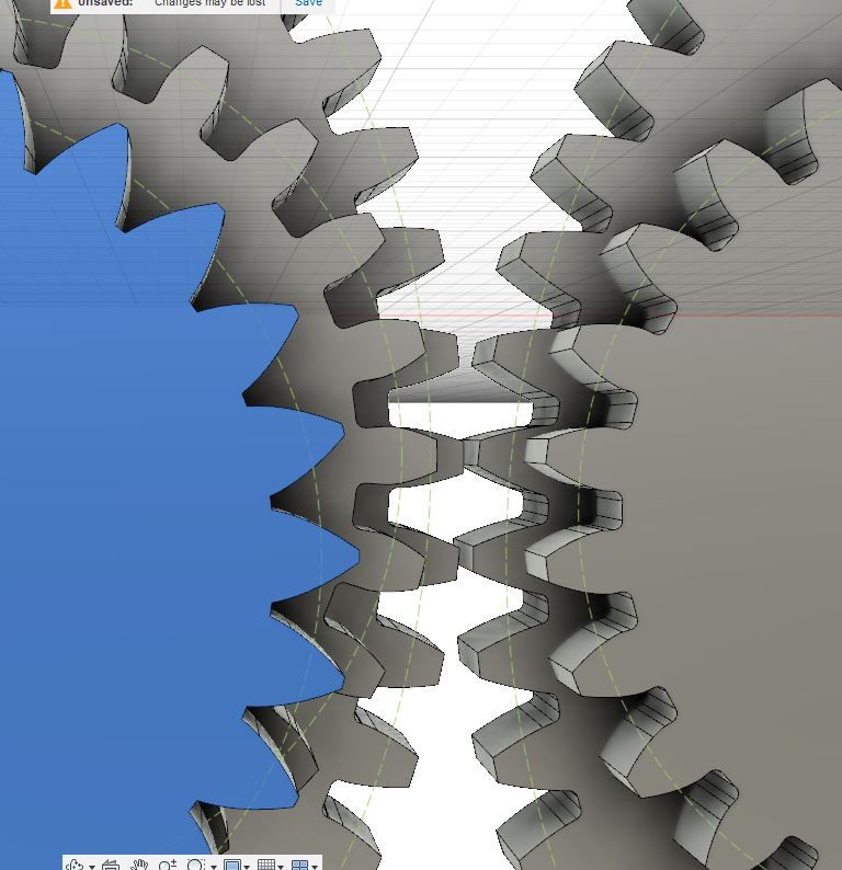
            Now if I wanted some cheap plastic gears as I have said before 3D printing would be the best way to go. For that you need a 3D model to print so here we have 25T gears laid on 80T gears, 20pa on the right, 14.5 pa on the left and all com out with correctly curved faces using the CAD to generate the tooth form also predictable tooth count. PCD, profile, PA etc.

            pa.jpg

            Edited By JasonB on 10/10/2021 16:17:44

            #566293
            Michael Gilligan
            Participant
              @michaelgilligan61133

              Posted by JasonB on 10/10/2021 16:14:57:

              […]

              So I would conclude that my far eastern lathe change gears are not a lot of difference to commercial gears and certainly none are straight which makes me wonder why if Myford ones are straight people pay good money for them. devil

              […]

              .

              Myford change gears are 14.5° Pressure Angle

              To the uninitiated free-hobber, they might therefore appear straight [ish]

              MichaelG.

              #566295
              JasonB
              Moderator
                @jasonb

                Indeed and that was one of the reasons I included the last image from F360 and there is not a lot of difference between the two so if visible on a 20pa should be on a 14.5pa too subject to tooth count.

                #566296
                JasonB
                Moderator
                  @jasonb

                  here is what the uninitiated free-hobber may end up with if using a 60deg thread form tap or bolt as a hob laid ontop of the 14.5pa gears this one luckily to turn out to be 25T

                  30pa.jpg

                  #566299
                  duncan webster 1
                  Participant
                    @duncanwebster1
                    ……….

                    • Hob made gears are an approximation, again some better than others

                    ……

                    Dave

                    you'll have to justify that one, gears made with shaped cutters one tooth at a time are an approximation except for the exact tooth they are designed for, but hobbing is surely a generating process

                    #566304
                    Dave S
                    Participant
                      @daves59043

                      Hobbed gears have the same number of facets as the number of tooth gashes in the hob iirc.

                      So they are an approximation to the involute which usually have many facets.

                      Dave

                      #566306
                      Michael Gilligan
                      Participant
                        @michaelgilligan61133
                        Posted by JasonB on 10/10/2021 17:01:22:

                        here is what the uninitiated free-hobber may end up with if using a 60deg thread form tap or bolt as a hob laid ontop of the 14.5pa gears […]

                        .

                        Q.E.D. yes

                        MichaelG.

                        #566310
                        duncan webster 1
                        Participant
                          @duncanwebster1
                          Posted by Dave S on 10/10/2021 18:24:04:

                          Hobbed gears have the same number of facets as the number of tooth gashes in the hob iirc.

                          So they are an approximation to the involute which usually have many facets.

                          Dave

                          Well the link doesn't agree with that statement Practical Machinist, I've extracted the important bit.

                          Quote:


                          Originally Posted by EPAIII View Post

                          This is not really true. A hob has straight sides on it's teeth and therefore it cuts a series of flat facets for the gear tooth face. Thus the hob shown in post #9 has ten rows of teeth and will form a tooth with ten flats on each tooth face that approximate the involute curve. The more rows of teeth on the hob, the better the approximation. But it is not a "perfect" involute. It would take a hob with an infinite number of teeth to produce a perfect curve.


                          I don't know where you learned this, or whether you worked it out from first principles, but it's flat out wrong. I'm sorry to contradict you publicly and have no wish to cross swords, but it seems to me your post is just too misleading (and yet plausible and authoritative) to be left unchallenged on a fairly respected forum like this.

                          Hobbing is a generating process, which generates a true involute curve from a virtual straight sided 'rack' tooth form.

                          Provided it's set up in a hobbing configuration, correct involute teeth at any viable tooth count can be generated with a single tooth hob (ie a flycutter), if you have plenty of time to spare. Even in specialist gearcutting jobbing shops this is sometimes done for one-off tooth forms, for which the need is unlikely to recur.

                          Perhaps you're confusing hobbing with the hybrid sometimes adopted in home shops, using something which looks like a hob but with zero helix angle. Essentially it's like a stack of several form cutters, except the form is straight sided. The quasi-hob is disposed and traversed at right angles across the stationary workpiece (unlike a hob).

                          #566312
                          Pete Rimmer
                          Participant
                            @peterimmer30576

                            The gear blank does not stop rotating for each hob tooth to make a cut, so each cut is made not with a flat facet but with a slight rolling action.

                            Think of it as analogous to filing a curved face in a part. The file is flat but you generate the curve by rolling the file as you push. Hobbing is similar.

                            Edited By Pete Rimmer on 10/10/2021 20:09:44

                            #566315
                            Michael Gilligan
                            Participant
                              @michaelgilligan61133

                              This little book from 1914 might be considered the definitive text: **LINK**

                              https://archive.org/details/hobsgearhobbing00edgarich

                              .

                              I was certainly impressed

                              MichaelG.

                              #566316
                              Anonymous

                                Here's an alternative viewpoint from a company that made gear hobbing and metrology machines:

                                Gear Hobbing

                                Note: the US arm seems to have disappeared, by Koepfer still exist in Germany, producing high performance gears.

                                If a hob produces a mathematically correct involute curve rather than a series of facets why do some gears need to be shaved after hobbing to improve profile and reduce running noise?

                                Andrew

                                #566318
                                Pete Rimmer
                                Participant
                                  @peterimmer30576

                                  It produces facets it just doesn't produce flat ones. In a similar vein who would argue that a lathe can't produce a smooth round finish even though it's using a tool that inherently cuts a helix?

                                  It's all a matter of degree.

                                  #566342
                                  DC31k
                                  Participant
                                    @dc31k
                                    Posted by Andrew Johnston on 10/10/2021 20:47:33:

                                    If a hob produces a mathematically correct involute curve rather than a series of facets why do some gears need to be shaved after hobbing to improve profile and reduce running noise?

                                    What you are asking is precisely analogous to asking why turned parts need to be ground or lapped after they come off the lathe – the answer being to improve the surface profile.

                                    A great number of the gear finishing tools use the same motion as the gear cutting tools that preceded them, just with a different cutting tool – often an abrasive.

                                    Pete Rimmer's point is very apt. Nobody complains about a lathe producing a helical surface. One can extend his point to the flat surface produced by a shaper or planer – at a microscopic level it is a series of ridges, but the tool/workpiece relative movement is correct.

                                    There is a huge amount of confusion in this place over what constitutes an 'approximate' method. A lot of it is simple misunderstanding of the language used.

                                    A generating process is by definition one in which the movement between cutting tool and workpiece is geometrically (mathematically) correct to produce the shape required. It is a mistake in the use of language to employ 'approximate' to describe a 'generating' action.

                                    Where 'approximate' might gain some foothold is in the _application_ of the method. If you do not let the hob cut 'enough', the sides of the gear teeth will not be well formed (cf roughing cut and finishing cut with a lathe – coarse and fine helix left on the work). The definition of 'enough' is arrived at by the end-use to which the gear is put. Sometimes, even 'forever' is not 'enough' and that is when you have to send the gear to another machine for finishing, just as you would send your planed surface plate to be scraped.

                                    #566348
                                    Dave S
                                    Participant
                                      @daves59043

                                      I think a better definition of a generating process is: “The shape cut by the tool is not the inverse of shape of the tool.”

                                      In other words the cut surface is created by a series of tool / workpiece movements.

                                      Sunderland planing is a generating process – a rack form cutter is applied to a workpiece to create a gear.

                                      Zero helix “hobbing” is also a generating process – one that without any relative rolling movement produces a (quite rough approximation of) an involute.

                                      I’ll see if I can find the reference- I’ve read a lot of gear manufacture articles and books. I’m fairly sure it was a technical paper by a manufacturer of hobs ( not the previously linked one) about why their jobs were superior- because they had more tooth gashes.

                                      It maybe angels dancing in a pin head stuff, but it is no less interesting for that.

                                      Dave

                                      #566366
                                      Dave S
                                      Participant
                                        @daves59043

                                        I've had a poke about and I haven't found the article I thought I was looking for.

                                        However here are a few, from different authors which all state (in summary) that the generation of an involute by a hob is limited in its accuracy by the number of gashes in the hob, and these gashes are each responsible for a facet on the tooth form.
                                        I hadn't picked up the also scalloped effect of the hob, but that also makes sense, and is not present in planed gears.

                                        This (**LINK**) is a comparision of Planing (MAAG is another name for the Sunderland planing process) and hobbing:

                                        End of Page 12:
                                        An appreciable factor in the tooth profile accuracy of
                                        coarse pitch gears with small numbers of teeth is the number
                                        of enveloping cuts available for generatin~ the tooth
                                        profile (Fig. 10). With hobbing, this depends on the number
                                        of gashes on the hob and the number of teeth on the workpiece.
                                        The larger the number of gashes, the larger will be the
                                        series of tangential cuts and therefore the better the
                                        approximation to the ideal involute. The hob outer diameter
                                        however necessarily increases as the number of gashes is
                                        increased, on the assumption that the length of the tooth
                                        does not drop below the economic limit which allows a
                                        . sufficient number of regrinds.

                                        Both these articles from Gear Technology archives also mention it early on:

                                        **LINK**
                                        **LINK**

                                        Incidentally there is a wealth of gear related information in the Gear Technology back issues.

                                        And this paper (**LINK**) is about the process of hobbing on hardened gears – not a common thing as most hardened gears are ground finished.

                                        Pg13 has a nice set of illustrations.

                                        I stand by my original statement.

                                        Dave

                                        #566371
                                        Martin Kyte
                                        Participant
                                          @martinkyte99762

                                          Can we make up our minds as to the difference between surface finish (roughness/facets) and approximations to curves. Hobbs will generate the correct curve but with a degree of surface roughness, form cutters approximate the curve as one cutter serves for a range of teeth but surface roughness will be better. Define the terms better and the confusin dissapears.

                                          regards Martin

                                          Edited By Martin Kyte on 11/10/2021 09:44:16

                                          Edited By Martin Kyte on 11/10/2021 09:45:08

                                          #566380
                                          John Haine
                                          Participant
                                            @johnhaine32865

                                            Interestingly, the most common form cutters actually approximate the involute with a circle at the nominal size, and the approximation gets worse over the range. I've made an experimental version of the cutter with circular form by CNC turning, but it would be just as easy to make it a true involute. I assume that commercial form tools use the same circular approximation?

                                            #566387
                                            Dave S
                                            Participant
                                              @daves59043

                                              From a pendants point of view Hobs approximate (closely or not depending on the hob parameters) the involute curve with a series of straight lines.

                                              The number of gashes on the hob directly relates to the number of straight lines.

                                              This is not a surface roughness thing, its an approximation thing.

                                              From a practical POV even 5 facets is perfectly adequate for most gearing in non critical applications, and the approximation (circular in the case of form cutters or faceted) make no difference. That doesn't mean its is not an approximation.

                                              Dave

                                              #566388
                                              Anonymous
                                                Posted by Pete Rimmer on 10/10/2021 21:20:16:

                                                It produces facets it just doesn't produce flat ones……

                                                Unfortunately that is mathematically incorrect. A facet is a feature of a polyhedron, generally of one dimension less than the original object. Assuming that we're discussing 3D Euclidian geometry then a facet will be 2D. By definition that means it exists on a plane and so will be planar, ie, flat.

                                                Here's a thought experiment. Let's assume we hob a spur gear of zero width, so the hob teeth only cut when they cross the plane of the blank. As the hob enters the plane of the blank, and exits the other side, it will cut a reproduction of its shape, ie, straight sided. Since the blank is of zero thickness the cut time is also zero, so there is no rotation of the blank during the cut to consider. What will the resultant shape of the cut space be; a series of straight lines, or a smooth curve?

                                                Andrew

                                                #566391
                                                Martin Kyte
                                                Participant
                                                  @martinkyte99762
                                                  Posted by Dave S on 11/10/2021 10:48:54:

                                                  From a pendants point of view Hobs approximate (closely or not depending on the hob parameters) the involute curve with a series of straight lines.

                                                  This is not a surface roughness thing, its an approximation thing.

                                                  Dave

                                                  Please don't call me a pedant. Turning marks on a lathe turned cylinder would be referred to as surface roughness. Taper would be the approximation to the correct geometery. Unless you produce a form tool for each tooth count some of the gears are going to be approximations of the curve. Thats geometry. Hobbs will generate the right geometery but create machining facets which is surface finish. Lumping surface finish and geometrical errors into the same bucket makes the discussion woolly.

                                                  regards Martin

                                                  #566398
                                                  duncan webster 1
                                                  Participant
                                                    @duncanwebster1

                                                    Taking Andrews thought experiment, his zero thickness gear will be a series of flats, but if there is another one alongside the flats will have an angular offset, so for a real case there will be a series of spirals. The repeat rate is the same as the cut per tooth, ie a few thou.

                                                    #566404
                                                    Dave S
                                                    Participant
                                                      @daves59043

                                                      Firstly I was mostly calling myself a pedant – for insisting that the hobbed profile is actually a series of facets.

                                                      Apologies if that came across as insulting to anyone.

                                                      In the case of a Lathe turned cylinder, assuming the lathe is in good order the cross section of that cylinder will be circular. (the intended form). There is a helical groove running down the cylinder, which does affect the cylindrical size – crests are larger than troughs. but it does not make the cylinder none circular.* Hence the helix can be described as surface roughness – now close to size (not form) is the cylinder.

                                                      The hobbed gear has both surface roughness issues (its a cutting process and will leave tooth marks after all) AND form issues. The faceting is a departure from the ideal surface form, and hence is more appropriately termed an approximation, just as using a circular form tool cutter is a departure from the idea from, and hence an approximation.

                                                      Gear grinding has 2 benefits. Firstly the cutting tools are capable of taking a much smaller cut – so can leave the surface roughness at a lower level, and secondly there are millions of cutting tools operating all the time – equivalent to a hob with millions of gashes – so the form produced is much more perfect than it would be with the limited number of cuts a hob makes.

                                                      Dave

                                                      *actually it does if you cross section you get an oval with the DOC as you go peak to trough.

                                                    Viewing 25 posts - 401 through 425 (of 439 total)
                                                    • Please log in to reply to this topic. Registering is free and easy using the links on the menu at the top of this page.

                                                    Advert

                                                    Latest Replies

                                                    Home Forums Workshop Techniques Topics

                                                    Viewing 25 topics - 1 through 25 (of 25 total)
                                                    Viewing 25 topics - 1 through 25 (of 25 total)

                                                    View full reply list.

                                                    Advert

                                                    Newsletter Sign-up