Posted by brian jones 11 24/09/2021 14:41:58
ll you needed to know about CP and the Base Bitch
https://www.geartechnology.com/articles/0992/Base_Pitch_Tables/
this past post went into the problems of measuring a gear (as opposed to calcs + suck it and see)
You cant just use calipers / disc mic and measure PCD just like that
https://www.model-engineer.co.uk/forums/postings.asp?th=166048
If you have two gears meshed together you can deduce the pcd from distance between centres
then there's the eyeball method
======================================
The last 2 lines is where Brian's methods of measuring all fall down.
Whilst it is true you can deduce the PCD from the distance between
centres it is of little use if you are making a pair of gears to fit
between pre determined and existing fixed centres ,you would need to be able
to measure the gears with some accuracy before they are removed
from the machine on which they are cut.
Still we have seen from his methods of working from
posting on 13 / 9 / 2021 12:30:19
Difficult to make two gears that will mesh together from fixed centres.
Drill your centers afterwards.
—————————————
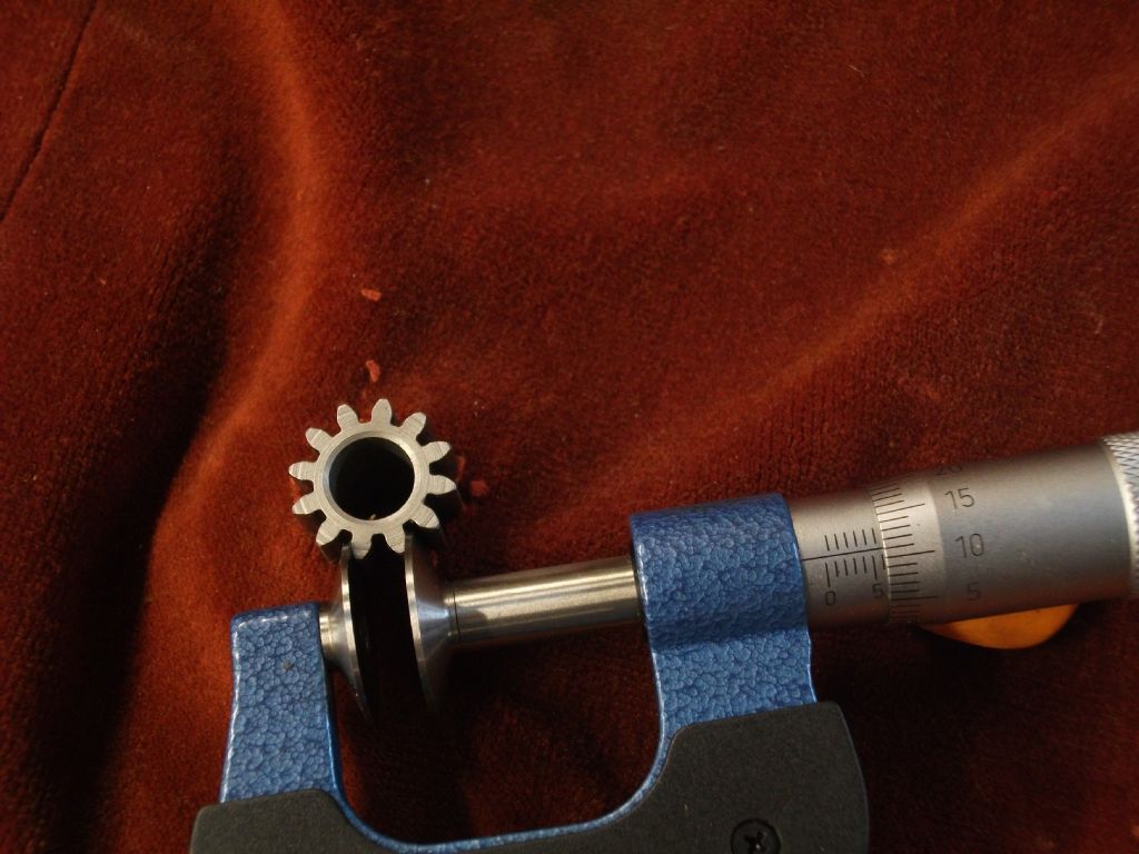
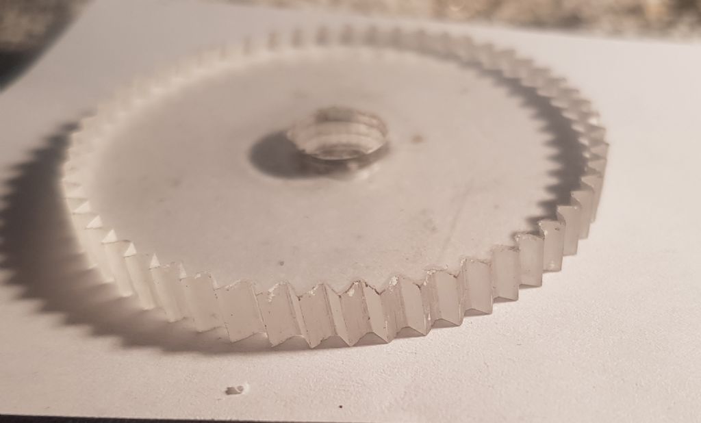
With regard to eyeballing the pressure angle , here is
a small gear the OD is 18.970 mm or .7468", the span across
2 teeth is 6.112 mm as can be best determined from the
micrometer reading.
Now is it possible to eyeball the pressure angle as suggested
by BJ 11 or will a guess do .

There are only 2 options 14.5 deg pa or 20 deg pa.
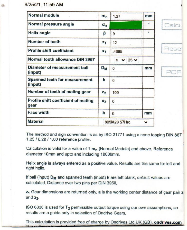
Here are the required inputs for the Ondrives gear tooth
calculator only the input for pa is missing , give it a try
and see which one of the two that it is and how close the
answer is to the micrometer reading. The results for both
are very close but one is a clear leader.

Seeing Andrew's posting 23/09/2021 21:25:25
When I started making gears I spent some time faffing about with gear verniers
I didn't find them easy to use and the results were indifferent. Now I just calculate
the theoretical values and machine to those.
———————————–
I can understand this point of view with the gear tooth calipers ,they always
seemed to me to be a hit and miss method , the span measurement seems to offer
a slightly more accurate solution ,the Ondrives also does give the measurement
across 2 pins which is likely to be the most accurate method obviously the requirement
to grind 2 suitable pins is just more to do.
Hobbing can be different to using form cutters in as much you can keep cutting in
and still retain the tooth form which you can't do with form cutters.Only one of the hob
cutters that i have has the infeed marked on ,using the general recommendation for
cut depth does not work either ,eg in Gears and gear cutting the tooth depth cut
for 20 dp is .108 inch both my 20 dp hobs need to infeed by .1115 inch
to cut to standard form.All of the hobs that Arc Euro used to sell were Topping
cut hobs and still did not conform to standard cut depths,all of this you find out
in time until it is no longer a problem ,being able to measure is just a help.
I suppose it could be time to reflect on the heading of this
thread
cutting spur gears on a mill
and on the first lines
" I have seen vids of using diving head for use with a milling form tool for cutting
a spur gear say 3" dia, 1/4" thick with say 80 teeth
OMG what a painfully slow process as you mill each one"
All of this diversion into the discussion of wind turbines etc has seen a complete
lack of gears made, maybe we will be getting on to hot air engines very soon,
should be enough of it to keep one running until the sun goes dim.
John
Just seen this from BJ: "Maureen has my secret weapon in her jaws I must get on"
Stay tuned for the next thrilling installment!.
John
Martin Kyte.


