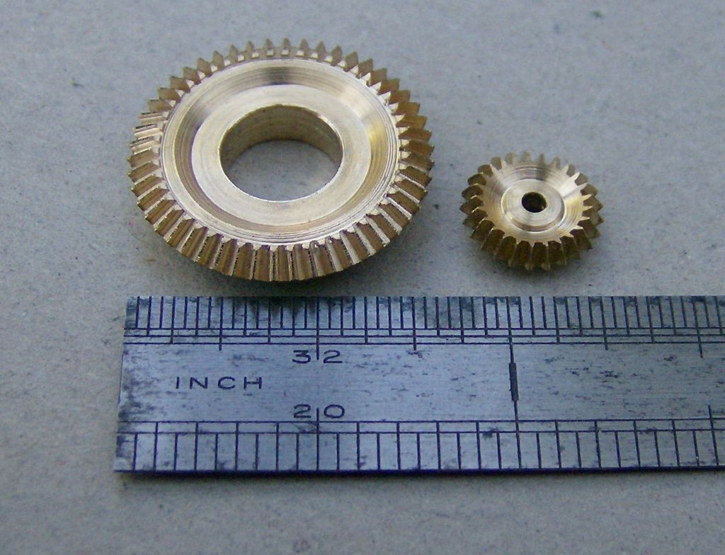
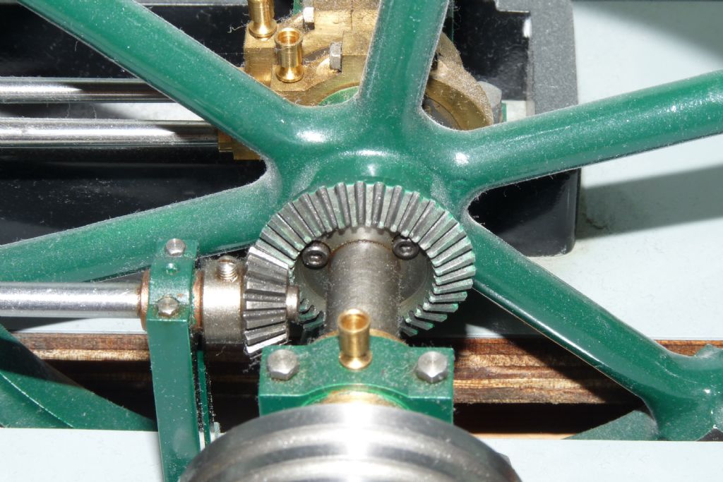
I'm building a 1/8 scale working model of a 1940/50's era mechanical shovel and presently working on the vertical bevel gear
drive to power the whole machine along forward or backwards.
The horizontal bevel is has 22 teeth of 14 DP and a PCD of 1.5714 inch
The verical Bevel is 24 teeth with 14 DP and a PCD of 1.7142
The teeth will be parallel cut and I have been using information gleaned from'Gears & Gear Cutting' by Ivan Law.
Each gears has been set out and drawn as per the text and blanks have been machined ready for cutting teeth. Whoopee!
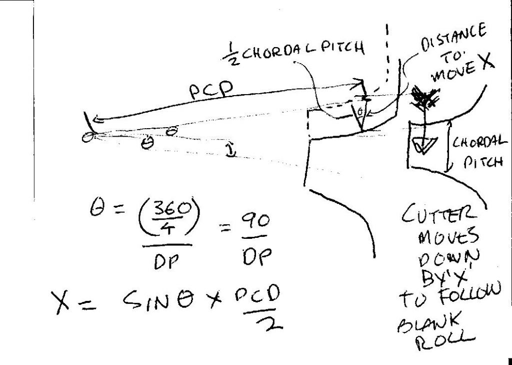
I have a dividing plate with both 22 and 24 holes so the basic cut should not be a problem. I am a little confused with the
calculations on page 106 however for establishing the amount of offset required.
The illustration used is pretty straight forward using a mite gear having 90 degree cone which I assume is waht is
refered to in the following calculation:-
Offset for second cut = 1/2 chordal thickness = 1/2 X PD X SIN 90/20 = 1/2 X 1 X 078 + 0.039
At other points prior to this calculation he refers to SIN 45 = 0.707
My problem is that the 22 tooth gear has a cone angle of 85 Degrees
and the 24 tooth gear a cone angle of 95 Degrees
SINE, TANGENT and COSINE are calculations based on a right angle triangle
so in one sense I cannot use it for my 24 tooth gear.
HOWEVER! When I punch in SIN 85 and SIN 95 on my calculator they both give the same answer of 0.9962
On page 111 left hand column it says : The calculation is always the same and concists of simply multiplying
half the pitch diameter by the sine of the angle, 90/ Number of teeth.
AM I MISSING SOMETING?
Any clarification of the above would be much appreciated.
Geoff Lewis 1.


