Cutting bevel gear wheels

Advert

Cutting bevel gear wheels

Home Forums Beginners questions Cutting bevel gear wheels

Viewing 16 posts - 1 through 16 (of 16 total)
  • Author
    Posts
  • #324798
    Norman Rogers
    Participant
      @normanrogers37749

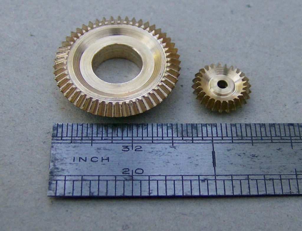
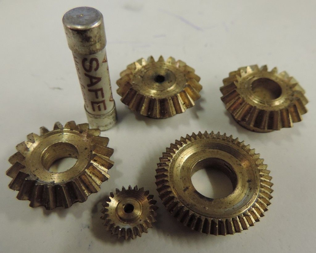
      I’ve reached the point of cutting the compensating gears for the Durham & N Yorks TE in 2” scale as per John Haining’s design in which the main bevel wheels are described as having a Pitch Line Diameter of 5 inches, overall OD 5.018” with 60 teeth of 12DP. Cutting 60 teeth of 12 DP brings the teeth to a point on the inside diameter (circa 3.5 inches) and then goes horribly wrong in the 2nd and 3rd passes. The design as laid out therefore appears contra to the methodology described by Ivan Law, particularly when trying to form the teeth as Ivan’s approach takes the inside/small diameter as the PD and works outwards. First question therefore is has anyone successfully cut the compensating gears as set out in John Haining’s drawings? If they have then I would dearly love to learn where I am going wrong. On a separate but connected note, I have found in my box of possibly useful things a couple of 12DP cutters that have a tooth width more in keeping with 18DP. They are however marked ‘12DP Bevel’. What might be their origins and could/should they be used rather than the standard 12DP involute cutter, although that still leaves the problem of how to correctly do the 2nd and 3rd passes to finish the tooth form?

      Advert
      #8945
      Norman Rogers
      Participant
        @normanrogers37749
        #324803
        Neil Wyatt
        Moderator
          @neilwyatt

          There's a well-known error in Ivan's formula, so it only works for 45-degree bevels.

          I can't find my copy, but basically SIN and COS have got swapped over. As SIN 45 degrees and COS 45 degrees are the same…

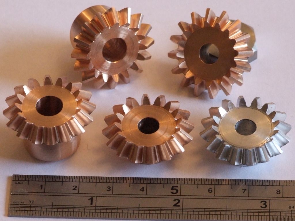
          Get them right and his technique works well. Here's some I prepared earlier:

          #324806
          Neil Wyatt
          Moderator
            @neilwyatt

            I found it: There is one error in his book the calculations on page 106 should use COSINE not SINE. Some more of my gears:

            bevel gears.jpg

            #324808
            Anonymous

              I'm not familiar with the John Haining drawings. However, I have made a number of bevel gears for my traction engines.

              There are two (approximate) methods of cutting bevel gears on a manual milling machine. Straight tooth bevel gears are normally designed using the pitch circle diameter and other parameters at the outer edge of the gear. From your description this is how the John Haining drawings are specified. To cut the bevel gears specified at the outer edge you use an involute cutter of the DP specified at the outer edge. The number of cutter is not directly related to the number of teeth on the gear, but that is not important in this discussion. A standard involute cutter will have the correct tooth curvature, but will be too wide to form the inner tooth shape. So special involute cutters were made for bevel gears. These are the ones in your box labelled "BEVEL". The tooth form will be for a 12DP gear but will be narrower than normal. These are used for the three cuts, the first cut forming the inner shape of the tooth at the correct width, and the second and third cuts widening the outer edge while not affecting the inner edge. This method does not give the correct curvature at the inner edge of the teeth – they will need to be filed, or run-in, to get a good fit. I've used this method once, some 40+ years ago. I think that "BEVEL" involute cutters are no longer commercially available.

              The second approach is the parallel depth method, this is the one described in the Ivan Law book. In this method the gears are designed using the PCD and other parameters at the inner edge of the gear. This means that standard involute cutters can be used. Other than that the three cuts are as for the first method. As implied by the name the depth of the teeth is constant, not varying as in a true bevel gear, but the gears will run perfectly well. I've not used this method, although I have played with the maths when designing the bevel gears for my traction engines.

              For my engines I ignored all the above and modelled the 6DP bevel gears in 3D CAD and machined them on a CNC mill, as I wanted to see if I could produce true bevel gears:
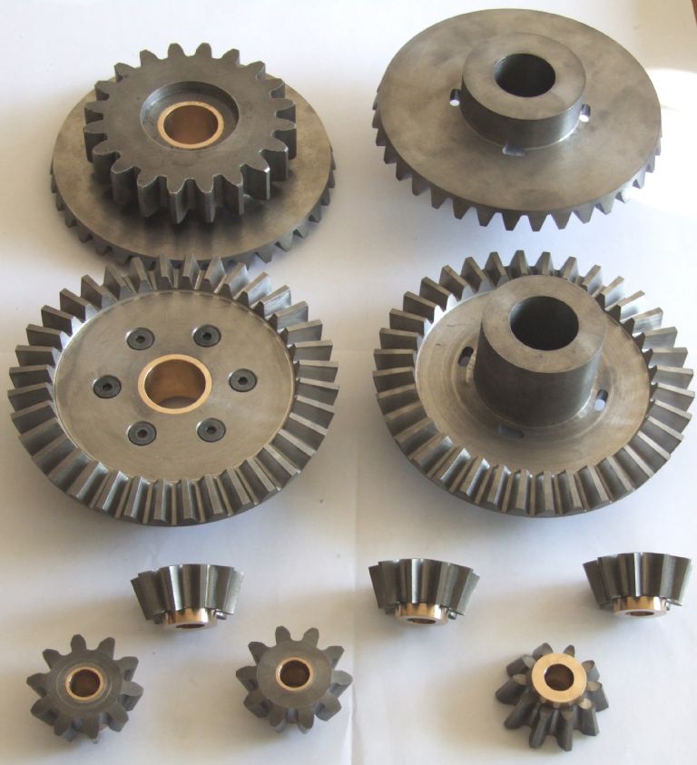
              Cast Iron Gears

              And the 16DP ones I made for the governors:

              governor bevel gears me.jpg

              Andrew

              #324811
              Anonymous

                Additional notes having seen the posts by Neil. One, it was rather unhelpful of Ivan Law to choose mitre gears for his example, as they are a special case. Second, the reason that I didn't in the end make the gears for my engines using the parallel depth method is that by designing using a integer DP at the inner edge you end up with an odd, probably non-integer, number for the DP at the outer edge. If the design has been done using an integer DP at the outer edge (as it appears that John Haining has done, and was for my engines) then it is non-trivial to change to the parallel depth method. You'll probably end up re-designing the whole differential.

                Andrew

                #324815
                Norman Rogers
                Participant
                  @normanrogers37749

                  Hi Neil, I did pick up on that from earlier forum posts, the SIN / COS error influences the calcuations of the OD of the large and small end ….. but all of Ivan's methods for forming the bevel teeth rely on the Pitch Dia employed being at the small end not the large. You can't get 60 teeth of 12 DP on a 3.5" dia yet that is effectively how John Haining drew it and then the 2nd and 3rd cuts are happening inside the PD rather than outside with negative correlations. I can't help thinking the original design is flawed. Calcs suggest that 18 DP would work reasonably well (close but imperfect) but before going there I just wondered if I have overlooked something.

                  #324818
                  Norman Rogers
                  Participant
                    @normanrogers37749

                    Andrew, sorry I missed your post's arrival whilst scribing …. thanks for the additional information around the bevel cutters, the orginal design clearly involves a different approach to the bevel gears. I'll have to do some work to figure out if I can use the bevel cutters as I have them to hand!

                    #324828
                    larry Phelan
                    Participant
                      @larryphelan54019

                      Neil,I could be wrong,but I think you did this before !!!

                      #324831
                      Anonymous

                        Norman: After a bit of a search I've found, and dug out of my archive, the original article by John Haining in Model Engineer describing the D&Y bevel gears. At first glance the design looks fine in terms of DP, tooth numbers and pitch circle diameters. However, I disagree with him on the OD of the gear blanks. I did so on the bevel gear drawings for my engine too.

                        I need to hit the workshop now to machine some parts for work, but later this evening I'll check my OD calculations and also work out what number cutters you need. Off the top of my head, based on my gears, for the 12 tooth pinion you'll need the 12-13 tooth cutter (#8) and for the bevel gear you'll need the 135-rack tooth cutter (#1).

                        Andrew

                        #324902
                        Anonymous

                          I think the basic John Haining design is sound. However, the drawings in the ME article are insufficient to actually make the parts. The critical dimensions are the two pitch circle diameters and how they mate. Sadly none of the dimensions that would be useful for this are listed.

                          As I understand it the design uses 12DP gears with a 12 teeth on the pinion and 60 teeth on the gear. I agree with the article that the PCDs of the pinion and gear are 1" and 5" respectively. However, I make the OD of the pinion 1.1634" and the OD of the gear 5.0327". I've no idea where the values in the article come from, but I think they're wrong.

                          The teeth of a bevel gear are cut with a cutter selected according to the equivalent number of teeth, not the actual number of teeth on the gear. The equivalent number of teeth is the number of actual teeth divided by the cosine of the pitch cone angle. For the pinion the equivalent number of teeth is 12.23 and for the gear 305.94. Based on these numbers we select a #8 cutter for the pinion and a #1 cutter for the gear. I hope these match the bevel gear involute cutters you have!

                          Andrew

                          #324936
                          Norman Rogers
                          Participant
                            @normanrogers37749

                            Thank you for your additional notes. Unfortunately I only have a couple of these bevel gear cutters in the required DP but not #1 or #8 and it seems these are no longer commercially available. I think there's a word for that!

                            #324937
                            JasonB
                            Moderator
                              @jasonb

                              They can be done with standard cutters and don't have to be 100% there are many model traction engines happily trundling around with "as cast" gears and they are certainly not sized to tenths of a thou.

                              #324938
                              Anonymous
                                Posted by JasonB on 02/11/2017 07:41:22:

                                They can be done with standard cutters…………

                                That is simply not true for the gears as designed. If using the parallel depth method then it is the case that standard cutters can be used.

                                As cast gears will probably be fairly close to the correct profile, albeit with a rougher finish. That's not the same as starting with the wrong profile.

                                Andrew

                                #324939
                                JasonB
                                Moderator
                                  @jasonb

                                  Sorry Andrew, I meant bevel gears can be cut with standard cutters but not with what is on the drawings, would need to work out from scratch.

                                  #324976
                                  Anonymous
                                    Posted by JasonB on 02/11/2017 07:57:54:

                                    ……………would need to work out from scratch.

                                    Quite so. Problems arise when one is trying to fit parallel depth gears into an existing design. In order to use standard involute cutters the DP at the inner edge needs to be from a limited range of integers. Inevitably that means the DP at the outer edge will most likely not be integer. Which means that the PCD will not be quite the same as originally designed, which means the supporting structure may need changing. And so on. I looked at using parallel depth bevel gears for my Pickering governors. But in the end decided that it was easier to design and make proper bevel gears than re-design the whole governor, and possibly have to modify the existing casting.

                                    I'm making enough changes to the governor as it is, without changing the bevel gears too. disgust

                                    Andrew

                                  Viewing 16 posts - 1 through 16 (of 16 total)
                                  • Please log in to reply to this topic. Registering is free and easy using the links on the menu at the top of this page.

                                  Advert

                                  Latest Replies

                                  Home Forums Beginners questions Topics

                                  Viewing 25 topics - 1 through 25 (of 25 total)
                                  Viewing 25 topics - 1 through 25 (of 25 total)

                                  View full reply list.

                                  Advert

                                  Newsletter Sign-up