Cross Slide Rotary Encoder

Advert

Cross Slide Rotary Encoder

Home Forums Electronics in the Workshop Cross Slide Rotary Encoder

Viewing 25 posts - 26 through 50 (of 63 total)
  • Author
    Posts
  • #617609
    John Haine
    Participant
      @johnhaine32865

      The encoders that Joe referenced look nice, but would one need to calibrate them? For example, the LS pitch might be a bit off, or the screw somewhat worn.

      Advert
      #617611
      Michael Gilligan
      Participant
        @michaelgilligan61133
        Posted by YouraT on 17/10/2022 17:10:21:

        Not me, although that names are similar

        .

        Oops ! … I thought it was an a.k.a.

        blush MichaelG.

        #617613
        Michael Gilligan
        Participant
          @michaelgilligan61133
          Posted by John Haine on 17/10/2022 17:12:30:

          The encoders that Joe referenced look nice, but would one need to calibrate them? For example, the LS pitch might be a bit off, or the screw somewhat worn.

          .

          Ultimately, direct reading of linear movement must be the preferred option, but if Speedy just wants a convenient display of Metric values this seems very expedient, and almost certainly better than the visual resolution of a Boxford dial.

          MichaelG.

          #617615
          duncan webster 1
          Participant
            @duncanwebster1

            Way back in the mists of time (2013?) I described in ME how I'd mounted an encoder onto the leadscrew of a Cowells lathe. Readout by Arduino. It had a 90 slot wheel which gives better than half a thou resolution with a 0.1" pitch screw. You'd need to find a way of mounting the optoswitches onto the handwheel bracket. By this time, I'd be seriously looking at just buying the gubbins and using a magnetic tape. You'll want DRO on the saddle soon enough having got used to it on the cross slide. If you want a copy of the article send me a pm

            #617628
            Mike Poole
            Participant
              @mikepoole82104

              Chronos list these displays for the C3 type lathes. You may be stuck with the feedscrew pitch of the C3 lathe though.**LINK**

              Mike

              #617634
              Speedy Builder5
              Participant
                @speedybuilder5

                I guess I was looking for something like this with a hole through the middle?

                #617635
                Michael Gilligan
                Participant
                  @michaelgilligan61133
                  Posted by Speedy Builder5 on 17/10/2022 19:31:53:

                  I guess I was looking for something like this with a hole through the middle?

                  .

                  That was certainly my assumption

                  … and what Mike links 

                  MichaelG.

                  Edited By Michael Gilligan on 17/10/2022 19:50:40

                  #617636
                  JasonB
                  Moderator
                    @jasonb

                    They do have a hole through the middle see here

                    However as I said in my first post I think they come set up for metric screws so one turn will read 2.00mm or 0.079" on the display

                    #617639
                    AJAX
                    Participant
                      @ajax

                      Why not just fix a dial indicator to the cross slide to show movement across the bed? Cheap, no battery, easy to read and zero.

                      #617658
                      Speedy Builder5
                      Participant
                        @speedybuilder5

                        Fair point Ajax! The CHRONOS readout is the sort of thing I was looking for, like Jason said, if I could change the pitch of the feed screw on the device.

                        Bob

                        #617660
                        Michael Gilligan
                        Participant
                          @michaelgilligan61133
                          Posted by Speedy Builder5 on 18/10/2022 06:48:07:

                          […] like Jason said, if I could change the pitch of the feed screw on the device.

                          .

                          That’s why I said this style of read-out had disappeared by ‘natural selection’ [Darwinism]

                          I have never looked inside the SIEG device, but I suspect it is very similar to the WolfCraft one.

                          That simply didn’t have enough ‘native resolution’ to cope as a data-source for Imperial/Metric conversion.

                          Sorry, I no longer have the device, so I can’t take photos … but it was mechanically quite crude.

                          MichaelG.

                          .

                          Edit: __ See here for the use of Gray Code on shafts:

                           https://en.wikipedia.org/wiki/Gray_code#Position_encoders

                          If I recall correctly the WolfCraft device only used four tracks

                          [as per the monochrome illustration on that page]

                          Edited By Michael Gilligan on 18/10/2022 07:54:48

                          #617662
                          Michael Gilligan
                          Participant
                            @michaelgilligan61133

                            This [being a more sophisticated SIEG unit] is interesting: **LINK**

                            http://www.mini-lathe.com/mini_lathe/reviews/Sieg_DRO/dro2.htm

                            MichaelG.

                            Edited By Michael Gilligan on 18/10/2022 08:10:25

                            #617665
                            JasonB
                            Moderator
                              @jasonb

                              Thanks for the last link Michael, I knew they were thread specific but thought it was the metric thread.

                              What's really needed is something like a bike computer where you set distance according to tyre diameter but in this case it would be thread pitch. Switching between radius and diameter reading would be an added bonus.

                              #617668
                              Michael Gilligan
                              Participant
                                @michaelgilligan61133

                                Just spotted this offering by ARC : **LINK**

                                https://www.arceurotrade.co.uk/Catalogue/Machine-Spares/SC3-Mini-Lathe-Spares/SIEG-Mini-Lathe-DRCD-to-Manual-Conversion-Kit

                                It would be interesting to know what has driven this

                                MichaelG.

                                #617673
                                JasonB
                                Moderator
                                  @jasonb

                                  That will be the same one I linked to about this time yesterdaywink

                                  #617675
                                  Michael Gilligan
                                  Participant
                                    @michaelgilligan61133
                                    Posted by JasonB on 18/10/2022 10:05:05:

                                    That will be the same one I linked to about this time yesterdaywink

                                    .

                                    Apologies, Jason … I don’t recollect following your link [because I wrongly assumed it would be for a ‘digital upgrade’ not for an upgrade from digital to mechanical]

                                    mea culpa

                                    MichaelG.

                                    .

                                    P.S. __ I now also note that the SIEG digital unit, that it is shown as replacing, is already the more sophisticated version [!]

                                    Edited By Michael Gilligan on 18/10/2022 10:32:26

                                    #617680
                                    JasonB
                                    Moderator
                                      @jasonb

                                      A little birdie tells me they use a disc that is encoded for a specific thread pitch.

                                      Prone to problems with cold temperatures as well as ingress of swarf and coolant that caused unacceptable number of failures, new version thought to be equally as prone to problems.

                                      #617686
                                      Michael Gilligan
                                      Participant
                                        @michaelgilligan61133

                                        Thanks yes

                                        #622645
                                        Speedy Builder5
                                        Participant
                                          @speedybuilder5

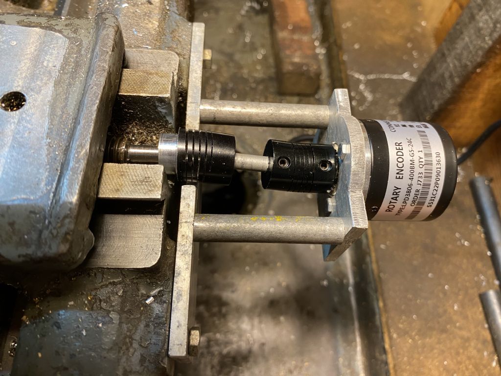
                                          Finally got there. Using an Arduino and Encoder, a couple of in line flexible joints and now can read out to 0.0001". A bit of a tight squeeze into the aluminium box and at first noise between the encoder cable and general electrical noise. We seem to have a stable and repeatable system by Screening the Encoder cable attached to the metal box and encoder "grounded" to the lathe.

                                          The switches are On/Off  Reset  and choose of Radius or Diameter setting (Not sure if I would ever need Diameter !!)

                                          crossslidedro 1.jpg

                                          crossslidedro 2.jpg

                                          Edited By Speedy Builder5 on 25/11/2022 16:46:06

                                          #622649
                                          Ian P
                                          Participant
                                            @ianp
                                            Posted by Speedy Builder5 on 25/11/2022 16:44:09:

                                            Finally got there. Using an Arduino and Encoder, a couple of in line flexible joints and now can read out to 0.0001". A bit of a tight squeeze into the aluminium box and at first noise between the encoder cable and general electrical noise. We seem to have a stable and repeatable system by Screening the Encoder cable attached to the metal box and encoder "grounded" to the lathe.

                                            The switches are On/Off Reset and choose of Radius or Diameter setting (Not sure if I would ever need Diameter !!)

                                            Edited By Speedy Builder5 on 25/11/2022 16:46:06

                                            Look like a couple of 'out of line' inline couplings!wink

                                            Ian P

                                            #622654
                                            bernard towers
                                            Participant
                                              @bernardtowers37738

                                              So if your couplings are out of line how can your measurements be ok to .0001 at all points of rotation?. Wouldn't it be better if the encoder was directly in line with the feed screw ?.

                                              #622659
                                              SillyOldDuffer
                                              Moderator
                                                @sillyoldduffer

                                                I like it except the measurement is of screw turns rather than tool movement and is thus vulnerable to backlash error.

                                                The Arduino could be programmed to compensate but would need to be recalibrated periodically as the nut and screw wear. Which reminds me, the amount of backlash on my lathe has crept up enough to annoy me again. There is no rest for the wicked…

                                                Dave

                                                #622689
                                                Les Riley
                                                Participant
                                                  @lesriley75593

                                                  I had been meaning to fit some sort of reader to my Myford for many years. However, as above, I didn't want a bulky slide in the way.

                                                  At the Midland Exhibition in 2019, I saw the DRO stand with the magnetic strip fitted under the cross slide. Perfect.

                                                  Completely hidden and no backlash problem. All the old lash-ups devised over the years are history.

                                                  #622700
                                                  Speedy Builder5
                                                  Participant
                                                    @speedybuilder5

                                                    I don't know where my reply went to Bernard, but the reason for the offset is that the cross slide would foul the encoder as it reaches full travel. I had a quick scout around to see what the angular error might be, but didn't find anything on the net.

                                                    Dave, I could live with that probably no worse than the divisions on the cross slide handle Its been an interesting exercise in rattling the grey cells.

                                                    Bob

                                                    #622710
                                                    Ian P
                                                    Participant
                                                      @ianp

                                                      Without dimensions or knowing what lathe this is it is hard to offer an opinion or make judgement on the arrangement, however from the picture it looks as if the cross slide will be well out of its dovetail engagement by the time it gets anywhere near the encoder body diameter.

                                                      At full travel does the cross slide pass over the encoder?

                                                      To minimise angular accereration errors in (pairs of) Hooke (and I presume beam type) couplings, the input and output shafts need to be parallel but also the 'phasing' of the two couplings has to be correct. On a Hooke joint the pivot points are obvious but on the helical coupling it would be a bit more difficult to define just where the beam starts.

                                                      Ian P

                                                    Viewing 25 posts - 26 through 50 (of 63 total)
                                                    • Please log in to reply to this topic. Registering is free and easy using the links on the menu at the top of this page.

                                                    Advert

                                                    Latest Replies

                                                    Viewing 25 topics - 1 through 25 (of 25 total)
                                                    Viewing 25 topics - 1 through 25 (of 25 total)

                                                    View full reply list.

                                                    Advert

                                                    Newsletter Sign-up