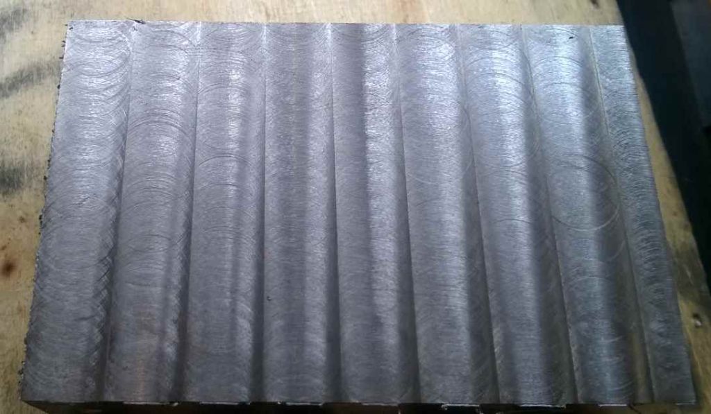
Crop Circles – poor surface when milling

Advert

Crop Circles – poor surface when milling

Home Forums Beginners questions Crop Circles – poor surface when milling

Viewing 25 posts - 26 through 50 (of 51 total)
  • Author
    Posts
  • #241570
    mechman48
    Participant
      @mechman48

      Along with all the other replies I would suggest that you tram the mill; it looks as though there is a trailing edge on the cutter, it only takes an ever so slight out of true on your mil head to produce those types of marking.

      George.

      Advert
      #241571
      julian atkins
      Participant
        @julianatkins58923

        As is often the case on here a most illuminating and instructive discussion.

        Lock the head.

        Use the correct cutter for the job.

        Other ME type solutions such as fly cutting may give a better finish at far less cost in tooling but takes longer.

        Get to know your Mill !

        Cheers,

        Julian

        #241595
        Neil Wyatt
        Moderator
          @neilwyatt

          > as far as fly cutting is concerned, this is a weak and small machine. my one attempt at flycutting mainly had the effect of wearing the cutter flat.

          Like the slitting saw thread, fly cutters need to run slowly, about 100rpm for a 3" diameter cut or they will blunt very fast.

          Neil

          #241604
          MW
          Participant
            @mw27036
            Posted by Iain Downs on 04/06/2016 20:14:17:

            I'm not entirely sure what 'chip welding' is, however google seems to think that a cure with carbide is to speed up. This piece was done at 1000rpm and the other pictures at 2000 rpm. However a previous run at 2K cutting along the X axis was not this bad.


            Chip welding is chiefly a concern with aluminium where the material chips and "sticks" to the edge of the tool and can build up, it can lead to overworking the motor and a poor finish because the machine has to work harder to compensate for the artificially "dulled" cutting edge caused by the build up. The good news is it actually prolongs the life of the tool itself as the chips take most of the punishment.

            That being said, it's generally considered far from desirable result and alot of special tools are sold for the "production" cnc machining of aluminium, especially to allow the chips to break off and away from the tool rather than dig in and build up onto it, it's also why alot of cnc machinists prefer flood coolant with aluminium primarily to allow chips to be washed away rather than for the cooling effect on the tool itself.

            Other steel alloys could also be a problem for chip welding but from the steels i've used mainly EN3B, EN1A and silver steel, i can't say i've seen it happen.

            Brass definitely doesn't but copper and gunmetal might be prone to it. With aluminium you can almost expect it to do so without any preventative measures. Some plastics are known to be prone to chip welding too, peck feeding whilst drilling plastics tends to be the order of the day to prevent "melting" inside the bore and poor finish. 

            But basically if it is chip welding, you would've definitely seen it, because its on the tool! 😛

            Michael W

            Edited By Michael Walters on 06/06/2016 11:13:07

            Edited By Michael Walters on 06/06/2016 11:15:51

            #241605
            Martin Kyte
            Participant
              @martinkyte99762

              Hi Ian

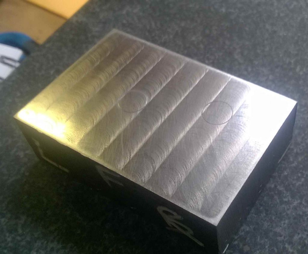
              Just had a look at your initial photos and I would say that the cutter is not presenting perpendicular to the work. Further I suspect it is cutting lower on the trailing edge which would tend to force the cutter away from the work slightly and generate the ridges as you see. When you stop the travel the cutter then cuts to depth and generates a circle. Firstly try cutting in the opposite direction so that the cutter cuts deepest on the front lip. The circles should disappear. This tells you that the head is not vertical and that gives a preferential direction of cut. Tram the head.

              The situation is made more complex by your statement that the gibs are not set correctly. However as you say you have adjusted them and the situation is improved but not corrected I think the problem is as I have suggested.

              My other comment would be that skimming cuts don't work too well unless you have a really sharp cutter.

              regards Martin

              #241620
              Anonymous

                It's odd that the surface finish in the 'crop' circles seems to be much better than the rest of the surface. So I would surmise that the problem is not to do with mill not being trammed, although that may have other downsides. It is more likely to do with the fundamental cutting process. It is as if the cutter is cutting properly within the circles but not elsewhere?

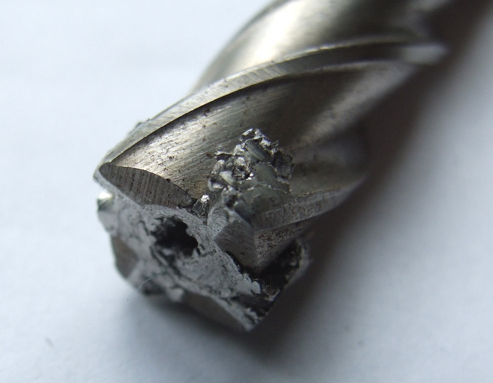
                This is what happens to a milling cutter when you get chip welding:

                clogged cutter.jpg

                I've only ever experienced chip welding on aluminium, never had a problem with plastic, provided you don't melt the material. smile o Fairly high chip loads seem to help. When turning chip welding results in a poor finish. When milling it clogs the cutter flutes and it you don't do something about it pronto the cutter will snap. Climb milling results in a much better finish on aluminium, but the reverse is true on plastics.

                I generally turn and manually mill aluminium dry, as coolant being sprayed everywhere is a PITA to clean up. However, sometimes a squirt of WD40 can help when deep drilling. For CNC milling of aluminium I use flood coolant, to alleviate chip welding as said, and to wash the swarf away to prevent re-cutting.

                Andrew

                #241621
                Ajohnw
                Participant
                  @ajohnw51620

                  The other answer is to reduce the cutter speed so that it doesn't melt the aluminium. Sharp cutters make a huge difference as well. The flutes on the side should ideally be sharp enough to cut fingers on. To be honest I have only come across cutters that have been reground at work that will cut fingers easily but new ones are sharp and as soon as the edge wears they either need throwing away or resharpening. Just cleaning up the end wont help. Neil's sharp solid carbide cutters probably help in this respect. On hss the grade ideally needs to be one of the high cobalt onesas they will last longer however it's high loading capability red hot wont help machine aluminium. When the term red hot is used in this respect it juts means the extreme cutting edge of the tool.

                  John

                  #241673
                  Iain Downs
                  Participant
                    @iaindowns78295

                    Hi, All.

                    I don't think this is chip welding (but thanks for the description, Michael!). I'm on steel not aluminium with a new carbide cutter and by touch (I've not taken it out of the collet, yet) the edges seem clear and sharp.

                    I have seen this turning aluminium and my original carbide tipped tools have sometimes built up a coating of aluminium on the sharp edge. This doesn't seem to happen with my home ground steel tools.

                    I will do some more investigation (mucking about) later – probably at the weekend. Sadly the day job and family are calling this week so I doubt I will get an escape opportunity until the weekend.

                    I will keep you posted!

                    Iain

                    #241685
                    Anonymous
                      Posted by Iain Downs on 06/06/2016 19:12:19:

                      I don't think this is chip welding……………..

                      Quite so. Another question, what is the exact material, all steel is not created equal?

                      Andrew

                      #241722
                      Iain Downs
                      Participant
                        @iaindowns78295

                        I snuck out.

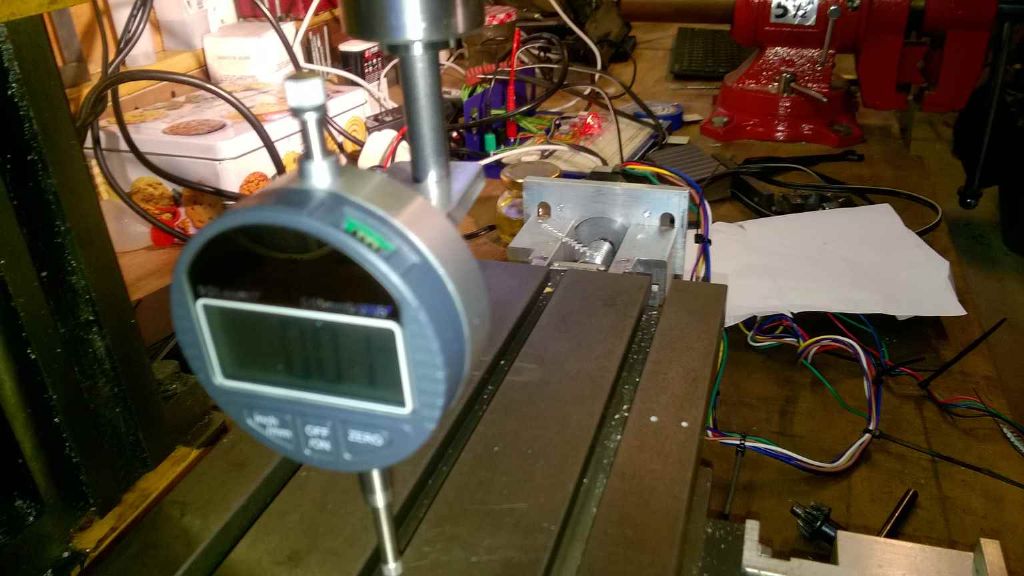
                        I setup a dial indicator on a stalk attached to a 10 mm rod held in a collet.

                        tramming setup.jpg

                        I swept the indicator round to the 8 cardinal points (more or less – I wasn't bothered about millimetric accuracy).

                        tramming.jpg

                        The diameter of the circle is about 12cm and as you can see, left right it's as good as it's going to get. Front back it's about 0.24 mm out with the front of the circle higher than the back (a bigger gap) – the spindle/riser is leaning back.

                        When I measure the fall of the table (by moving the table), I see around 0.13 mm fall over the same distance.

                        So if I corrected the table fall with a shim or scraping the rear way, the tramming would be something like 0.11 mm out front to back (over 120mm).

                        So to fix this I would need to shim the *back* of the riser up by around 0.05mm (2 thou), assuming that the block is about 60mm front to back (not measured this – I'm just trying to establish the principle.

                        Does this make sense? Should I shim or scrape? Frankly, both seem a tad challenging. Where can I get fractional though shims? My feeler gauges go 0.05, 0.10 and so on.

                        Do I really want to scrape this (or the ways…).and are there any tutorials / videos?

                        Also this implies that there will be around a 0.01 rise from the back of the cutter (10mm) to the front which is likely enough to explain the pattern on the 'good' cut.

                        Oh – Andrew, the steel is EN32B from M Machine Metals.

                        Iain

                        #241725
                        Frances IoM
                        Participant
                          @francesiom58905

                          have you removed the column to see if there is paint where it shouldn’t be between column + base ?

                          #241738
                          Iain Downs
                          Participant
                            @iaindowns78295

                            That would be a nice solution, wouldn't it?

                            I shall look at that when I have a chance.


                            Iain

                            Edited By Iain Downs on 07/06/2016 07:49:14

                            #241744
                            john carruthers
                            Participant
                              @johncarruthers46255

                              A mate has a similar machine he aqcuired from a school sell off.
                              It sort of worked when he got it but had similar problems getting the column orthogonal to the table.
                              He could get it right when static but any load on the quill tipped the column back a tad.
                              We shimmed it, one thickness of coke can and one of 'pie dish' ally foil under the column bracket was sufficient to give a decent finish.

                              #241748
                              Vic
                              Participant
                                @vic
                                Posted by john carruthers on 07/06/2016 08:39:22:

                                A mate has a similar machine he aqcuired from a school sell off.
                                It sort of worked when he got it but had similar problems getting the column orthogonal to the table.
                                He could get it right when static but any load on the quill tipped the column back a tad.
                                We shimmed it, one thickness of coke can and one of 'pie dish' ally foil under the column bracket was sufficient to give a decent finish.

                                "Pie dish ally" I'll have to remember that one! smiley

                                #241865
                                Iain Downs
                                Participant
                                  @iaindowns78295

                                  Yes – I noticed that gently leaning on the machine could shift the dial reading by quarter to have a mm or more.

                                  Iain

                                  #241870
                                  Ajohnw
                                  Participant
                                    @ajohnw51620

                                    What machine is it ?

                                    If a gentle lean produced that much movement I would wonder what is under the column and if the bolts were tight.

                                    John

                                    #241894
                                    Iain Downs
                                    Participant
                                      @iaindowns78295

                                      CMD10 – a Seig X1 I believe. It's a tiny thing.

                                      To get 0.5mm deflection was a pretty solid lean I must admit.

                                      The column was bolted down tight enough.

                                      Since then I've had a play at tramming it. I've pushed a 0.10 shim (feeler gauge) under the front way and that's leveled the table withing 0.01 mm. I've not tried moving the table in the X direction yet, so I'm not sure if it will stay in place. I also have a feeling that feeler gauge isn't the most professional way to do this.

                                      I've also tilted the head by shimming under the front of the column. I thought I'd about got the right lean with .08 mm (or more likely 3 thou – it's an old feeler gauge and the writings worn off), but that's a bit over (after the 0.10 shim went in), so I'll try and find a .05mm feeler and use that.

                                      It's rather less frightening than I thought, though no scraping has been involved and no milling has yet taken place!

                                      Iain

                                      #242430
                                      Iain Downs
                                      Participant
                                        @iaindowns78295

                                        So, I'm now more confused.

                                        To recap, I'm trying to tram the mill in order to get a good finish and an accurate cut (I want to be able to make parallel sides!).

                                        I believe that the mill table slopes downwards to the front and I've found (surprise) that the column's a bit tilted.

                                        I put a 0.1mm feeler gauge under the front way which made the table level within 0.01mm front to back. by dint of bits and bobs of feeler gauge I got the spindle square on to within a tad over a though over a circle with a 105 mm diameter – pretty close to flat front to back and a fall of .04mm on the left.. Which I thought was quite good for a micro mill. I've nothing in the half though region which is what I'd have needed to tune it up more.

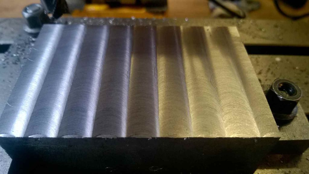
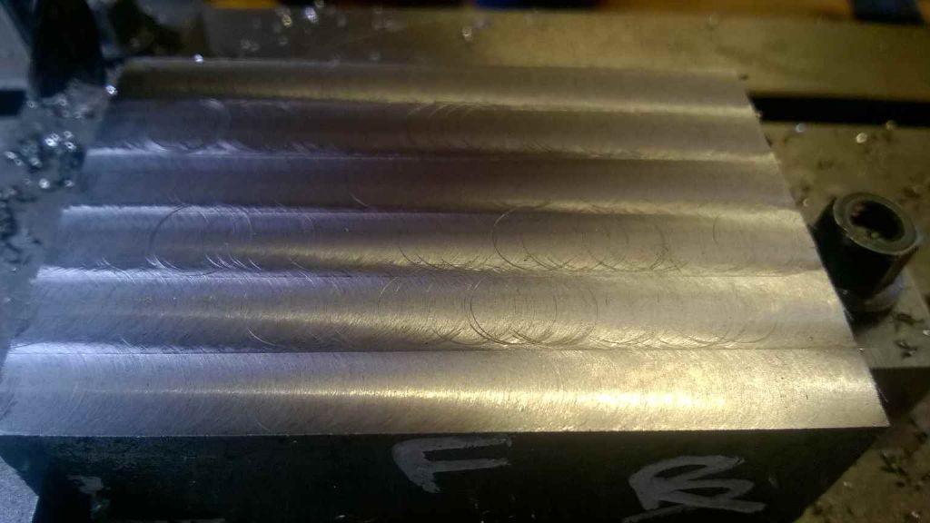
                                        Then mounted my test block and faced it. 10mm carbide cutter, approx 0.1 depth of cut, 2000rpm and around 4mm / sec feed.

                                        tramming after good setup xy.jpg

                                        Although the picture looks a bit imperfect I was quite pleased. The metal feels smooth with the ridges in the front back direction barely discernable by touch. a dial indicator gives a tick of about .003 / .004 mm when it runs over them. The piece (50mm x 80mm) was level across the short face, but rose about .07 mm to the right, which is more or less consistent with the tramming results

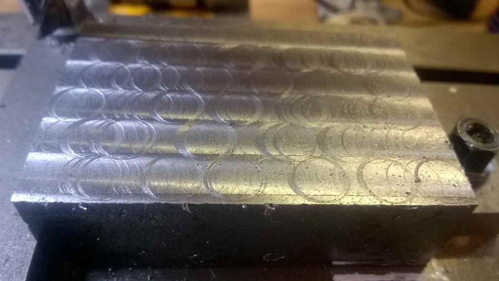
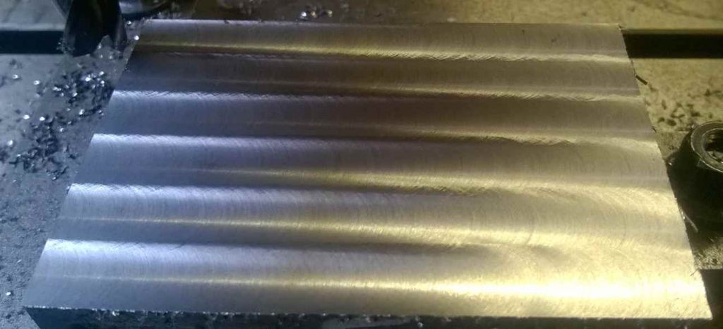
                                        Then i tried the same cut (0.1 mm) in the other direction. This was a disaster!

                                        tramming after good setup yx.jpg

                                        Before I panicked entirely, I re-did the face with the original direction and got the good results I had the first time,

                                        I 'lapped' it with some 800 abrasive paper on my surface table which removed any visible tick for the ridges. though they are still visible – I ran out of paper before finishing.

                                        tramming second yx after lapping a bit.jpg

                                        Now this is where things get wierd. I was going to try and remove the .03 mm tramming error. I replace the dial indicator arrangement and re-checked the tramming. Now it appeared to be out on the left by .03 mm but in the opposite direction.

                                        I thought, 'perhaps its where abouts it is on the table' so I moved the table to the far left (reading on right of table) and took a reading.

                                        Somewhat to my surprise the table now falls ,2mm to the front and falls .08mm on the left. And this is now consistent. I've moved the table all the way to the left and at all points inbetween I can the same reading (~0.2 and 0.08 mm out), Th table now falls by about 0.03 which is worse than before the movement.

                                        I do have a theory for all of this which I wanted to pose to the experts! I think the issue is around the 0.1mm feeler gauge under the ways which I'm using to raise the table. I think that the way is not running smoothly on it which is why the left right cut is so poor. And I think it's moved around a bit which is why the tramming's gone out.

                                        How should I properly level the table? I would guess I would either have to get a better shim, or scrape or lap the far way.

                                        I'd appreciate any practical advice on how to accomplish any of these tasks!

                                        Iain

                                        (P.S. Sorry this is so long!)

                                        #242432
                                        Ajohnw
                                        Participant
                                          @ajohnw51620

                                          Are your slides tight ? When I bought a Chinese miller I ruled that one out completely just by looking at it.

                                          Anyway on any machine that has relatively low mass compared with cutting forces the slides need to be set pretty firmly. It's not easy to do on the head because the weight and the position of the parts tilt the whole thing if there is any play in the slides at all. The best way to do the bed is the same as on lathe cross and compound slides – take the lead screw out and push by hand and adjust for some resistance to movement. On a miller I usually do it via the feed handle and adjust for some definite resistance when it's turned. Getting the head right isn't easy. Maybe try locking it dead solid and then releasing them a touch but even on lathes only tiny turns of the grub screws are needed.

                                          The only thing I can add is that it's a good idea to get some decent oil on the slides first and if pushing by hand to fast the oil will break down and the slide will tend to grab.

                                          I might expect to have to do this adjustment several times before it's as good as it can be.

                                          Just add but it's hard to explain. Say I had locked a slide dead tight via the gib strip grub screws. I'd release them one at a time and then retighten  being very careful about how much torque I applied. I usually find this needs doing again after things have settled down and having done it several times have a fair idea how much torque to apply when they are loosened and retightened. It's more like ajusting so that they are  touching the gib strip with a tiny amount of pressure. On the bed this is likely to need to be done in sections so isn't so easy.

                                          John

                                          Edited By Ajohnw on 12/06/2016 11:52:45

                                          #242438
                                          Anonymous
                                            Posted by Iain Downs on 12/06/2016 11:29:26:

                                            I'd appreciate any practical advice on how to accomplish any of these tasks!

                                            Iain: I'm afraid you're approaching this the wrong way round. Something is still amiss with the basic cutting process, at least in the X direction. The fact that the table/column might be misaligned is irrelevant. Until you get the cutting process sorted there is no point in trying to align the various parts of the mill; you'll just end up chasing your tail.

                                            If I recall correctly you said that the material was EN32B – a low carbon case hardening steel. I have used this to make a pair of case hardened bevel gears. I don't recall any problems machining it; but it was 40 years ago and on a horizontal mill that weighed several tons. So not really relevant. However, EN32B is very similar to EN3B and hot rolled steel, which can be tricky to machine as they 'tear' if parameters are not right. Contrary to popular opinion you don't need a razor sharp cutter, but you do need a decent chip load. Personally for trial cuts I'd try a larger DOC, say 0.5mm. I think you were running at 2000rpm? If so I'd use a feedrate of at least 400mm/min assuming a 4 flute cutter.

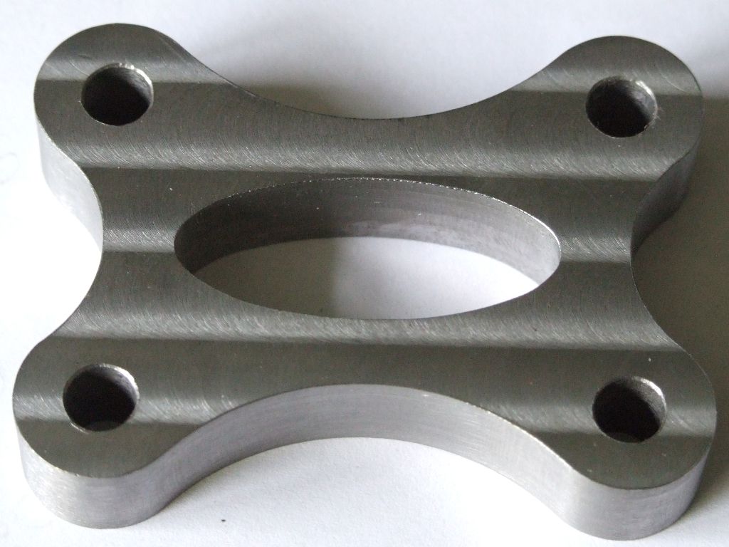
                                            This part was made from hot rolled steel:

                                            water pump spacer.jpg

                                            I have a different mill, but otherwise the setup was similar; a well used 3 flute carbide cutter running dry at 2000rpm and 500mm/min. Close inspection will show the odd hint of a 'crop circle' (see top right), possibly due to entrapped swarf.

                                            Once you have cutting process sorted then you can worry about any larger scale misalignment of the mill. My experience of this sort of thing is that it is very easy to get mislead by measurements and you end up going round in circles, pun not intended. embarrassed So I tend to leave things well alone until I am sure that what I am seeing is real.

                                            Andrew

                                            #242446
                                            JasonB
                                            Moderator
                                              @jasonb

                                              Ian, when you did the front to back cuts did you lock the side to side movement for each pass. Same for the side to side cuts, did you lock teh front to back between cuts.

                                              If so it could suggest you have a lot of play in the sideways direction due to play in the ways. With your front to back way locked put teh dti on the table and then see if you can move it up and down.

                                              The fact you get a good finish one way can rule out spindle play and cutter/depth of cut to some extent.

                                              #242472
                                              Neil Wyatt
                                              Moderator
                                                @neilwyatt

                                                I think the bit of feeler gauge was suggested as a way of proving an error, rather than as a long-term solution?

                                                Neil

                                                #242482
                                                Frances IoM
                                                Participant
                                                  @francesiom58905

                                                  have you looked at the gib strips – on one such machine I found the gib to be banana shaped – very difficult to allow smooth movement over any significant length being either too loose at one point or too tight at another depending on adjustments

                                                  #242487
                                                  Iain Downs
                                                  Participant
                                                    @iaindowns78295

                                                    So. I've stripped the mill down and checked and re-assembled. I've found that there is a high spot on the Y axis way (in / out)which explains the binding I've found when adjusting the Y jibs and the way on the back of the table is 0.08 or so higher than the front one.which explains the drop.

                                                    I've put the machine back together without the 0.1mm feeler gauge.

                                                    I set the jibs so that they ran smoothly (pushed by hand – no leadscrew connected), but 5 degrees tighter on any jib screw bound them.

                                                    Here is the result

                                                    after rebuild 2mm per sec.jpg

                                                    Not great. So I decided to do the opposite of some of the advice here and I slowed the cut down from 2mm/sec to 1mm / sec (60mm/min). With this as the result.

                                                    after rebuild 1 mm per sec.jpg

                                                    I was rather happy with that. It's actually better than the photo makes it look.

                                                    Finally I tried the other Axis. This is the one which was better before. Not now!

                                                    after rebuild 1 mm per sec yx.jpg

                                                    It's not quite as ragged as it looks (the left hand edge was started at 2mm ./ sec which is why it's a mess).

                                                    The Y axis (this one) is driven my a NEMA 17 motor which is struggling at the higher speeds (8 mm / sec for non-cutting moves).

                                                    I'm also wondering if part of the problem is the way I'm driving the motors. I'm using the 'loop' in the Arduino which may be resulting in some uneven pulses. I may try driving the motor timing from a timer not under a software loop.

                                                    I'm still keen to understand what the best way of tuning up the table is. I would almost certainly try and scrape the middle bit of the table – the ways on the table proper are not really accessable due to the dovetail.

                                                    Iain

                                                    #242501
                                                    Neil Lickfold
                                                    Participant
                                                      @neillickfold44316

                                                      If you have enough coolant flow or compressed air with oil mist, most of your issues will vanish. I have found that if the material is a little gummy , it can stick to a cutter somewhere and leave these types of marks on the work piece.It can also happen to fly cutting as well if the cutter gets a build up on the cutting edge. Again usually with what I call gummy type of materials. Having a polished surface on the top cutting surface helps with a home made fly cutter.

                                                      Neil

                                                    Viewing 25 posts - 26 through 50 (of 51 total)
                                                    • Please log in to reply to this topic. Registering is free and easy using the links on the menu at the top of this page.

                                                    Advert

                                                    Latest Replies

                                                    Home Forums Beginners questions Topics

                                                    Viewing 25 topics - 1 through 25 (of 25 total)
                                                    Viewing 25 topics - 1 through 25 (of 25 total)

                                                    View full reply list.

                                                    Advert

                                                    Newsletter Sign-up