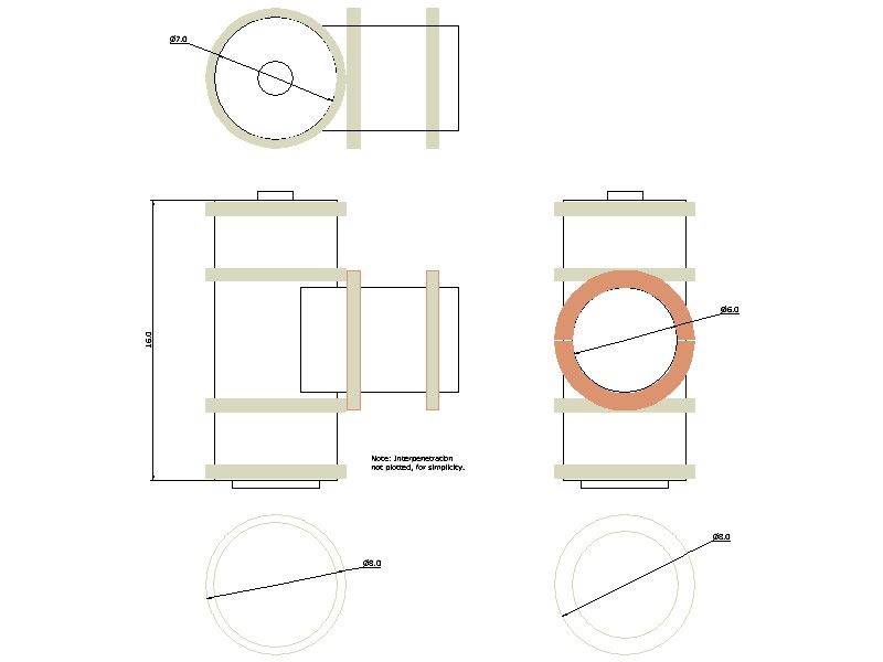
I have the approaching problem of lagging a boiler whose shape is essentially a Tee-piece standing on one arm of the T. As the drawing below shows.
Outer firebox: 7" o.d., 16" high.
Horizontal barrel: 6" od X about 6" from front of firebox to rear of smokebox.
Smokebox 8" dia over an inset, steel channel ring that steps the bore down to the barrel.
Option to fit a superheater with bulkhead fittings for them (plugged for now) and the blower through the channel.
Important: Working temperature, ~ 200ºC.
.
O.d. of cladding: 8 – 8.25 inch, for both, so only half-inch deep insulation on the firebox ( model locos seem to use much less) but nearly an inch on the barrel – to hide the big step in radius as much as for insulation.
The insulation and cladding-sheets split longitudinally into halves to be able to fit or remove them without dismantling half the vehicle. (I'll not be let in the SMMT if I design a vehicle an owner can service easily!)
.
So: what material for the crinolines….
My thoughts are:
– Rings made from exterior-grade 12mm plywood,
– Rings made in 2 or 3-ply form, from 8 or 12 softwood segments per layer, overlapped joints (like brickwork bonding); held together with adhesive and small, preferably stainless-, steel screws.
– Metal bands rolled and countersunk-screwed to wood or SRBF spacers, cut e.g. from large-diameter dowel. (I think locomotive boilers use something like that.)
Wooden parts soaked in preservative after manufacture. The rings would be only 1/2" thick on the firebox, so not ever so strong.
– Some form of rigid heat-insulating board. I am not sure what is available – I know a gas-fitter who could probably tell me – but I suspect these would be very fragile and might even break in their manufacture.
Obviously I'd need accommodate the blower and (if fitted) superheater pipes under the lagging, so the rings may need interruptions fitted with small cover-plates.
The superheater would use 10mm / 3/2" pipe from the regulator on the firebox top, forwards to the smokebox then back to the engine's inlet, which is just behind the boiler and about level with the regulator. The original had no superheater, just a direct but bare iron pipe to cool the steam before it reached the valve-chest.
.
Any ideas, thoughts, pit-falls I have not spotted, please?
.
Outline drawing: crinolines coloured. (drawn using TurboCAD 2021).
True interpenetration shape omitted for simplicity: not necessary for this, and anyway it takes a lot of plotting!)

Edited By Nigel Graham 2 on 01/01/2023 13:38:14
Nigel Graham 2.


