Creating your own scale drawings

Advert

Creating your own scale drawings

Home Forums CAD – Technical drawing & design Creating your own scale drawings

Viewing 13 posts - 1 through 13 (of 13 total)
  • Author
    Posts
  • #521374
    Buffer
    Participant
      @buffer

      Does anyone have any good advice on creating your own scale drawings of complex projects from pictures of the original and full size drawings? I'm trying to do this for a piece of artillery and it's so hard. As an example everything ends up as decimal inches and not the fractions you normally see. Nothing just matches up with available sections. Do you just modify your bits to fit what you can get and no one notices? Should you just make bits that look and feel right rather than are absolutely to scale?

      I have been tinkering with fusion and solidworks but to be honest when copying an original its pretty hard to model parts unless you have a drawing to work from which is a bit of a catch 22.

      I'm sure a lot of you will have done this sort of work and I would really appreciate any advice you have to offer.

      Many Thanks

      Advert
      #21334
      Buffer
      Participant
        @buffer
        #521385
        Paul Lousick
        Participant
          @paullousick59116

          Hi Buffer,

          "everything ends up as decimal inches and not the fractions you normally see. Nothing just matches up with available sections" This is what normally happens when you scale from full size and dimensions have to be substituted for what is available. If you scale a dimension, originally shown as a fraction, you will get a very small fraction, so better to use decimals.

          You can make a CAD model, using the original full size dimensions and then apply a scale factor prior to creating the drawings. The problem with this method is that the dimensions will only be a scale version of the original. Not whole numbers and will not match available plate thicknesses, diameters, etc.

          Solidworks can display dimensions as fractions in drawings. ** Youtube link **

          The fraction displayed are not an exact size of the item, only a rounding to the closest fraction size which could cause problems when you assemble the parts .

          I've been using Solidworks for 10+ years and prefer to manually calculate all of the dimensions and mark up a print prior to making a CAD model. Dimensions can then be rounded to suit available material and bolt sizes and I can be confident that everything will fit together when they are assembled.

          #521395
          Brian H
          Participant
            @brianh50089

            Hello Buffer. I agree with Paul about scaling fractions, it's better to go decimal. I've worked from very old drawings in the past and it gets very difficult when dimensions are given as, e.g 41 and 23/64's minus 3/64's. I exaggerate only slightly!

            I've been using Fusion 360 and, once you drop into its way of thinking it becomes easier and there is excellent support on the website.

            I also agree with Paul on making dimensions fit available material and especially about thread sizes.

            Brian

            #521404
            IanT
            Participant
              @iant

              Buffer, I think we are all of a similar mind here but some further thoughts for what they are worth….

              For my models, I prefer to have factory drawings if possible but sometimes work from other sources, for example small scale drawings or artwork that were published in trade or modelling magazines. Modelling older British railway prototypes, they will have originally been made to Imperial dimensions but when trying to measure something from a drawing, it's often hard to determine the exact dimension.

              However, for many parts you can be fairly certain that the builder didn't use an odd size (unless there was a good reason for it) so if I measure something that looks like it's 5 1/2" – I'll probably decide that it was 6". Or if a wagon side has 5 planks and seems to be 37-38" high – I might decide it is really 40" because it's more likely that the builder used 8" planks (rather than 7.5" ones). Not sure I've explained this very well but I hope you get the general idea. I find it's harder to make these judgements with scaled parts. I should mention that I'm just getting the 'larger picture' at this point – marking where bolt holes etc will go but not adding the actual bolt etc.

              Having got the full-sized drawing(s) of the larger bits, I then scale the part (in my case by a factor of 22.6) and make any adjustments required. For wagon stock, I have a pretty good idea of what full-size screw fittings (bolts heads etc) were used to hold the various different parts together – and what their scaled size is. I have tables of things like pre-war Whitworth bolts/heads (scaled from full size down to G3) and also generally know what kind of screw sizes etc I'll be using (e.g. small BA generally).

              So I guess in summary, I draw the larger parts to full-sized scale, marking the position of fittings but probably not adding them at this stage. I then scale the drawing down and add in the fine detail afterwards, intending to use known parts & materials that match the requirement. It's certainly not perfect science but gives reasonably good results for my rolling stock.

              Hope this helps sow some ideas. The best way to find out what works for your particular 'job' is to draw/design a part of it and see if the end result makes you happy. If it doesn't – redo it until you find a method that does – then do everything else. Better to get your process/method up to scratch right at the beginning, rather than spend a lot of time getting half way through and then deciding that you need to start all over. Unfortunately, I speak from recent experience….

              Regards,

              IanT

              #521415
              JasonB
              Moderator
                @jasonb

                I find it's a case of adjusting sizes to suit, Working from drawings is not too bad as you can scale the major positions and then make the smaller items to the nearest stock or practical size, I now mostly design in metric so 0.5mm is the smallest increment I try to stay above and only then if a whole millimetre won't fit in.

                If it's a photo that I'm working from then I will blow it up on screen until one part is a known size eg if I am going to use a 175mm tube to form the flywheel rim I will set the image so the flywheel is that size and then hold a rule to the screen to get the other main sizes. You could print it off if you prefer. Once I have the big bits done the rest is added to stock sizes.

                When working in imperial again I will stick with stock sizes and generally work in 1/32" steps entering lengths in a mix of fractions and decimals (alibre will take both plus metric and print off in whatever you choose)

                I have recently started to use the "Trace" function in Alibre which allows you to import an image which could be a scanned drawing or photo and you can then draw your part over the top Have a look at this thread where I showed it in use, F360 may have similar

                In the end it comes down to how exact a replica you want to make no doubt Cherry Hill would machine everything to an exact scaled size but I think most will be happy to use a piece of 1/8" rod rather than turn a length of steel down to a part that scales to 0.120" or use 3mm which is even closer.

                #521420
                PatJ
                Participant
                  @patj87806

                  I do a lot of 3D modeling, where sometimes I only have a few photos of an engine available.

                  I insert the photos in Autocad as a raster image, and then scale them up to some known dimension, or if no known dimensions are available, assume a dimension on one of the major parts, and then keep everything proportional to that.

                  I built the green twin oscillator from 3 photos, and was shocked to later discover how close I came to the dimensions of the original engine.

                  Sometimes I draw a grid over a photo in CAD, and use that for proportion.

                  If I have a drawing of one piece of the engine, such as the cylinder head on the Frisco Standard, then I begin with those dimensions, and propagate outwards one part at a time, so that all the parts fit.

                  For fasteners, rods, etc., I generally round off the measured decimal number to something that matches a standard metal size, or a standard fastener size in case of a fastener.

                  I always use decimal when designing, but on drawings I use fraction and decimal notation, since people are use to using drill bits and metal sized like 1/4", 3/8", 7/16", etc.

                  Photos are often taken at an angle as opposed to being taken directly from the front or side, so I often start measuring at the center of the object in the photo, with the understanding that the lines get closer together for objects farther away, and get farther away as the object gets nearer.

                  It took me a few tries to master converting old drawings and photos to CAD drawings, but it can be done with practice, and it can be done accurately using only a few photos.

                  .

                  #521442
                  Buffer
                  Participant
                    @buffer

                    Thanks for all this great advice and ideas, lots for me to read through again tonight. I did try importing an image into solidworks and possibly Autocad but when it was set to the scale I needed the lines went really thick. So when tracing you had to try and guess where the centre of features were and then of course dimensions started to get out of hand again. I think I will set myself a minimum dimension to work to, I probably should have done that right at the start.

                    Once again many thanks for your time.

                    #521458
                    Gary Wooding
                    Participant
                      @garywooding25363
                      Posted by JasonB on 21/01/2021 07:26:25:

                      I have recently started to use the "Trace" function in Alibre which allows you to import an image which could be a scanned drawing or photo and you can then draw your part over the top Have a look at this thread where I showed it in use, F360 may have similarI

                      Yes, Fusion 360 has a similar facility called Insert Canvas, which allows you to insert an image (scan, photo, whatever) onto any plane of your choice. The visibility of the image can be varied from almost transparent to fully opaque and can be switched on and off at will. It's size can be calibrated by specifying the actual length between any two chosen points on the image.

                      #521470
                      SillyOldDuffer
                      Moderator
                        @sillyoldduffer
                        Posted by Buffer on 21/01/2021 09:59:59:

                        … I did try importing an image into solidworks and possibly Autocad but when it was set to the scale I needed the lines went really thick. So when tracing you had to try and guess where the centre of features were and then of course dimensions started to get out of hand …

                        Not big into model making myself, but I've done a little scaling. It's not easy! I had a go at an Armstrong 16cwt breechloader of 1855. There are various sources of information on the web, including dimensions, photographs and some original documentation.

                        Bringing it all together was hard work and I ran out of enthusiasm when I got to the carriage, of which there are various types, none of them clearly described in my sources. I decided the best way forward was to visit Portsmouth to take photographs and measurements on HMS Warrior and at Fort Nelson. Not had the opportunity yet!

                        I used 3 software tools to help.

                        Photographs often have serious perspective errors and contrast issues. I used Gimp to correct angles and to highlight features of interest, for example by removing colour and emphasising edges in various ways. Same thing can be done in Photoshop. Ideally, I would be able to scale and relate a photo to a plan or known dimension. Although measurements can be taken manually and massaged, I found Gimp simplified the process, for example by establishing the scale and minimising camera distortions. On the downside, having to learn a complex photo-editor may be more trouble than it's worth!

                        As others describe, I use a 2D drawing tool, to trace photos, and to clarify drawings. My favourite is QCAD, but many others have the similar functionality. Sometimes the process is dead easy, other times I had to 'join the dots' because dimensions refused to match cleanly. Items made from stock materials usually resolve into standard sizes, but many manufactured items don't, or only do so partially. QCAD and squared paper are both helpful, and I nearly bought a Proportional Divider.

                        When the dimensions are reasonably well established, I switch to Fusion 360 to bring everything together in 3D. Unless working from a good plan, this stage is likely to highlight mismatches and mistakes, causing rethinks! I've also found errors in original Victorian Drawings, probably because they're from Manuals rather than workshop drawings.

                        At first progress was very slow, but I gradually speeded up as I slowly got used to doing the translations. I suspect someone who specialised and practised would work several times faster than my fumblings. One trick is to spot patterns across the design; it's sometimes possible to pin down several features in one go rather than work them all out individually.

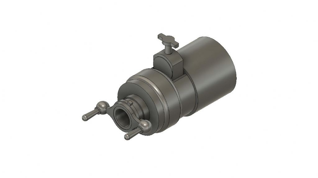
                        The breech in Fusion 360:

                        breechassy v15.jpg

                        After looping round the dimensions a few times I was able to model the Armstrong's breech and barrel successfully – it animates – but have so far failed to get anywhere with a carriage, because dimensions and important details are missing from the 3 alternatives. (Shipborne, fortification and field carriages, all different.)

                        Dave

                        #544338
                        Nigel Graham 2
                        Participant
                          @nigelgraham2

                          I can offer two tips, having been faced with similar difficulties – in fact all I have are photocopies of old publicity photographs of the steam-wagon I am trying to model.

                          You may have to compromise on details of the specific object but you can approach sufficiently closely to the general practices, proportions etc. for the eventual model to be at least a fair representation – but be honest when exhibiting it, and point out that it is a fair representation rather than rivet-counting precise.

                          In any case, it was not unknown for Victorian / Edwardian manufacturers to not build the same thing twice to the last rivet: every picture of my wagon reveals small changes.

                          '

                          1) A photograph is likely to show foreshortening and perspective unless very closely perpendicular to the viewed area. These can be at least partially overcome if you have salient dimensions such as wheel diameters and wheel-base (and on a railway vehicle, the track gauge). If so and assuming the image's elevation angle is small, use the vertical diameter of the wheel as your reference as that will be closer to reality than the horizontal.

                          Also be aware that if you rely on original photos, the prints you see are not necessarily of the specimen described. That caught me out and it was a few years before I discovered this was why my first drawings never looked right.

                          '

                          2) Try to find old engineering-trade designers' reference books. These can be a mine of information on typical practice reasonably contemporary with your subject, so if for example all you have is a couple of museum photos, a General Arrangement works-drawing and a patent spec., you can make the missing details much closer to what was likely to have existed.

                          Remember among the details, controls, steps and handrails are designed to average human proportions so even if you don't have the specific dimensions you can assess fair copies by knowing typical sizes for the hand-grips and the like. These can also help you judge larger parts of the assembly.

                          '

                          3) If possible examine preserved examples if not of the actual subject, then of things of similar age and general forms. Look at how machines were put together; whether square or hexagonal nuts, typical fastener sizes, keys, gibs & cotters, the finish on components, etc.

                          '

                          4) Does your CAD package allow dimensioning scanned photos?

                          To my surprise, I found mine (TurboCAD Deluxe 19) does – but though CAD is pixel-precise within a digital drawing, it is unfair to expect it to pin-point rather vague details on a copy of an ancient photo; and might want to snap to something within cursor range if clearer than the intended point.

                          '

                          5) Whilst on the computer, a spread-sheet is a wonderful tool for scaling and unit calculations; and also good for simple mathematical "models" for designing functional parts' proportions before drawing them.

                          .

                          6) Finally… If in doubt, draw the model part…

                          …. then multiply it by the scale to verify the size is representative. IanT has already examined this aspect.

                          (I tripped myself up on that only yesterday. I designed some Stauffer lubricators for my wagon, then realised I'd "made" the full-size ones over three inches in diameter, needing a gorilla's hand to operate in a space a gorilla's hand would not fit.)

                          #544501
                          Buffer
                          Participant
                            @buffer

                            Thanks

                            Sme Good advice there from all of you actually. I have on and off been doing a bit of CAD work on my model. I ought to update the thread really, it's the RML cannon that I want to make. So far it's going alright but I now know I 'm going to need a bit of help when it comes to working out the gears. Hopefully I'll be able to cut some metal soon.

                            #545089
                            Model Enginerd
                            Participant
                              @modelenginerd

                              I've seen some guys go to the extreme of calculating the lens that was used in an image, undistort it (in programs like Blender) and dial in the guesswork.

                              Photogrametry/scanning can be used as well if the original is available and you have the ability to scan around it. Some impressive models are coming out from new phones with lidar. These points can be placed to scale in 3D space for reference. That said, I think most of the time spent is researching accurate references. Nothing beats accurate orthogonal views. Pureref is a great program for organizing references.

                              Below is an example of a steam donkey I'm working on. I used the technique discussed by others using orthogonal views to generate geometry.

                              steamdonkey.jpg

                              I'm using geargenerator.com to generate the gearing I want, which is constrained to the tooling I have available. Here's an example (You can save your file as the URL, which is pretty cool). I can drop an image of it to scale in this model.

                              Once I drop that in, I can parametrically adjust the steam yarder's geometry to accept the custom gear train and boiler. Dummy models of the pitch diameters are good enough as the critical data is saved in the gear maker.

                              Here's another side project of the Daylight GS-4 I'd like to build some day in live steam. In addition to the main views, section views are also set in 3D space.

                              gs4.jpg

                              Not sure if that's helpful but interested to see how your project is moving.

                              -Z

                            Viewing 13 posts - 1 through 13 (of 13 total)
                            • Please log in to reply to this topic. Registering is free and easy using the links on the menu at the top of this page.

                            Advert

                            Latest Replies

                            Viewing 25 topics - 1 through 25 (of 25 total)
                            Viewing 25 topics - 1 through 25 (of 25 total)

                            View full reply list.

                            Advert

                            Newsletter Sign-up