Creality 3D For Christmas – Impressions so Far

Advert

Creality 3D For Christmas – Impressions so Far

Home Forums 3D Printers and 3D Printing Creality 3D For Christmas – Impressions so Far

Viewing 25 posts - 26 through 50 (of 116 total)
  • Author
    Posts
  • #443876
    Michael Gilligan
    Participant
      @michaelgilligan61133
      Posted by Neil Wyatt on 30/12/2019 11:45:49:

      […]

      It's possible to adjust settings for thin walls, default is generally not to print anything with less than two passes (e.g 0.4 x 2 = 0.8mm with a standard nozzle). Easy to enable single thickness walls and some slicers will attempt thinner walls by reducing the amount of extrusion, but don't expect miracles.

      […]

      .

      From which I must deduce that it is still too soon for me to consider a purchase.

      MichaelG.

      Advert
      #443881
      not done it yet
      Participant
        @notdoneityet
        Posted by Michael Gilligan on 30/12/2019 13:58:23:

        Posted by Neil Wyatt on 30/12/2019 11:45:49:

        […]

        It's possible to adjust settings for thin walls, default is generally not to print anything with less than two passes (e.g 0.4 x 2 = 0.8mm with a standard nozzle). Easy to enable single thickness walls and some slicers will attempt thinner walls by reducing the amount of extrusion, but don't expect miracles.

        […]

        .

        From which I must deduce that it is still too soon for me to consider a purchase.

        MichaelG.

        But can’t they use smaller diameter nozzles, if required? So not necessarily a major drawback. This Sovol SV01 looks like the ‘’bees’ knees’’ for this price range.

        #443891
        Neil Wyatt
        Moderator
          @neilwyatt
          Posted by not done it yet on 30/12/2019 14:04:38:

          Posted by Michael Gilligan on 30/12/2019 13:58:23:

          Posted by Neil Wyatt on 30/12/2019 11:45:49:

          […]

          It's possible to adjust settings for thin walls, default is generally not to print anything with less than two passes (e.g 0.4 x 2 = 0.8mm with a standard nozzle). Easy to enable single thickness walls and some slicers will attempt thinner walls by reducing the amount of extrusion, but don't expect miracles.

          […]

          .

          From which I must deduce that it is still too soon for me to consider a purchase.

          MichaelG.

          But can’t they use smaller diameter nozzles, if required? So not necessarily a major drawback. This Sovol SV01 looks like the ‘’bees’ knees’’ for this price range.

          Indeed, but a 0.2mm nozzle will make your print four times slower…

          #443898
          not done it yet
          Participant
            @notdoneityet

            Indeed, but a 0.2mm nozzle will make your print four times slower…

            Indeed, but it is a hobby for most of us, so not necessarily production before quality. Are nozzle sizes easily interchangeable between jobs? Is deposition rate simply according to nozzle cross sectional area? Certainly power costs are increased at slower printing speeds, but what is the typical average energy use?

            Perhaps I should buy your book – but things advance so quickly with these sorts of technologies. Or maybe I need to add yet another forum to my list – one for specifically 3D printing or one for a particular machine or what?🙂

            #443949
            SillyOldDuffer
            Moderator
              @sillyoldduffer
              Posted by Michael Gilligan on 30/12/2019 10:29:24:

              Posted by Andrew Johnston on 30/12/2019 10:17:25:

              […]

              If you can draw the gear then you can 3D print it […]

              .

              These date back to 2017 … so things may have improved:

              .

              Section of 0.75mm screw thread:

              32 DP Spur Gear:

              p1210621_s.jpg

              .

              At the time, I decided it was too soon for me to buy

              MichaelG.


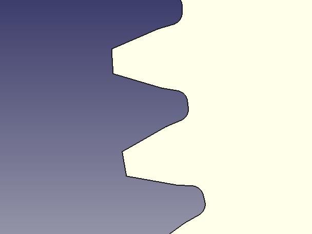
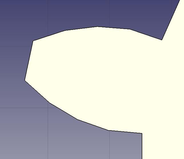
              My results with a 0.4mm nozzle and Cura set to 'Super Quality', claiming 0.12mm drops. First, a close-up of a few involute gear teeth as drawn by FreeCAD's PartDesign Tool: (Blue is background, spur gear is yellow.)

              geartooth.jpg

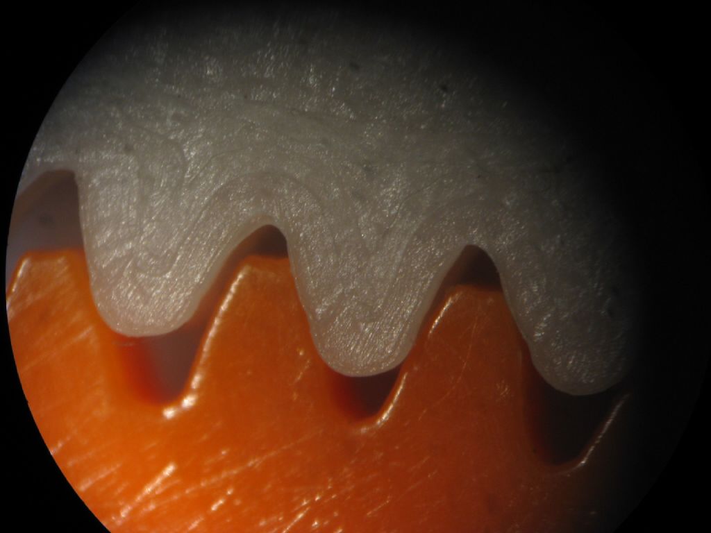
              Second a close-up of my printed gear meshing with a modern orange plastic Meccano gear:

              img_3891.jpg

              Sorry about the photo-quality : I've forgotten how to set the camera and microscope up! But the printed teeth are  considerably better than Michael's examples.

              The printed gear is about 2mm oversize partly because I made a mistake setting the modulus. Meccano gears are 'close to' 38DP or 0.7, one fairly convincing theory being they are intended to mesh with a worm cut with a 1/2" BSW thread.  The gears though, irrespective of gear diameter, were all made with a 38DP cutter. Not very scientific, maybe but an impressive practical compromise – meshing is as good as it needs to be at minimum tooling cost. However, a CAD tool has a brain the size of a planet, and it calculates gear diameter correctly from the modulus and number of teeth wanted, and thus draws Meccano gears slightly larger than the original. Next time, I'll reduce the Modulus to 0.65 and should get a better fit. A 3D printer isn't constrained to standard cutter sizes, it can make any gear wanted, including a mild weirdo like Meccano.

              FreeCAD's built-in gear generator only does involute spur gears. However, there's an add-on Workbench (easily downloaded) that does Cycloids, bevels and crown wheels as well, with more control over the accuracy of the curves. Not tested it fully, but it does spur gears OK.

              Printing this replica Meccano 27A gear (57 teeth) took 1 hour 10 minutes. The 4mm hole left for the axle is 3.8mm and will have to be reamed out. Should be able to lash up a motor tomorrow and break it!

              Dave


              Edited By SillyOldDuffer on 30/12/2019 19:57:14

              #443951
              Michael Gilligan
              Participant
                @michaelgilligan61133

                That’s much better than I expected, Dave star

                Very encouraging

                MichaelG.

                #443954
                Pete Rimmer
                Participant
                  @peterimmer30576

                  It''s pretty good for a printed part, but not nearly good enough for me to consider it an involute tooth gear. The moulded Meccano gears are far better in that respect.

                  #443955
                  Michael Gilligan
                  Participant
                    @michaelgilligan61133
                    Posted by Pete Rimmer on 30/12/2019 20:12:23:

                    It''s pretty good for a printed part, but not nearly good enough for me to consider it an involute tooth gear. The moulded Meccano gears are far better in that respect.

                    .

                    Agreed, Pete … My ‘very encouraging’ means ‘maybe in the next few years’

                    MichaelG.

                    #443961
                    not done it yet
                    Participant
                      @notdoneityet

                      I would be more interested in 14/16DP. 38DP is a bit tiny and accuracy of the involute form must be compromised as tooth size reduces.

                      We have a spinning wheel, completely 3D printed for all the non-metal components. Works well and spares/mods can be printed on open access.

                      **LINK**

                      My wife already has a plan to make a fan-box, for beneath it, as the motor is reported to run a bit too hot.

                      #443962
                      SillyOldDuffer
                      Moderator
                        @sillyoldduffer
                        Posted by Pete Rimmer on 30/12/2019 20:12:23:

                        It''s pretty good for a printed part, but not nearly good enough for me to consider it an involute tooth gear. The moulded Meccano gears are far better in that respect.

                        Yes, I agree. The CAD image shows what the printer was supposed to do while its approximation of the involute is outed by the photo! Better than Michael's 2017 example though and I wonder how much closer to an acceptable curve a 0.2mm nozzle would get on this basic printer?

                        Dave

                        #443981
                        Jeff Dayman
                        Participant
                          @jeffdayman43397

                          If accurate tooth form gears are needed from an FDM 3D printer I'd suggest increasing the size of the gears. Teeth say 4 mm width will FDM print nicely at 0.1 or 0.15 mm layers / finest resolution. 1 mm wide teeth, not so much.

                          As with any technology in the workshop, process to be used needs to be selected that will deliver the required accuracy and precision. For high precision small gearing, injection moulded plastic gears as Pete mentioned, or machined metal or plastic cut-tooth gears, are probably still best.

                          #443989
                          Michael Gilligan
                          Participant
                            @michaelgilligan61133

                            Posted by SillyOldDuffer on 30/12/2019 19:52:31:

                            […]

                            My results with a 0.4mm nozzle and Cura set to 'Super Quality', claiming 0.12mm drops.

                            .

                            I am struggling to comprehend that concept, Dave …. and Harry Nyquist has been no help!
                            Could you please explain [or point me to an explanation of] what is being done.

                            MichaelG.

                            #443991
                            Michael Gilligan
                            Participant
                              @michaelgilligan61133

                              Re my previous post …blush

                              Is it simply that I misinterpreted the word “drops”

                              … are they actually talking about axis resolution ?

                              MichaelG.

                              #444006
                              SillyOldDuffer
                              Moderator
                                @sillyoldduffer
                                Posted by Michael Gilligan on 31/12/2019 07:36:10:

                                Re my previous post …blush

                                Is it simply that I misinterpreted the word “drops”

                                … are they actually talking about axis resolution ?

                                MichaelG.

                                'Drops' was a poor choice of word! I blame inexperience, this is my first 3D printer. I meant 'coming down to height' rather than raindrops.

                                0.12mm, is – I think – the layer thickness, ie a 0.4mm nozzle always extrudes a minimum 0.4mm wide track, but the depth of plastic can be less, in this example 0.12mm high.

                                I'm not clear how the software decides the path taken by the nozzle. For example, I expected the holes in my Meccano gear to be made by not squirting plastic whenever the nozzle passed over the gap. Actually each layer is started by building a wall around the holes, then drawing the gear rim, and then filling in the gaps. Layers aren't simply copied on top of each other; it appears the nozzle lays each succeeding layer at a different angle, creating a lattice.

                                Thinking about it, although the printer starts by dropping the nozzle down to just above bed height, there after it probably lifts the nozzle to add more layers. In which case me typing 'drops' was misleading as well as ambiguous! As penance I shall study the G-code to see what it actually does. Don't hold your breath, g-code is another mystery…

                                Dave

                                #444007
                                Michael Gilligan
                                Participant
                                  @michaelgilligan61133

                                  Many thanks for the clarification, Dave … That makes much more sense yes

                                  MichaelG.

                                  #444014
                                  Anonymous
                                    Posted by Michael Gilligan on 31/12/2019 06:55:03:

                                    …. and Harry Nyquist has been no help!

                                    I suspect the Shannon-Hartley theorum of channel capacity would be more useful. Given the low data rate we either have a narrow bandwidth channel or a low S/N ratio.

                                    SoD: That looks a rather weird gear tooth shape? It almost looks like two straight lines joined by an arc. I'd expect the involute function to be a smooth curve. Once I've sobered up in the New Year (!) I'll have a go at printing some more (smaller) gears and also thin wall features.

                                    Andrew

                                    #444022
                                    Michael Gilligan
                                    Participant
                                      @michaelgilligan61133
                                      Posted by Andrew Johnston on 31/12/2019 11:25:41:

                                      Posted by Michael Gilligan on 31/12/2019 06:55:03:

                                      …. and Harry Nyquist has been no help!

                                      I suspect the Shannon-Hartley theorum of channel capacity would be more useful. Given the low data rate we either have a narrow bandwidth channel or a low S/N ratio.


                                      .

                                      Sorry, Andrew … it was just a throw-away remark

                                      Nyquist would imply that with a 0.4mm nozzle our ‘resolution of detail’ can’t be better than 0.8mm [whereas Dave originally seemed to be saying that 0.12mm was somehow achievable]

                                      … I’m thinking in terms of optical resolution; sensor pixels and the like.

                                      .

                                      Incidentally … Coming back to your earlier remark:

                                      “If you can draw the gear then you can 3D print it:”

                                      I think it would be safer to say:

                                      “If you can draw the gear using a 0.4mm width line, then you can 3D print it:”

                                      MichaelG.


                                      Edited By Michael Gilligan on 31/12/2019 11:56:43

                                      #444023
                                      Pete Rimmer
                                      Participant
                                        @peterimmer30576

                                        It must be possible using PLA because the test print of a dog that came on the card with my printer has features plenty fine enough to make a passable gear. Obviously it was professionally drawn and sliced. I had a look at the gcode and there are a whole bunch of parameters which creality slicer doesn't insert.

                                        #444031
                                        Engine Builder
                                        Participant
                                          @enginebuilder

                                          I printed a 63 tooth gear for my Myford just for fun .It would be quite strong enough to use for a screwcutting change wheel at low speeds.

                                          The files are here, it meshed perfecly. If I remember correctly it will be very small when uploaded into your slicer, looks like is was drawn in imperial units so you need to scale it up to the correct size.

                                          **LINK**

                                          #444039
                                          SillyOldDuffer
                                          Moderator
                                            @sillyoldduffer
                                            Posted by Andrew Johnston on 31/12/2019 11:25:41:

                                            Posted by Michael Gilligan on 31/12/2019 06:55:03:

                                            ….

                                            SoD: That looks a rather weird gear tooth shape? It almost looks like two straight lines joined by an arc. I'd expect the involute function to be a smooth curve. Once I've sobered up in the New Year (!) I'll have a go at printing some more (smaller) gears and also thin wall features.

                                            Andrew

                                            Yes, another interesting diversion into how accurately does FreeCAD render an involute curve?

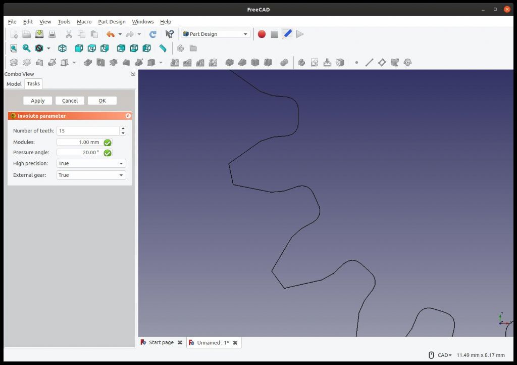
                                            To print the replica Meccano, I generated the gear with Part Design's built-in Gear button in default high resolution.

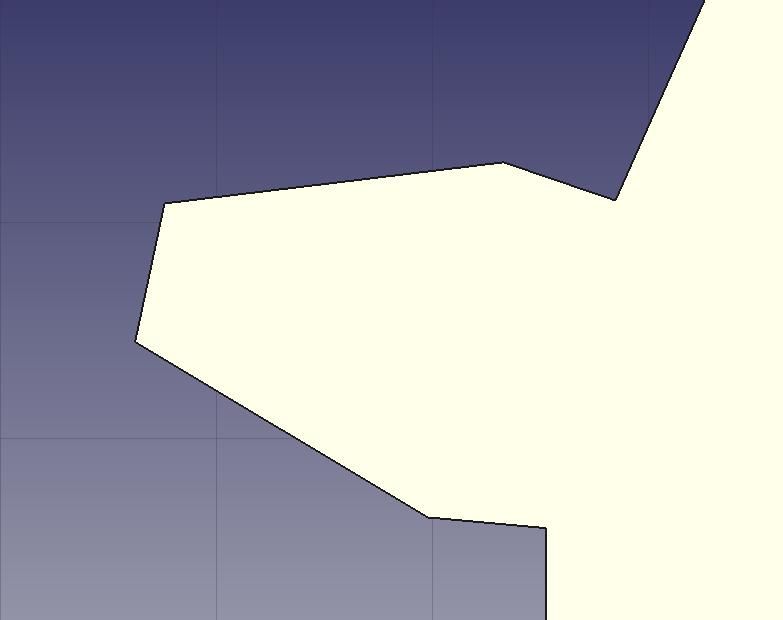
                                            Images following are all of 15 toothed Module 1.0 gears.

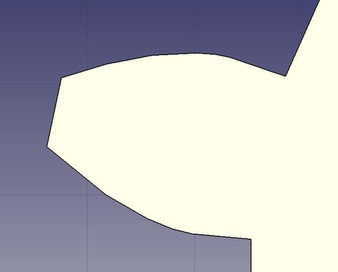
                                            No 1: Standard Gear button in High-resoultion mode. (Not very!)

                                            invstdhi.jpg

                                            No 2. FreeCAD's Gear Workbench (an Add-on download), with the involute approximated by 2 points, very crude:

                                            inv2pts.jpg

                                            No 3. FreeCAD's Gear Workbench, with the involute approximated by 3 points, better:

                                            inv3.jpg

                                            No 4. FreeCAD's Gear Workbench, with the involute approximated by 6 points, good:

                                            inv6.jpg

                                            Of course, these are all approximations and I've not been able to find a true involute curve to compare them with. Yet another challenge: how would one draw an accurate involute? My head hurts!!!

                                            Although I don't expect to draw accurate gears on a basic 3D printer, the point at which it fails is of interest. I think it would certainly produce an acceptable profile as Engine Builder describes for a Myford-sized 63 toothed gear because, shades of Nyquist & Shannon, the errors are low compared with the size of the gear. Not so with Meccano, because the errors are large compared with the size of the teeth.

                                            In order of increasing pain, with the last two causing most problems, I suggest the errors are due to:

                                            1. How approximate the CAD package's involute curve is.
                                            2. Vibration, stepper motor resolution, backlash, belt-drive indexing and the motors losing a few micro-steps. (Presumably a better printer would be fitted with servos.)
                                            3. The melt and smear characteristics of the plastic.
                                            4. The size of the nozzle and feed errors (too much or too little plastic)

                                            Talk of sobering up reminds me there's Prosecco in the fridge. Mustn't let it go off!

                                            Dave

                                            #444040
                                            Michael Gilligan
                                            Participant
                                              @michaelgilligan61133

                                              Involute of a circle … unwind string from a cylinder

                                              [ but that, of course is the 'analog' approach ]

                                              MichaelG.

                                              .

                                              https://en.wikipedia.org/wiki/Involute_gear

                                              http://hessmer.org/gears/InvoluteSpurGearBuilder.html

                                              Edited By Michael Gilligan on 31/12/2019 13:53:55

                                              #444041
                                              Bazyle
                                              Participant
                                                @bazyle

                                                I've just remembered that I have some Britannia cast iron changewheels about 14DP that were made 'as cast' not machined with peg like teeth much like that earlier photo. Good enough for screwcutting. It might be interesting to see what a handful of teeth for say 14DP look like when printed and if that larger size shows any sign of the involute or is still a bit of a splodge.

                                                #444045
                                                Anonymous
                                                  Posted by Michael Gilligan on 31/12/2019 11:54:03

                                                  Sorry, Andrew … it was just a throw-away remark

                                                  Equally it was a throw away reply. smile

                                                  I don't think it's a simple as saying the resolution can't be better than the nozzle size. Certainly one can't print a feature that is smaller than the nozzle size. But if the feature is larger then the accuracy is determined by the accuracy of the moment rather than nozzle size. It also depends upon whether the slicing software takes into account the nozzle size when creating the outline of the part. That's much the same as a CNC mill offseting the cutter path to account for cutter diameter when profiling. My feeling is that Cura does take into account the nozzle size. The internal gear set meshed very well and smoothly. If nozzle width wasn't accounted for the gear set could be out by 0.4mm. I'd be disappointed if I hadn't noticed that. Since I didn't I assume it wasn't there.

                                                  Andrew

                                                  #444048
                                                  Anonymous
                                                    Posted by SillyOldDuffer on 31/12/2019 13:42:40:

                                                    Yes, another interesting diversion into how accurately does FreeCAD render an involute curve?

                                                    For my traction engine gears I downloaded some DOS applications that create a gear in DXF form, which was then imported into my CAD program. I used the hi-res versions which use about 20 points. The original DXF, and gears, were drawn as 1DP and then scaled down to the final size. That way any errors are reduced.

                                                    For the internal gears shown I used the equations for the involute of a circle (*) to generate points in spreadsheet which were then imported into CAD. Can't remember how many points, but probably 10+. Again the gears were designed as 1DP and then scaled to 10DP for the 3D printed gears. Next year (!) I'll take some close ups of the gear teeth.

                                                    One thing that puzzled me when starting to design gears was what is the diameter of the circle from which the involute is created? Turns out it's called the base circle and is the PCD times the cosine of the pressure angle. For small numbers of teeth the base circle can be larger than the root diameter, ie, no involute curve near the root. In practise this isn't too important as the root diameter is smaller than theoretically needed to give clearance. For the internal gear i approximated the curve between base circle and "root" diameter by a straight line.

                                                    The old (50+ years) metal Mecano gears I have are a bad approximation to involute teeth.

                                                    Andrew

                                                    * MG is correct, an involute is simply a curved derived from another curve; the involute used in gear design is specifically the involute of a circle.

                                                    #444165
                                                    Andrew Entwistle
                                                    Participant
                                                      @andrewentwistle

                                                      Hi,

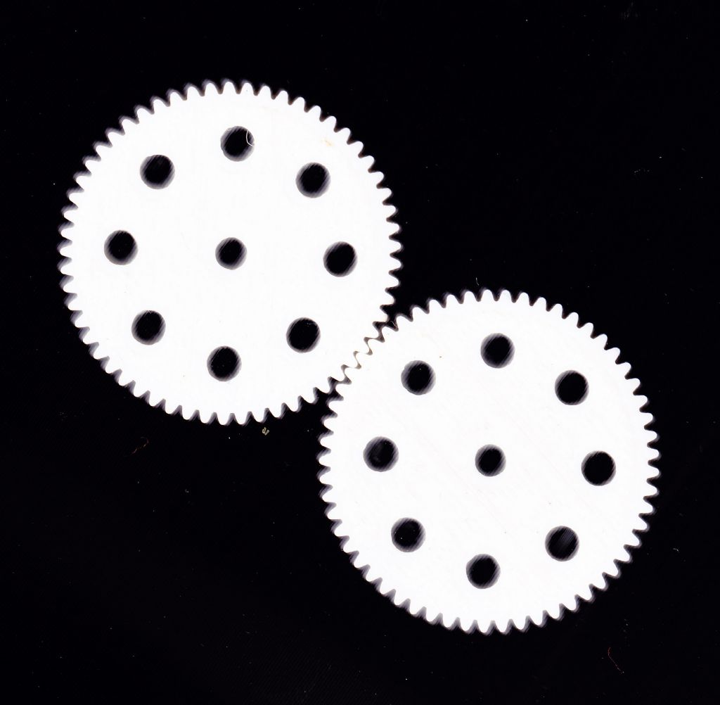
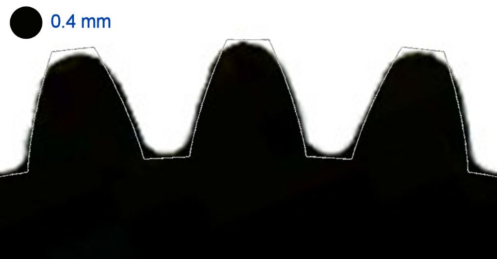
                                                      I printed a couple of 4mm thick Meccano style 57T gears, modelled using the CAMBAM involute gear generator using a quite old 0.4mm nozzle. The first image is a scan of the gears, top face towards the scanner glass. The second image (inverted) shows the deviation from design profile, along with a 0.4mm circle for scale. Material is PLA, 0.1mm layer height.

                                                      57T Meccano gears

                                                      57T tooth form vs involute

                                                      Edited By Andrew Entwistle on 01/01/2020 14:30:53

                                                    Viewing 25 posts - 26 through 50 (of 116 total)
                                                    • Please log in to reply to this topic. Registering is free and easy using the links on the menu at the top of this page.

                                                    Advert

                                                    Latest Replies

                                                    Viewing 25 topics - 1 through 25 (of 25 total)
                                                    Viewing 25 topics - 1 through 25 (of 25 total)

                                                    View full reply list.

                                                    Advert

                                                    Newsletter Sign-up