Hello Chris,
Quite a lot to cover in reply so I will break it into sections
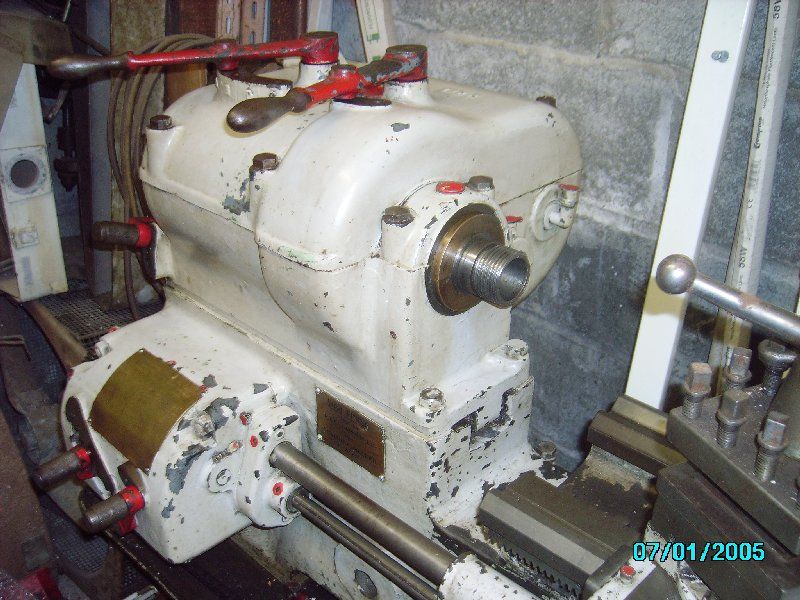
1 The leadscrew and power shaft bracket. It looks to have two small oiling holes, one to each shaft bearing. The larger diameter hole to the right of the hex head bolt is probably a dowel hole, with the dowel fitted to the bed. The whole will be mounted on a machined seating to keep things square.
2 You mention protecting the feedscrew and power shafts if you still have them in place when slinging the bed. The usual trick is to bridge over them with timber either side so that the sling is held away from contact and no side loading to them can occur. You DON'T want to bend those, the L'screw in particular.
3 Gearing I'll go over the headstock selectors as an example. My earlier thought some while ago was incorrect in thinking the RHS lever was for reversing the spindle drive.
I've looked again at the open headstock picture on Tony Griffiths website and there are indeed 8 different spindle speeds possible. The left hand selector lever moves a spaced out cluster of 4 gears on a common carrier along the shaft furthest fro camera that brings power in via the input clutch. If you look at that picture you will see a long key runs the full length of that shaft to take the drive into the cluster. The selector arm allows one meshing at a time with the next shaft nearer the camera; you will see the different sized gears on that shaft to mesh individually. The gear spacings allow only one meshing for one position.
This shaft is known as a layshaft [just a fancy name for a transfer shaft] and it is meshed selectively as described above. All 4 very visible gears are in fixed positions on the shaft and on the extreme right is a barely visible small 5th gear, also keyed to the layshaft, which meshes with the big gear nearest the chuck. It has a dog clutch formed on one side of it..
Two gears back on the laysheft, as shown in the picture, is a group of three gears,, all meshed together, across the full width of the gearbox.On the spindle shaft, the gear on the left also has a dog clutch on it's right hand end.
It is free to rotate on the main spindle. The big gear on the right side of the dog clutch is also free to rotafe on the main spindle.
Now this is the clever bit. The dog clutch is keyed on a slider to the main spindle and drive to the spindle is taken through that key, either from the gear on the left of it, or the big gear to the right. The dog clutch position is selected by the right hand lever on the top of the headstock and this gives the final 4 speeds to the spindle.
Gears not coupled together are threfore free to rotate next to each other, and at different speeds.
It takes a bit of thinking about, but if you make a sketch on paper and draw all 8 of the gear positions as a series, linked as they would be when engaged, I think you will see the logic of it
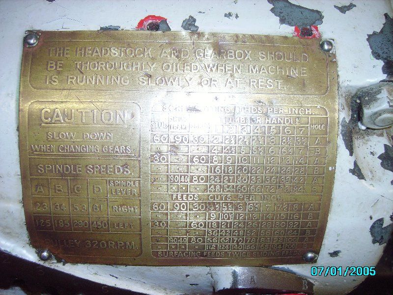
4 Your interpretation of Phil's plate Well yes, I agree with you, the gearbox would crash, so I'll look at that too and try to unravel it; it can't be as you are reading it
I think today's work is quite enough for now
Best wishes
Brian
Doug Goding.


