CovMac Lathes

Advert

CovMac Lathes

Home Forums Beginners questions CovMac Lathes

Viewing 25 posts - 226 through 250 (of 433 total)
  • Author
    Posts
  • #171025
    Phil Whitley
    Participant
      @philwhitley94135

      Hi Chris, To strip and rebuild the EE motor, proceed as follows:

      Clean up the pulley and shaft at the drive end, and remove the key, with a lever if it has a tang on it, with a pair of molegrips if it hasn't or the tang is broken. This may involve warming the pulley with a blowlamp and tapping the pulley a little further on to the shaft to free the key. Believe it or not they usually come out quite easily. Once the key is out, clean the end of the shaft to bright metal, remove any burs, and remove the pulley. Behind the pulley, and at the other end in th same place you will see the three screws or bolts visible in your pic that locate the bearing covers. These usually go right through the motor end plate casting and screw into a bearing retainer plate inside the motor. Remove these screws at both ends. Clean the outside of the motor and, at the drive end, put a single centre punch mark adjacent to one of the through bolts (The ones that go right through the motor and hold the end caps onto the stator) on the end cap, and a matching mark on the stator. Now go to the non drive end and put two punch marks adjacent to a through bolt, and two on the stator. These marks are for reassembly to make sure it goes back together in the same orientation it was originally assembled in. If you look carefully, these marks may already be there if the motor has been stripped previously. When you have done this, remove the four through bolts, and you should be able to use a hide faced or copper/lead mallet to split the motor by gently tapping the end cap flanges with a brass drift, or the soft hammer if you have one. I used to use compressed air (and a mask!) to clean out the dust, but someone pointed out that a vacum cleaner is better, and I can't argue with that as long as all the dust and debris is carefully removed from the windings. It can then be washed out with water free alcohol (anhydrous alcohol) and set aside somwhere warm to dry.Wash the end caps and other components in parrafin or engine cleaner (or diesel or central heating oil), and carefully wash out the bearings, bearing housings and grease holes with parrafin and examine the bearings for any signs of pitting, corrosion or rough running when you spin them. By the way, If the bearings stay on the rotor shaft, there is no need to remove them unless you need to replace them, All this can be done with them in place, we used to take them off most of the time, but we had the equipment! If there are cooling holes through the rotor, clean these out thoroughly when you clean the rotor.

      Examine the stator windings, and the tails that go from the windings to the connector block where the cable attaches to the motor. If the insulation on these is cracked or "sticky" they can be sleeved with glass fibre sleeving, or replaced with new cables, which are soldered to the ends of the coil windings. If you remove the tails from the connector block be sure to mark them up so you can put them back in the same place. Now is the time to get the stator megger tested to confirm that the windings insulation is still good. Once this is confirmed, and all the parts are cleaned, you can begin reassembly. If it fails the megger test, send the whole motor for a rewind, not just the stator, as this will enable the rewinders to rebuild and test the motor (thus saving you the following

      Firstly, with clean hands, repack the bearings with HMP (high melting point) grease used for car wheelbearings and available at you nearest halfords or probably much cheaper from and independant car store! There are two ways to proceed, and TBH I have used both, and it makes very little difference. Some people prefer to put the rotor back into the stator first, then fit the end caps (I usually do it this way, especially with really big motors) others will fit the rotor to the drive end end cap (the one with the single punch marks) then fit the bearing retainer screws, and fit the assembly to the stator. Line up the punch marks and then align the bearing retainet plate with the screw holes in the rear end cap and fit it to the stator, lining up the punch marks again. Loosly fit the through bolts, then put one of the bearing retainer bolts through the holes in the end cap (without fitting the outer plate, and see if you can pick up the thread in the bearing retainer plate You can isert a peice of bent wire through the vent slots to hold the plate against the end cap, and check for alignment with a long thin screwdriver (this process is usually much easier than it sounds here!)once you have one bolt started, put another bolt through the outer plate, and fit that to one of the other bolt holes, then remove the first bolt, and swing the plate into place. Once all the bolts are in loose, tap the endcaps a bit further onto the stator making sure they are going on square, and toghten the through bolts alternately and diagonally, checkin the rotation as you do so. tighten the bearing retainer bolts and refit the pulley loosely. do the final alignment when the motor is back on the lathe.

      I then used to pass them over to Mick, who used to spend the last hour of the day testing them and spraying them in "Jeffersons" Blue. Motors from 1 to 10 HP we used to do four a (good) day, but that was in a fully equipped (well, they said it was!) workshop. Good luck!

      Phil

      Advert
      #171029
      Phil Whitley
      Participant
        @philwhitley94135

        Ah, You have all been posting! I agree with Brian, get a replacement starting capacitor, that one has hung around for years without starting, and they go of with a bang like a thunderclap, followed by a shower of aluminium foil conffetti, liberally sprinkled with (possibly) PCB's.(look it up on wikipedia and be horrified) What Neil says is also correct, we have discussed a 16A socket for the motor in emails I believe. Also what he says about the MCB being the delayed type (type B or C) but take advice on this as my knowledge on these little monsters is not bang up to date. I know that VFD's and phase convertors play havoc with them (and RCD's), and TBH I don't believe them to be anywhere near as safe as we are led to believe, there used to be a rule that "any mechanical device fitted to an electrical circuit in order to provide a level of electrical safety MUST FAIL SAFE. Of course that was under the old IEE regulations, which have now given way to the IET regulations and this requirement has dissapeared. Needless to mention then, that a significant number of the IET board are manufacturers, not engineers, and both MCB's and RCD's do not fail safe, wheras a fuse ALWAYS fails safe. So if a fault develops, and your MCB is faulty, the only protection you have left between you and the transformer way out in the network is the supply authorities "cutout" fuse, fitted on the incoming supply next to your meter, and rated at between 60 and 100 amps! In a few short years, if not already, those MCB's and RCD's WILL be "Made in China" Then the fires and deaths will start. Fetch the screens Nurse, he's ranting again!!

        Phil

        #171030
        Phil Whitley
        Participant
          @philwhitley94135

          Also meant to say(before I "went off on one&quot that the quoted amperage on a motor is the FLA or full load amps, I would expect it to draw somwhere around 8 to 10 amps in this type of machine, although you can't rely on that, the 16A socket is a must!

          #171031
          Phil Whitley
          Participant
            @philwhitley94135

            Hi Chris, It's ok, I have calmed down a bit now, You and Neil have put your finger on why I wanted to convert my Covmac to Three phase, it is much more efficient, and therefore economical, but you also have to look at spending the money on extra power for the motor you have got, or spending it on a new motor at around £300, which buys a lot of electricity! I think I will go with Chris, and keep mine historically correct as well.

            Phil

            #171033
            CHRISTOPHER MILLS 1
            Participant
              @christophermills1

              Phil,

              I am absolutely at one with you on keeping the originals.

              Aside of that, I began the day thinking I was beginning to understand the motor, but am back well behind square one tonight.

              Much more discussion is needed before I fire up the EE. I will take it apart and clean it all out, etc. I will not fire it up, before we have full forum agreement.

              I neither wish to spoil this lovely old motor, nor fry myself.

              My mind is spinning faster tonight than the motors!!

              Architecturally, yours is even more interesting, I feel, than mine. It looks odder, and quirkier.

              Perhaps the secret is in the insulation, or as Brian has suggested tonight, in the rubbers!!

              Mine's a half, if you must.

              #171035
              Phil Whitley
              Participant
                @philwhitley94135

                Don't worry Chris, It sounds a lot more complex than it actually is when you set it out stage by stage like I have done,

                Don't wonder how to do it, get started and wonder how you did it!

                Phil.

                #171059
                CHRISTOPHER MILLS 1
                Participant
                  @christophermills1

                  After sleeping on it all, I have decided I am four-square with Phil – do it – before you get too old to do it.

                  But, I will do it carefully, and will not actually fire up the EE motor until we have forum consensus.

                  I will open it up, clean and test it, and post photographs of its innards. Then we can decide how I actually fire it up.

                  I will also consult with my next door neighbour, the venerable Professor Jayantilal Kotecha, electronics engineer (ret'd) trained in Calcutta, Madras and Nairobi – coming up for his 80th birthday, shortly.

                  Apparently, there is nothing electrical, and nothing with a motor, that he can't get going!

                  Today, I am building the super pallet for the CovMac bed.

                  #171090
                  CHRISTOPHER MILLS 1
                  Participant
                    @christophermills1

                    Here is the custom-built pallet for the CovMac bed – it is upside down here – the two 2×3 inch wooden frames either side are needed below to allow the crane to go in underneath to drop the bed on. Under these two frames will be two stout plywood boards, with four castor wheels each. The castor wheels, about 4 inches in diameter, are rubber faced, and hopefully they will run better than the crane's steel wheels. The pallet is about 85 inches by 28.

                    The pallet has no lifting duties, it is just for the bed to sit on. The wheels are rated at 600 KG per four – so we are running them only to about 50% weight capacity. I really do not want one collapsing on me.

                    The pallet is courtesy of British Gypsum, a cut down 8 x 4 plasterboard pallet. I have reinforced it everywhere I think it is needed. I spoilt my neighbours' Sunday by building it.

                    CovMac Pallet

                    wheels

                    #171344
                    CHRISTOPHER MILLS 1
                    Participant
                      @christophermills1

                      CovMac Final Move Due Tomorrow – Yesterday, we got the lathe bed onto the pallet, and, after it was well lashed down, (even the bed alone is very top heavy – and it still has carriage and apron on) the assembly works well – it moves a little like pushing a large motorcycle. We did not even need plywood boards, once free from the shed; rubber faced wheels coped very well with roughish concrete.

                      It is now out of the shed, covered by a tarpaulin, waiting to be lifted tomorrow. Incidentally, we raised the main bed on only the 1/2 ton crane setting, for extra jib extension, and it was just fine – there must be a built in margin of safety to it, for I am sure the bed weighs well over that.

                      Martin Whittle was again a superb help, and with his friend Bob Minchin, I was in very good company of engineers yesterday. Aspects of my pallet design needed improvement. Stability is all important with this kind of weight.

                      We got the compound slide assembly off, too; that needed occult knowledge, and its tool-post was right in the way.

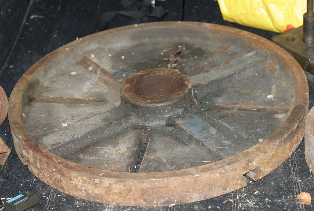
                      Told by Brian Wood to take a very good look around the shed for small lathe parts which might have been missed, I found the 24 inch face-plate!

                      In original dark grey CovMac paint, it is an absolute monster. It takes two men just to lift it, and getting it onto the lathe must have been a real challenge – if it was, indeed, ever used.

                      I had missed it on earlier visits, because it was lying horizontal, about 18 inches off the ground under a bench, and looked every inch like a coffee table top. It was only yesterday I spotted the key-ways, and hauled it out.

                      Will get some "big-lift" pictures tomorrow. We did nothing spectacular yesterday, but tomorrow it has to go reasonably high to get it onto the flat-bed truck.

                      Monster Face-Plate

                      #171350
                      CHRISTOPHER MILLS 1
                      Participant
                        @christophermills1

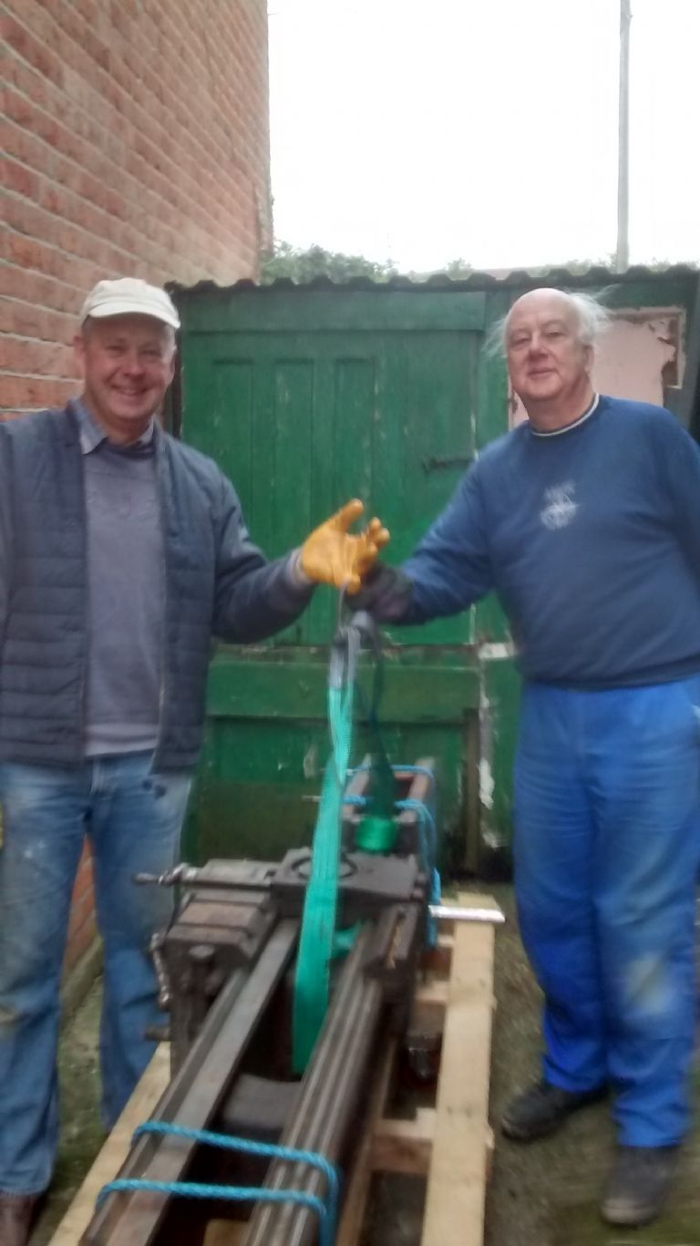
                        CovMac Engineers – Here are Martin Whittle, on the left, and Bob Minchin, CovMac engineers. I need to use a crane when I am working, but they can lift the bed with one finger each. It is all in the training. I would have been a bit lost without these highly trained gentlemen.

                        Martin & Bob

                        Here is the bed before being lifted – just bare bones left, bed and headstock, after all removals. The compound slide came off just after this picture was taken. It was beyond my comprehension how that came off. The visuals do not fully convey just how heavy it all is, and how much extreme care must be taken in shifting very heavy pieces of metal.

                        Remains

                        Now the 13" Geared head CovMac is under a tarpaulin and awaiting a final lift, tomorrow morning.

                        I am off buying strong tie-down ratchet straps, for give this CovMac bed an inch, and she will roll over sideways.

                        Tarpd

                        The upper little brass plaque on the tailstock end bed is the War Office's ownership label and the lathe's serial number.


                        Edited By CHRISTOPHER MILLS 1 on 03/12/2014 09:25:26

                        Edited By CHRISTOPHER MILLS 1 on 03/12/2014 09:30:23

                        #171351
                        CHRISTOPHER MILLS 1
                        Participant
                          @christophermills1

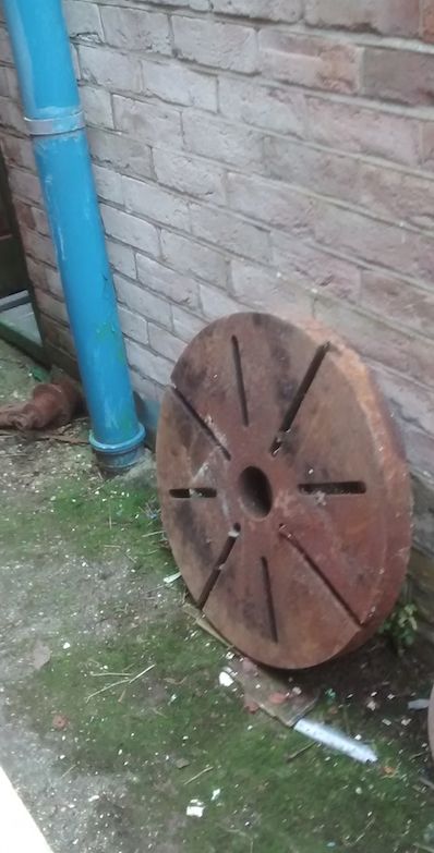
                          24 Inch CovMac Face Plate – Here is a front face view of the 24 inch face plate, of which I have earlier posted the reverse side.

                          It does not look as big as it really is, here, but, I promise you all, this thing is truly mighty. It has a bolt jammed in one of the slots, suggesting that it was actually used for a job, once.

                          When the restoration of the lathe is complete, I would like to mount this plate, once, for a photograph – but I cannot see me ever actually using it. I am really looking forward to cleaning it up. It has some surface rust, but nothing too bad.

                          Big Plate

                          #171358
                          Ian S C
                          Participant
                            @iansc

                            Got a mate who has a medium size Pratt & Whitney lathe of 1930s vintage, with 14" chucks, he has a crane mounted on the wall of his shed for moving chucks, before the crane was built, I changed chucks once, never again. It would be worth your while setting up something along these lines with your lathe.

                            Ian S C

                            #171363
                            CHRISTOPHER MILLS 1
                            Participant
                              @christophermills1

                              Ian, Many thanks for that – I can certainly see two men struggling with this titan.

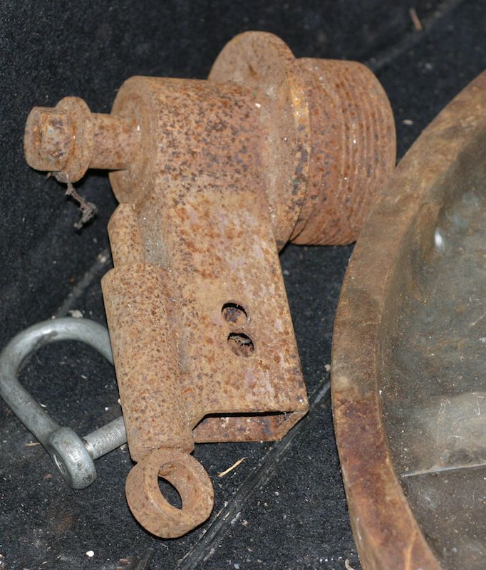
                              With the big plate, came what seems to be a crude form of dividing head. This is probably beyond restoration, for it has been used, for many years, as a door stop in the yard, and is very heavily rusted up. It appears, as Bob Minchin pointed out to me, to take a gear wheel, and uses the teeth on the gear wheel to do the dividing. It is screwed to fit into the centre of the big face plate wheel. Beyond that, I do not know too much – it looks a bit home made.

                              dividing head

                              #171365
                              Brian Wood
                              Participant
                                @brianwood45127

                                Chris,

                                Now that is a candidate for soaking in apple cider vinegar, who knows what will emerge. As Bob Minchin says, it looks for all the world like a simple gear tooth operated indexing tool to mount a chuck on, clearly 'home made' .

                                Ian's suggestion of a wall mounted crane is a good one, it could be made to be quite elaborate with a carriage rather than a simple pivot.

                                Have a fun day

                                Brian

                                #171375
                                Gordon W
                                Participant
                                  @gordonw

                                  It used to be common for a big lathe ,or a mill, to have it's own little crane. Used for lifting jobs as well as chucks etc. If the machine did not have one the operator might make his own, this would save time waiting for the shop crane, worth it on piece-work.

                                  #171381
                                  Bazyle
                                  Participant
                                    @bazyle

                                    If the 'dividing head' screws onto the faceplate i suggest it might have been just a device to lifting it and/or holding it on a frame when setting work out on it.

                                    On looking again I see what I had taken as a lifting eye does look like a detent. for gear dividing.

                                    Edited By Bazyle on 03/12/2014 13:11:24

                                    #171383
                                    CHRISTOPHER MILLS 1
                                    Participant
                                      @christophermills1

                                      Thanks Gents – So could it have been that the big face plate might also have been used flat as a working, holding and measuring surface?

                                      #171402
                                      Roger Williams 2
                                      Participant
                                        @rogerwilliams2

                                        Chris, perhaps you could rig something up like this for lifting stuff on the CovMac. You mentioned your lathe has a hole in it for lifting, like my DSG, so with a bracket made up to fit in said hole, 4 small bolts attaching it to the lathe, and a 1 inch bolt welded on to slip the crane tube on, you are away. I extended the bracket to the concrete for additional support if needed. Small trailer winch off Ebay and an old pulley, seems to work OK. Cheers.

                                        22022014110.jpg

                                        #171404
                                        CHRISTOPHER MILLS 1
                                        Participant
                                          @christophermills1

                                          Roger,

                                          Many thanks – is the face plate held on a piece of bar, so that you can rotate it? Would it be possible for us to see some detailing from its reverse side?

                                          Using the eye on mine to mount a crane seems a great idea

                                          Your DSG is a real beauty – how old? It looks in fabulous condition.

                                          It makes the dear, old CovMac seem of positively modest proportions.

                                          Best wishes. Chris.

                                          #171420
                                          Brian Wood
                                          Participant
                                            @brianwood45127

                                            Hello Chris,

                                            Roger is showing a big 4 jaw chuck gripping a bar welded to the upright from the crane hook, all built so that it is aligned through the centre of mass of the chuck. A rear view won't show you nuch in common with the Covmac, that chuck is a camlock fitting onto a matching large diameter taper on the lathe spindle. The main difference over your screwed nose is greatly improved accuracy and complete freedom to run the lathe in reverse without any risk of the chuck uncrewing itself on heavy work. A big chuck of maybe 200 lbs of so coming off the lathe at speed is a deadly thing, taking everything in its path until running out of momentum

                                            That is a lovely lathe Roger you are a fortunate man. It will outweigh your Covmac Chris , big as it is. I guess it is also a lot younger..

                                            Brian

                                            #171423
                                            Roger Williams 2
                                            Participant
                                              @rogerwilliams2

                                              Hello Chris, the DSG is 52 years old, bought as a retirement "present" to me a couple of years ago. My wife was absolutely everjoyed when I bought it. face 4 It came from a small factory that was going to CNC, and evidently had been well looked after. Ive changed the motor from 5 to 3hp, but she will still take some decent depths of cut , enough for my inexperienced level of skill!.The missus sometimes groans about how to drag the bloody thing out of the garage when Ive snuffed it !!!.

                                              #171426
                                              CHRISTOPHER MILLS 1
                                              Participant
                                                @christophermills1

                                                Roger,

                                                I sincerely hope you are not going to snuff it soon, so your wife will not have the problem of disposal.

                                                I can give her a few names to approach, who might drag it out for her!!

                                                Can I be really rude, and ask what went paid for your DSG?

                                                It is really interesting, watching prices of old lathes on eBay.

                                                There are two prices, asking prices of 'dreamers' trying to off-load, and the reality: At what prices do lathes actually change hands.

                                                Then there is the appalling 'scrap value ' price. Ghastly.

                                                My CovMac would have been scrapped without my commitment. Nobody else wanted it.

                                                But knowing what I know now, I would have had it for half the price I paid – its scrap value plus just a little bit. Rather than my romantic price – of an antique I really wanted.

                                                Best.

                                                Chris.

                                                #171429
                                                Roger Williams 2
                                                Participant
                                                  @rogerwilliams2

                                                  Hello Chris, it was on Ebay and probably paid over the odds for it, but buying via my son in laws company, after clai ing back the vat, cost me £1600. A bit much, but, hey ho !. On the other hand, I dont smoke or drink or look at other women ( that bit was a lie ), so bugger it !!. Regards, Roger

                                                  #171441
                                                  CHRISTOPHER MILLS 1
                                                  Participant
                                                    @christophermills1

                                                    Well, hardly anything at all to pay for the DSG. How did you shift it? It looks between 2 & 3 tons?

                                                    #171460
                                                    Roger Williams 2
                                                    Participant
                                                      @rogerwilliams2

                                                      Chris, yes, just over 2 tons. I was going to get the factory I bought it from to load it on to my big trailer, but thankfully,they had no means of loading it, because it was a 400 mile round trip , I would have been right on the GTW limit, and shi****g myself all the way home !!!. So, Heaver Bros' in Exeter collected it and dropped it right outside my garage, or just in a bit. Id previously drilled a hole in the end of my garage wall, with a big plate on the outside and an eye and a shackle on the inside, using a Pulllift winch, pulled the lathe in on some inch bars. The drive and garage has quite a slope on it, but with a friend, we managed it . Incidently, the 8 wheeler that delivered the lathe on it had a big Fassi (impressive) remote controlled crane on it that can lift 3 tons , with a reach of 16 metres.

                                                      In retrospect, considering the trouble your having moving the CovMac in pieces, I would have had a hell of a job getting mine off a trailer in one piece. Severe trauma and injury springs to mind !!. frown

                                                    Viewing 25 posts - 226 through 250 (of 433 total)
                                                    • Please log in to reply to this topic. Registering is free and easy using the links on the menu at the top of this page.

                                                    Advert

                                                    Latest Replies

                                                    Home Forums Beginners questions Topics

                                                    Viewing 25 topics - 1 through 25 (of 25 total)
                                                    Viewing 25 topics - 1 through 25 (of 25 total)

                                                    View full reply list.

                                                    Advert

                                                    Newsletter Sign-up