Posted by JasonB on 04/04/2011 18:41:43:
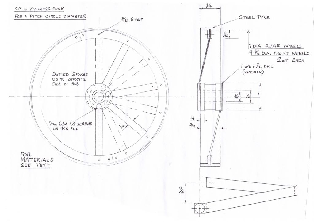
Two other points on the hub cross section
1. No diameter shown for the reduced central section, assume it should be about 7/8″ Would also look better with radiused internal & external corners as it represents a casting
2. The 1/4″ dimension given for the hub flanges is not in proportion to whats drawn, the 1/4″ should have been dimensioned from the outer face of the cover “washer” to the back of the flange.
Jason
Oh and no idea what the bits in the bottom right are meant to be, hopefully the next installment will enlighten us

Edited By JasonB on 04/04/2011 18:47:30
Like Jason,I have no idea quite what the figure bottom right represents.Also missing from the drawing is the spoke thickness.Is it supposed to be 18g or 16g as implied in the text,or if the angle rims are equal at 5/16,should the spokes be 1/8″ thick?
And despite giving the tyre width of 3/4″ twice on the drawing,there is no mention of how thick that should be.
Why not put all the dimensions needed to make the wheels on the drawing,especially as the series is aimed for the beginner?
Again it poses the question about the standards of some of the drawings published in the magazine,whereas those excellently provided by Ray McMahon and Peter Rich for their respective locomotive designs should be what all contributors should aim for.
I hope Mr Webster and the Editor accept my comments in a constructive way,as I think this is a most interesting project.
Whether we love or loathe the subject,technical drawing is the language of engineering,whether at full size or in ‘our’ scales.
David Clark 13.


