A few months ago, I decided to have a go at making a 1:12 scale Cosworth V8 DFV Formula 1 engine.
It will be a 2-stroke running on air (or CO2?) with a bore of 7.2mm and a stroke of 5mm.
I want to share my progress so far as I’m sure I will need some advice.
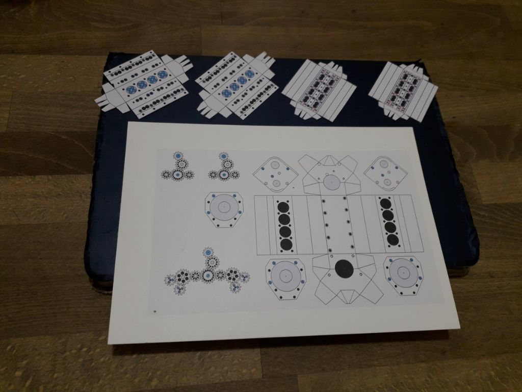
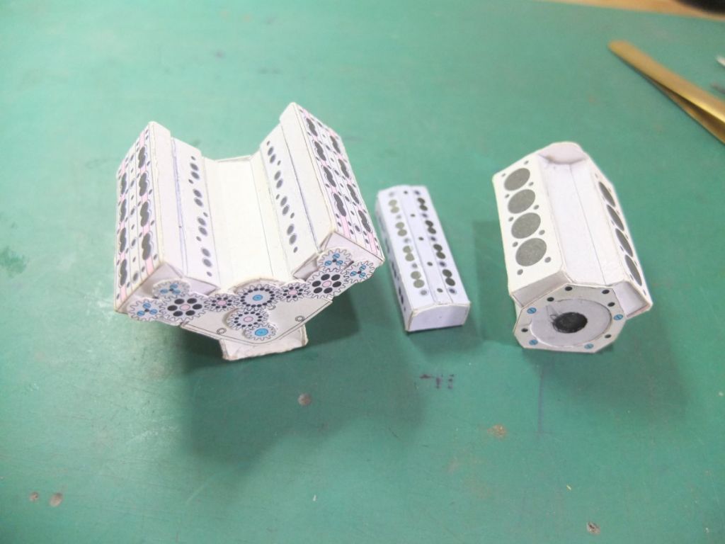
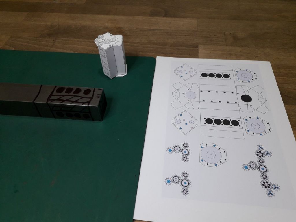
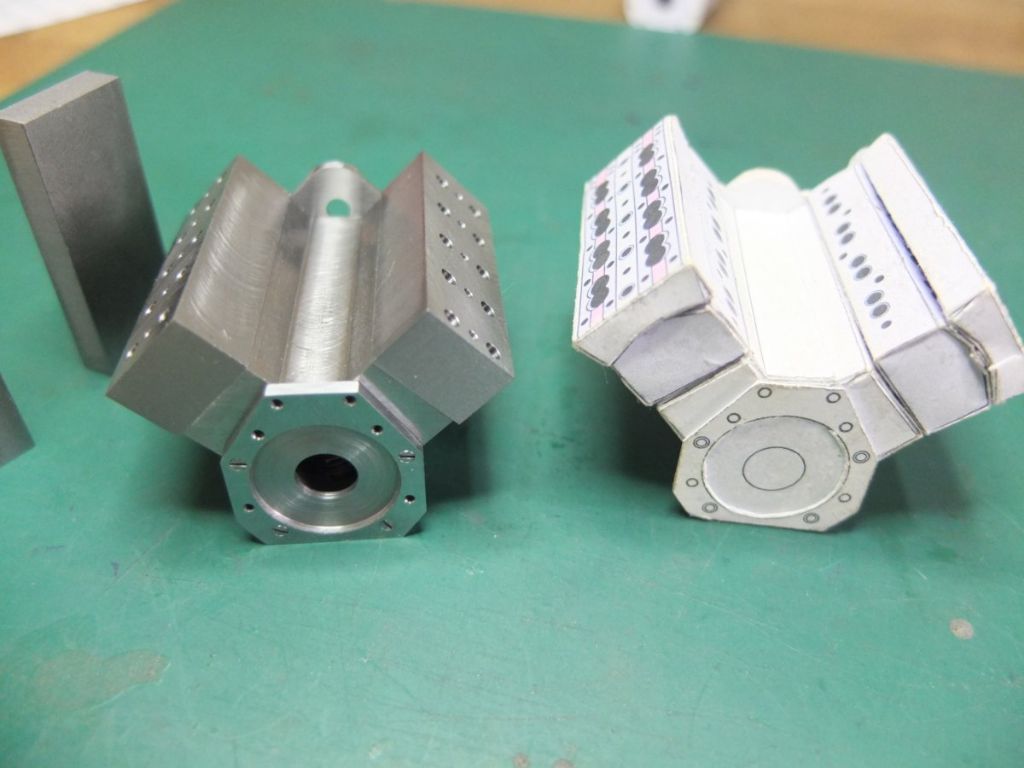
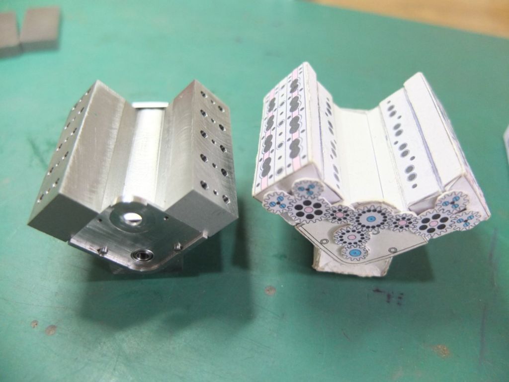
After making the drawings, the first thing I did was make card models of the main components.
This helps me visualise things and see if any screws interfere with each other etc.
The block started life as 1” square mild steel bar.
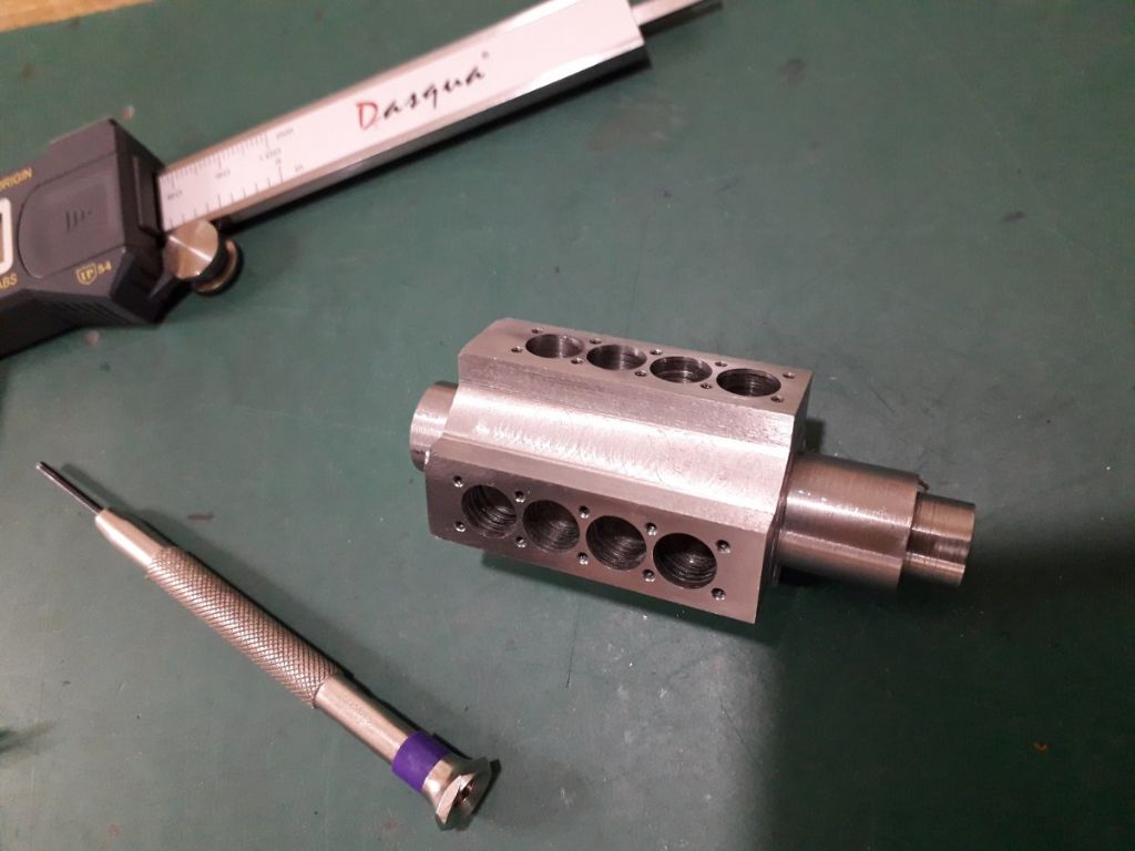
I sawed of a piece about 3” long and this was clocked in the 4 jaw and eccentric bosses, on the crank centre line, were turned at both ends. This gave me an accurate way of holding it while boring out the cylinders and milling the block to shape. In the picture below, the milling is part done.
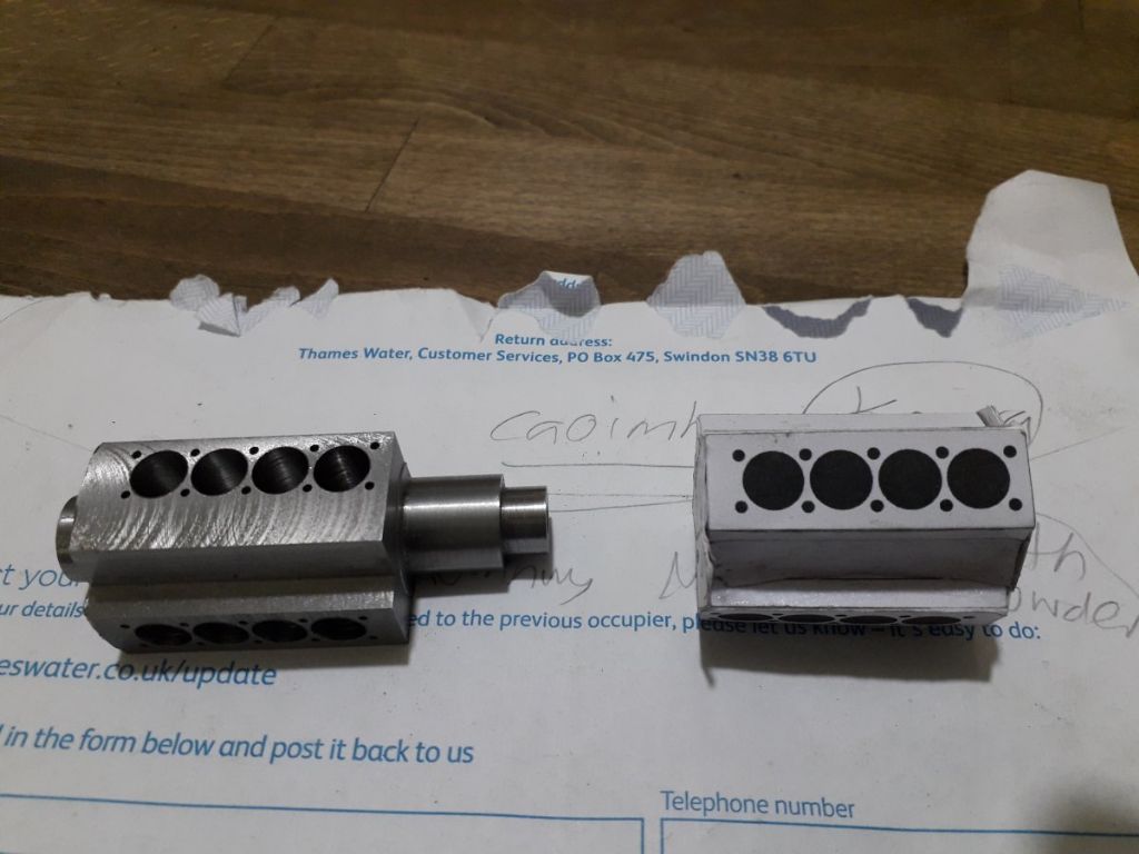
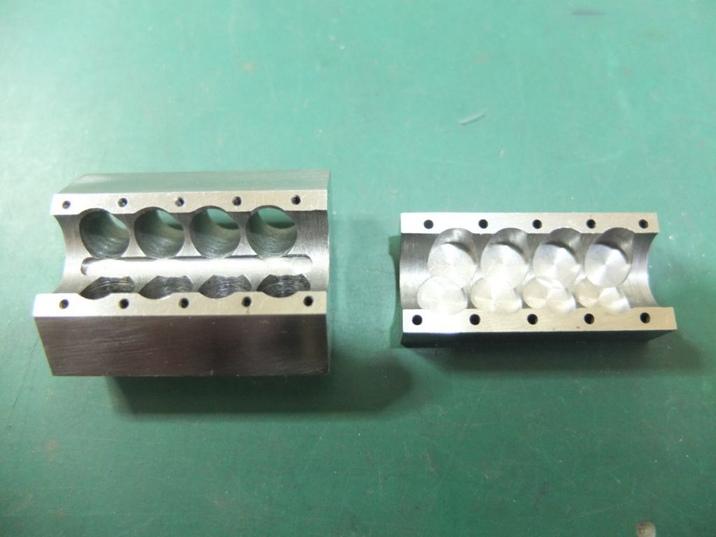
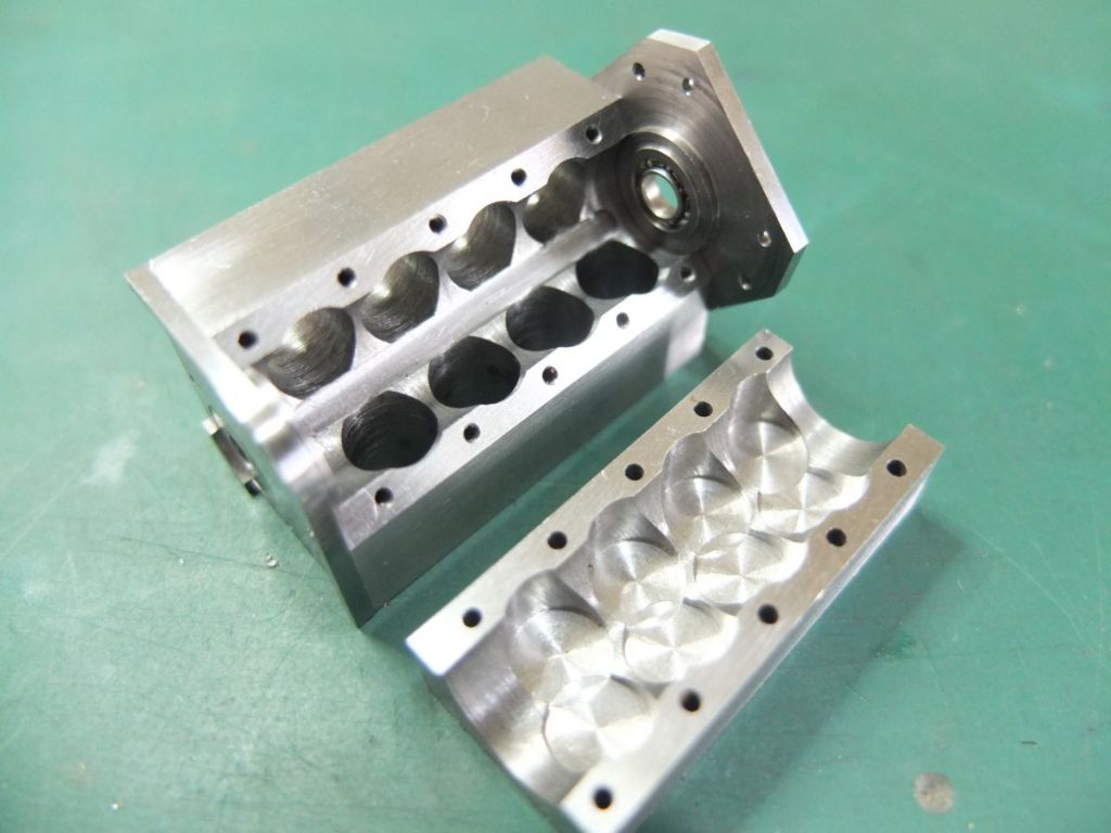
The block, milled to shape. The bores are a bit rough but true. They will have brass liners anyway.
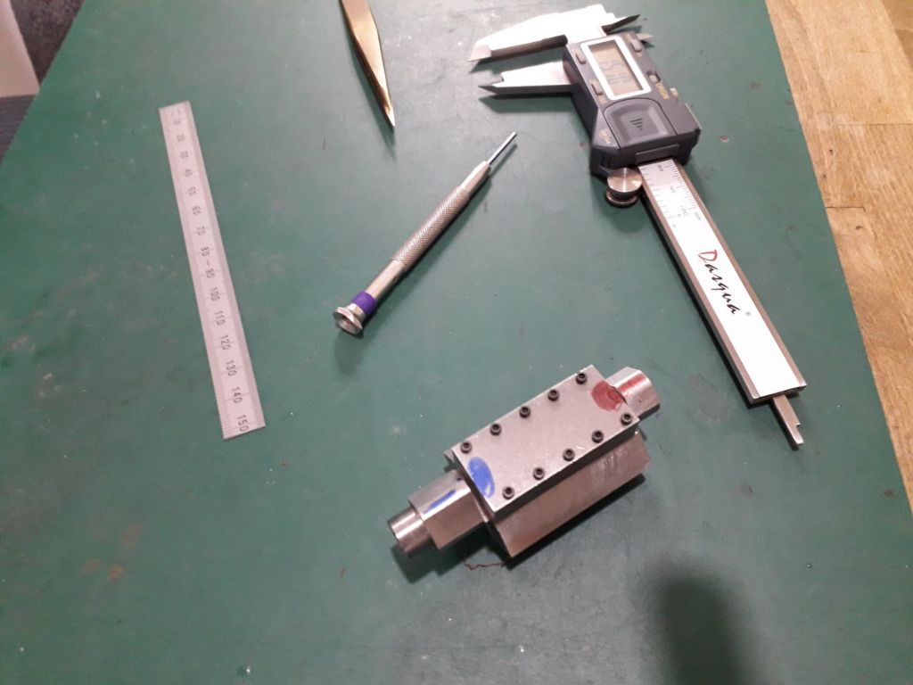
The block was drilled and tapped and the sump blank bolted to it.
The whole assembly was then drilled and bored out as one piece and the bosses removed.
The next job was to remove some metal from the inside of the sump and the block to provide clearance for the con rods.
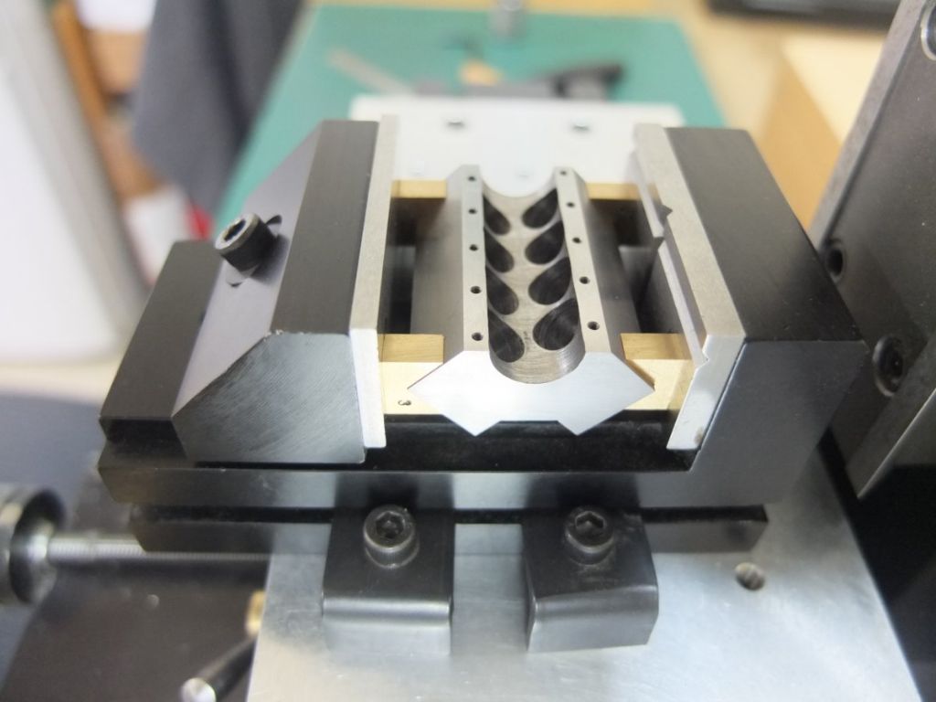
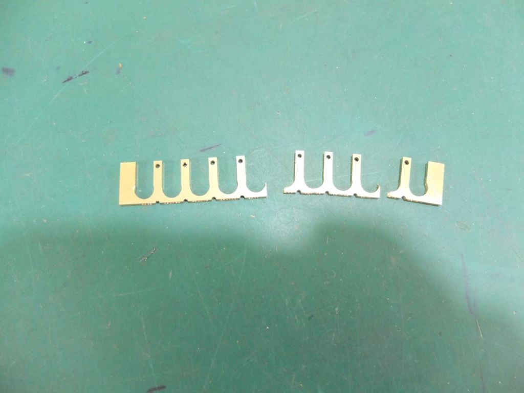
Here is the block, ready to be milled. Note the miniature brass V-blocks – very handy things. You can see they are numbered. This is to ensure repeatability when using them with a 4-jaw.
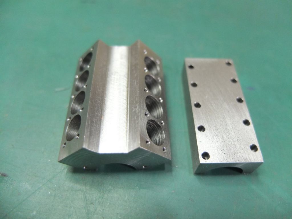
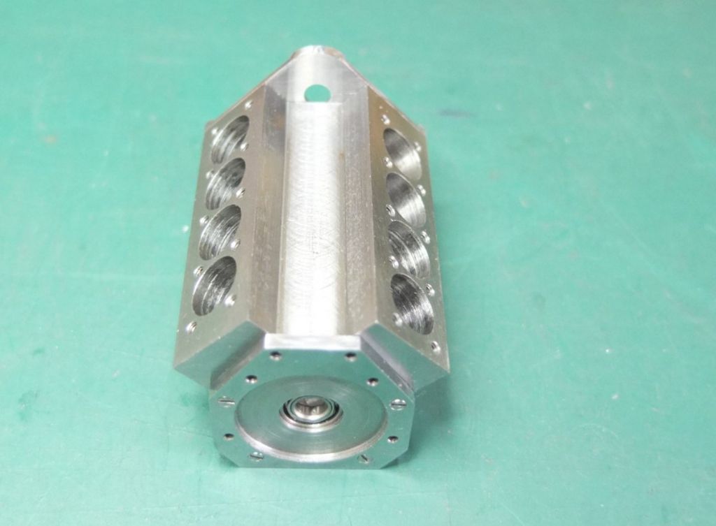
And here they are completed. The block now weighs 60g. The initial square blank weighed 370g. That might not sound a lot of swarf to you guys with big-boy’s lathes, but it made a mess of the kitchen table with my Sherline.
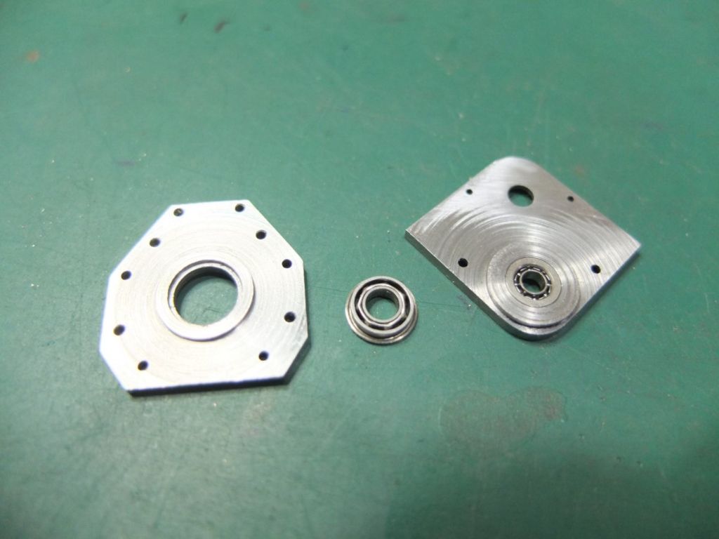
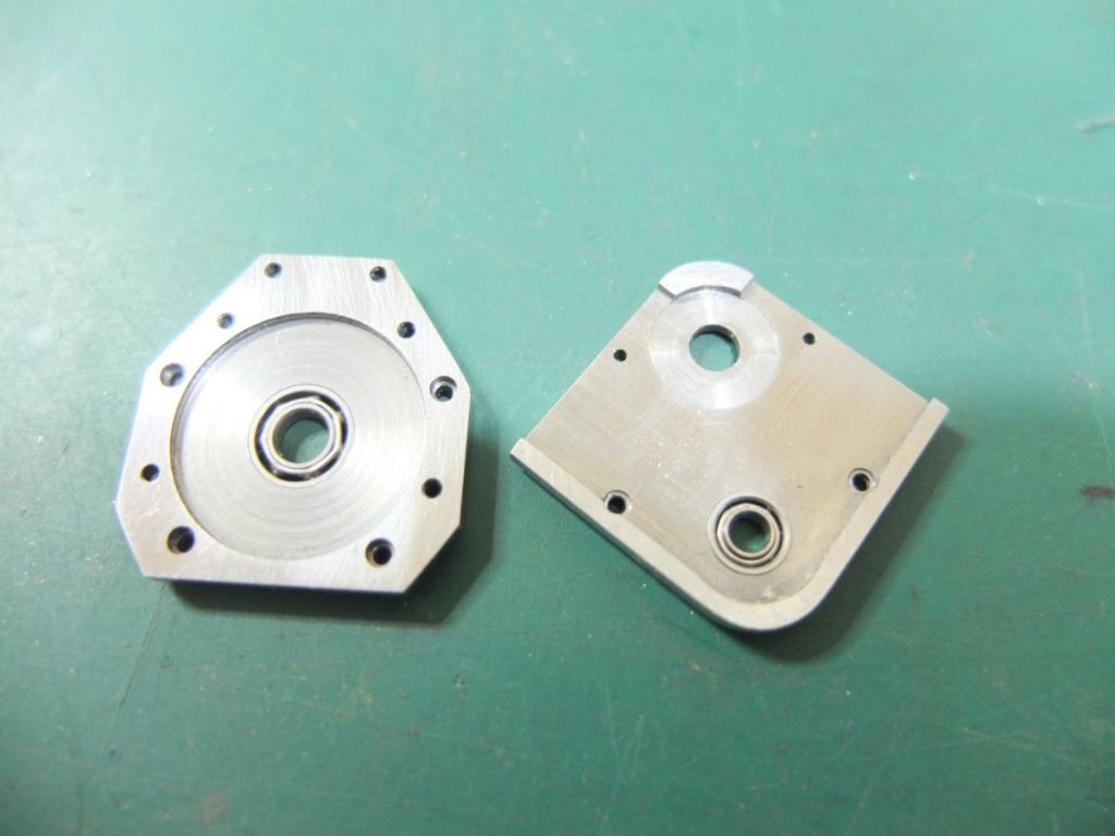
I made some endplates from 1/8” mild steel flat bar. These hold flanged bearings for the crankshaft, 4mm at the gearbox end and 3mm at the cam-drive end. There is raised boss on the back of both which are a snug fit into the crankshaft bore to keep thing nice and true.
The one on the left will house the flywheel and the one on the right, the cam gear train.
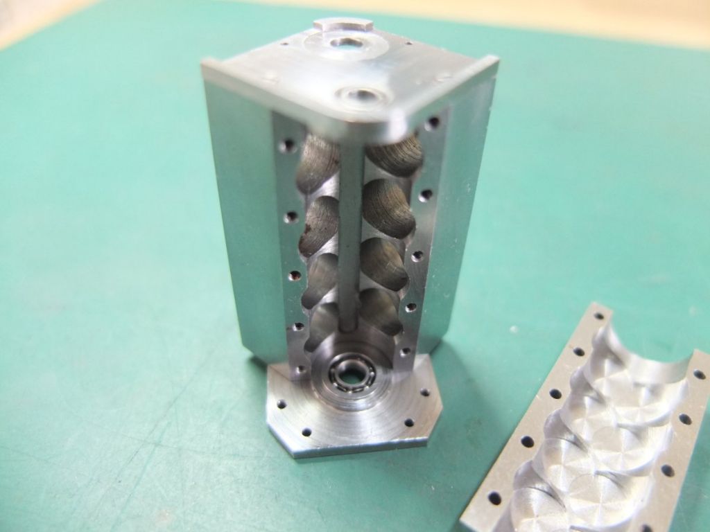
The sump and block were drilled and tapped 12BA to secure the endplates and everything was assembled.
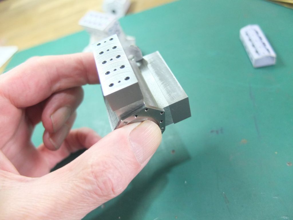
I then fly-cut some steel to size for the cylinder head blanks and drilled and counterbored to suit the block. All in all, I had to tap 30 blind holes to M1.6 in the block. A bit scary.
I also cut to size blanks for the cam carriers. They can just be seen in the background.
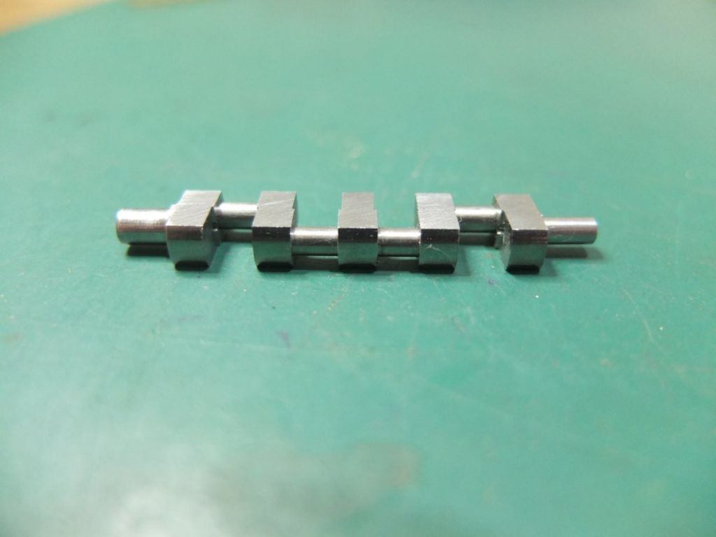
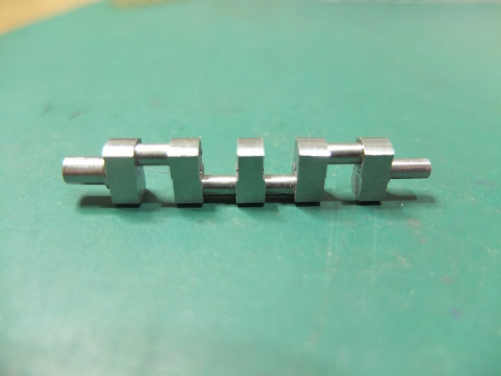
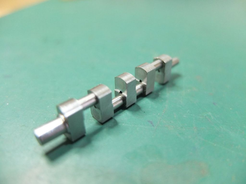
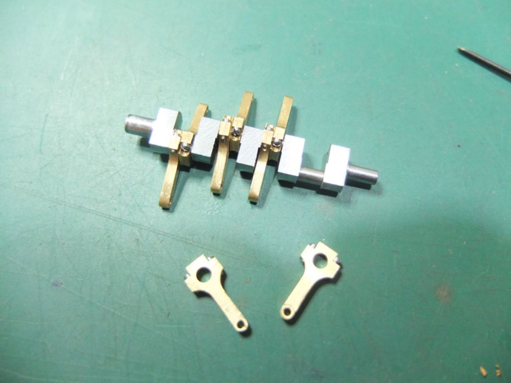
The flat-plane crank is assembled from EN1A webs and 3mm silver steel journals.
The assembly was a tight friction fit then drilled, countersunk, pinned and riveted. 1mm mild steel pins were peened into the countersink then filed and polished over to render invisible.
The unwanted journals were then sawn out and the gaps between webs cleaned up on the mill.
When I was a young lad working in a local motorcycle shop I took a phone call from a gentleman who wanted us to collect his son's field bike to sort out the non-running engine. Being an 'expert' I asked if he had checked if the petrol was turned on and if there was a spark – turned out I was talking to Keith Duckworth… Doh!
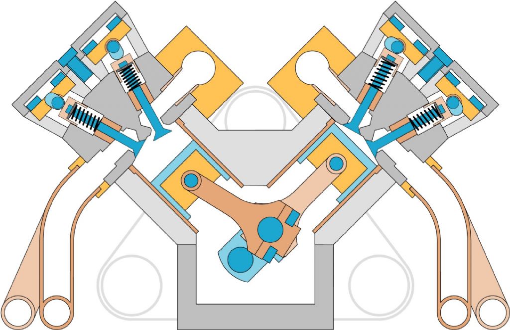
Here is a drawing of a cross-section through the cylinders. It is sort of colour coded. Grey is EN3B, light blue EN1A, dark blue are screws and silver steel and orange or brown are brass except for the exhaust headers which are copper tube.
The air is fed from the two brass vessels (plenums?) in the vee.
This a hypothetical cross-section as there are 4 valves per cylinder and the banks are staggered.
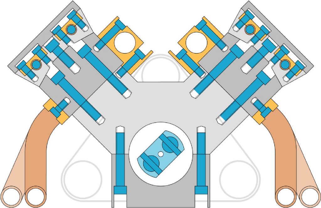
Here is another cross-section, this time between the cylinders.
When designing this, I had a bit of a headache making sure the screws didn't clash with anything or each other. The problem is, even using the smallest economically available, the screws are grossly over scale.
I'm using M1.6 allen screws with the head turned down to 2.35mm to hold the sump, block, heads and cam carriers together.
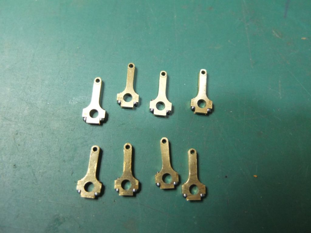
12 BA cheesehead screws with the head turned down to 1.95mm for the con rods, exhaust and inlet manifolds and also the cam covers.
I will use either M1.0 or 14 BA cheesehead to secure the cam shaft. I want to find a good quality supply of steel screws first(non-stainless, I'll be blueing them). When I find them, I'll buy the appropriate taps. If anyone has any advice on this, I would be grateful.
…I will use either M1.0 or 14 BA cheesehead to secure the cam shaft. I want to find a good quality supply of steel screws first(non-stainless, I'll be blueing them). When I find them, I'll buy the appropriate taps. If anyone has any advice on this, I would be grateful…
Steve
EKP SUPPLIES and BA-BOLTS are two suppliers that list plain steel cheesehead down to 14BA.. ..others might too, those just sprang to mind..
I have and do use EKP, satisfactory fit & finish on the larger BA stuff I've had – I've seen BA-B recommended before, so probably fine as well.. ..there may be others..
“It will be a 2-stroke running on air (or CO2?) with a bore of 7.2mm and a stroke of 5mm.”
Was this a typo Steve? or am I missing something.
Mike
No typo. By 2 stroke, I meant a simple expansion engine with 2 cycles, in and out.
I suspect I am not using the right terminology.
I have read your description again and realise what you said, I was locked into internal combustion think. It’s looking great so far, it will be nice to see it running when finished.
EKP SUPPLIES and BA-BOLTS are two suppliers that list plain steel cheesehead down to 14BA.. ..others might too, those just sprang to mind..
I have and do use EKP, satisfactory fit & finish on the larger BA stuff I've had – I've seen BA-B recommended before, so probably fine as well.. ..there may be others..
Thank you, I've just checked them out. It seems that 14BA screws are more easily available than M1 so I'll probably go for that. A finer thread too – M1 is pretty coarse at 0.25 pitch. I can single point thread down too 0.25 pitch on my Sherline lathe but I need at least 60 screws!
14 BA taps are quite pricy though. I might have to redesign a few bits so there are no blind holes, then I can get away with a single taper tap.
All the ones I've seen seem to be around the same price, £15 each so I suspect they are all the same manufacturer. There can't be too many companies making 14 BA taps! Has anybody got any recommendations?
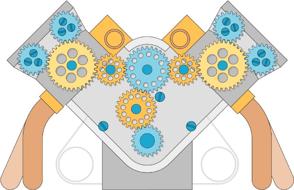
This is the gear train for the cams. The camshafts rotate counter to the crank. The blue gears (EN1A) are driven or drive and the orange/yellow (brass/nickel silver) ones idle.
This is quite a bit simpler than the full-size engine, which has compound gears, but it does resemble it.
The gears are Mod 0.3 as I have a set of involute cutters. It would work in Mod 0.4 or 0.5 as well.
This is part of the build I'm looking forward to most.
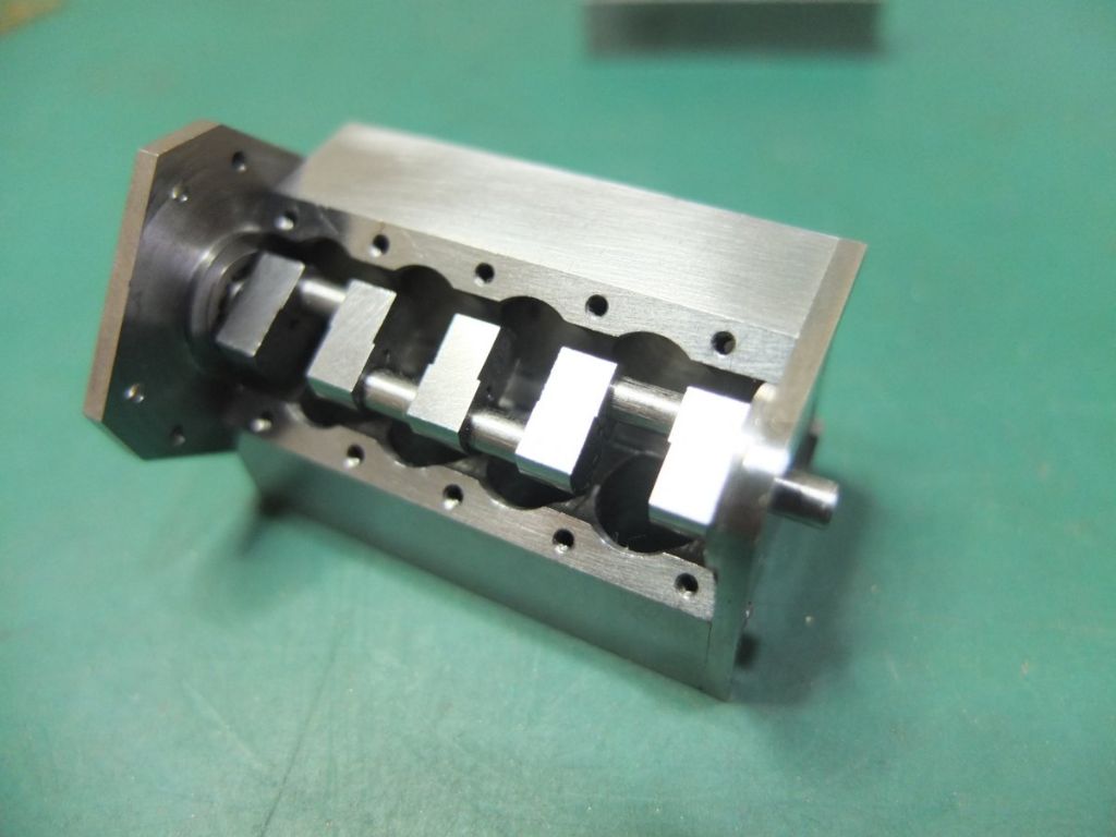
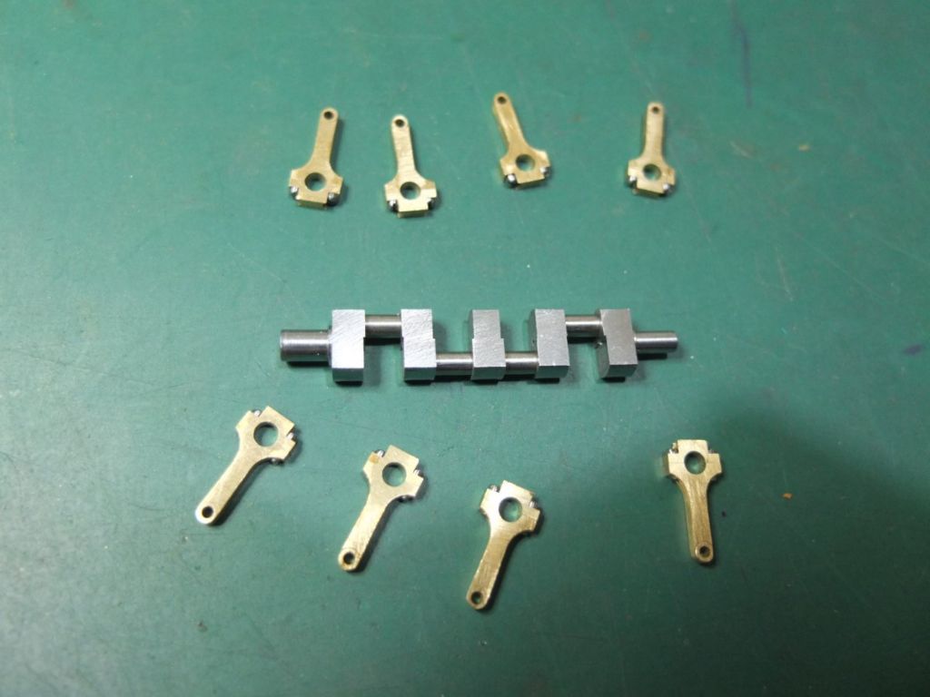
Before I went any further, I thought I'd test fit them on the crank.
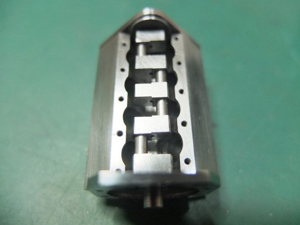
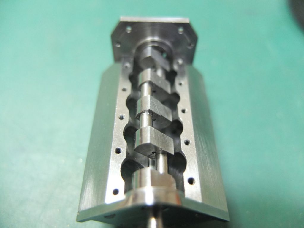
A fiddly job attaching these but everything fits and moves nicely with minimum play. The middle one at the front looks like it isn't straight but that's the camera angle.
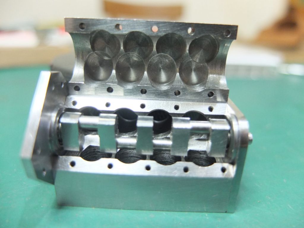
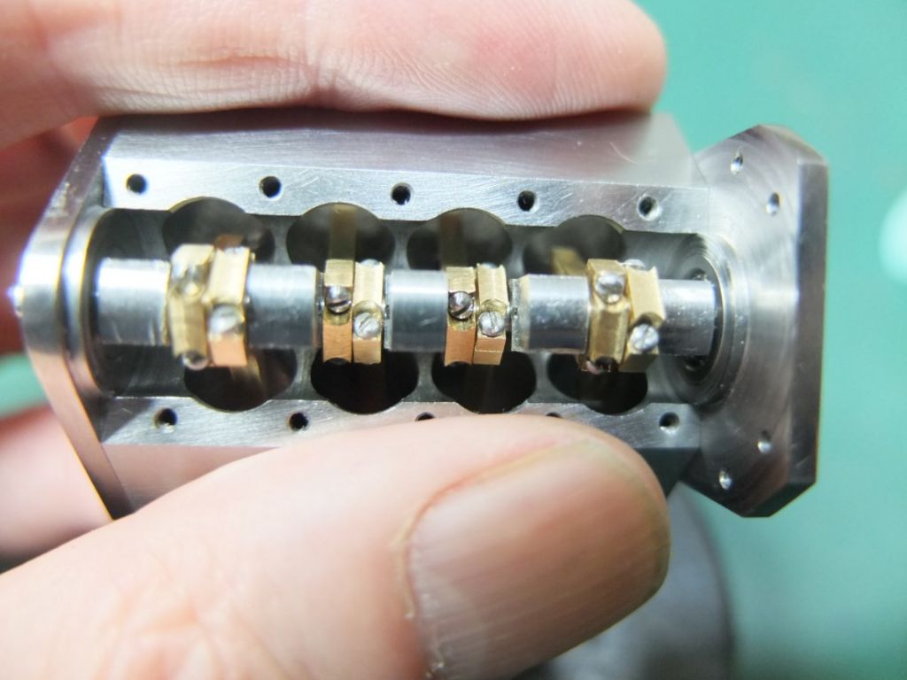
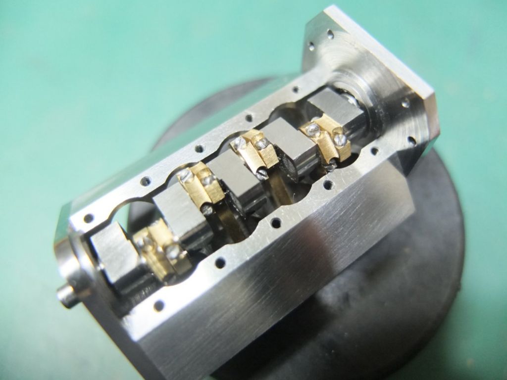
I then tried the whole assembly in its bearings in the block.
The conrods do foul the block in parts but this is because they are no liners or pistons in yet so the rods are rotating more than intended.
I've got to say that it doesn't look like the bottom end of a racing engine – more like some late Victorian marine engine. The thickness of the conrods is massively overscale. This is a consequence of using the smallest screws I had.
Even then, I had to turn down the heads to 1.8mm and dome them for clearance.
This is also the reason why there is only two bearings. There just wasn't space for other journals.
I'm happy to answer any questions or receive any criticism.