Copper boiler plate flanging, or not?

Advert

Copper boiler plate flanging, or not?

Home Forums Workshop Techniques Copper boiler plate flanging, or not?

Viewing 25 posts - 51 through 75 (of 132 total)
  • Author
    Posts
  • #489970
    Bob Worsley
    Participant
      @bobworsley31976

      Should I apologise for this post? Getting some good comments.

      Sorry, yes, did miss that and 15% is significant. Here comes the lack of any hands on experience. Might be flanging after all!

      the 5 thou came from all the boiler books and other articles I have been reading. They all seemed to think that 5 thou was critical, so I followed on. My point about SM chips is with hand soldering, not automatic.

      Just stir it up even more, is TIG welding of copper for pressure vessels? The above boiler books say that carbon arc heating is simply not on, but what is a TIG torch than similar in temperature to a carbon arc? There is no control over the temperature of the arc.

      I don't really understand the problem with girder stays on the top of the firebox either.

      Advert
      #489972
      JasonB
      Moderator
        @jasonb

        Yes TIG boilers are for use under pressure. Some are fully tig welded others may just weld up a rolled boiler barrel and then silver solder the rest or main joints welded and bushes etc soldered in.

        I expect most of the books were written before the advent of TIG, current and electrode size can affect the amount of heat going into the job giving some control in the right hands (not mine)

        Edited By JasonB on 10/08/2020 13:08:13

        #489974
        Nick Wheeler
        Participant
          @nickwheeler
          Posted by Bob Worsley on 10/08/2020 12:58:38:Just stir it up even more, is TIG welding of copper for pressure vessels? The above boiler books say that carbon arc heating is simply not on, but what is a TIG torch than similar in temperature to a carbon arc? There is no control over the temperature of the arc.

          I don't really understand the problem with girder stays on the top of the firebox either.

          A TIG torch surrounds the weld with inert shielding gas.

          #489982
          Paul Kemp
          Participant
            @paulkemp46892

            Acceptable TIG welds on copper for pressure vessels require low arsenic copper. Controlling the temperature of the 'job' is done by the settings on the machine and the wielding of the torch. As Jason said the TIG process per se has come a long way since a lot of the books were written, the most basic variants are AC and DC but getting more advanced you can adjust frequency and other parameters to suit the job in hand.

            Paul.

            #489983
            Paul Kemp
            Participant
              @paulkemp46892
              Posted by duncan webster on 10/08/2020 00:48:24:

              Ah but if we did that, over zealous boiler inspectors would start applying stuff relevant only to steel to copper boilers.

              If they did that they should be struck off! There is already an opportunity for that within the test code. There is also an opportunity within the test code where it requires supporting calculations to be presented for a non published or pre approved design for over zealous inspectors to make up their own requirements because there is not an accepted or referenced underpinning COP or standard!

              Paul.

              #490916
              JasonB
              Moderator
                @jasonb

                Posted by Bob Worsley In another thread on 16/08/2020 10:50:08:

                Anyone building any model from plans gets a collection of sheets of paper, no calculations to be seen about boiler safety. In fact my Thetford Town drawings assume you are going to rivet it, with brazing as a last option if it leaks.

                If a line contact joint is considered to be perfectly ok, then why not line joint all the other joints? I would guess that certainly wouldn't be acceptable to any inspector. Why not? It is how a steel boiler is made, never flange them. So there must be a fundamental difference between silver soldering and arc welding. One is done by a trained professional?

                There was a comment in an old ME about where do all the models made go to? Must be tens of thousands. And since the boiler is the first thing made with a traction engine, how many are made, leak, and the person gives up, 50%? How many Minnie boiler kits have Reeves sold over the last 50 years?


                And yes, the boiler does look good, well done. It amazes me just how well the pickle cleans the copper, lovely.


                And yes, again, these are my opinions.


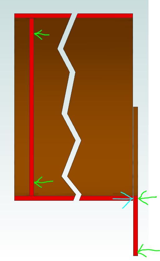
                As mentioned byJeff in the other thread the way the throatplate/barrel joint is constructed would be quite different to say the smokebox tubeplate/barrel if the tubeplate were not flanged.

                If you look at this basic section through the boiler you can see that the pressure shown in green arrows will push the throatplate against the end of the barrel which will greatly reduce the load on the joint as the end of the barrel adds support light blue arrow. The suggested use of a higher melting point solder will also produce a larger filler thus adding strength to the joint.

                Compare that to an unflanged tubeplate where there is just the empty smokebox on the outside so no additional support for tubeplate so joint has to resits all the loads.

                minnie joints.jpg

                As for steel boilers the weld prep is very important as it gives a far wider joint area that you would get if it were just plate to tube and the fillet will almost double the area. A throatplate to barrel joint would also probably be welded from both sides.


                Edited By JasonB on 16/08/2020 14:08:42

                #491030
                Paul Kemp
                Participant
                  @paulkemp46892

                  Bob,

                  I think you have been reading too many books! You cannot make comparisons between welded steel joint design and silver soldered copper. 2 completely and fundamentally different processes with their own advantages and disadvantages in two completely different materials. I haven't seen the drawings for TT or any constructional advice but I very much doubt there is any serious recommendation to rivet and braze if it leaks. I would think with the age of it the boiler was designed as rivetted and soft solder caulked, the rivets take the stress the solder bungs up the leaks. It's not a method condoned now for new boilers but properly done there is nothing wrong with it and there are still a fair number in service.

                  There were over 50 Ruston Proctor kits sold by Winson and Modelworks, they came with a ready made and certificated boiler but I haven't seen 50 chuffing round! A lot of part complete models sold are nowhere near the boiler stage, sometimes without motion work completed even so I don't think leaky boilers are the real reason for non completion.

                  Paul.

                  #491133
                  Bob Worsley
                  Participant
                    @bobworsley31976

                    Yes, these threads do seem to take on a life of their own!

                    Jason, you are utterly wrong with your drawing above. The pressure is internal, and this pressure acts on the tubeplate and backhead to blow the ends of the boiler apart, the internal pressure by the firebox front and boiler are irrelevant.

                    More reading, found some interesting comments in ME 3672 1-14 Jan 1982 p48/49 about throat plate flanges. I read the very old thread about posting photos in the forum, didn't really understand it. Seems very complicated and I refuse to use facebook or any other of these data thieving sites.

                    Also about longitudinal stays in other copies with writing by Martin Evans about why he thinks they are rubbish and replaces them with a chunk of copper across the smoke box plate and back plate.

                    I agree that TT with a riveted boiler is 'interesting', Reeves did include a newer drawing with it brazed. These drawings are near 40 years old, bought, never made, sold to me. One thing is clear, just how much better the quality of the castings is then to now. Some of the newer aluminium castings are basically rubbish.

                    #491135
                    JasonB
                    Moderator
                      @jasonb
                      Posted by Bob Worsley on 17/08/2020 17:12:53:


                      Jason, you are utterly wrong with your drawing above. The pressure is internal, and this pressure acts on the tubeplate and backhead to blow the ends of the boiler apart, the internal pressure by the firebox front and boiler are irrelevant.

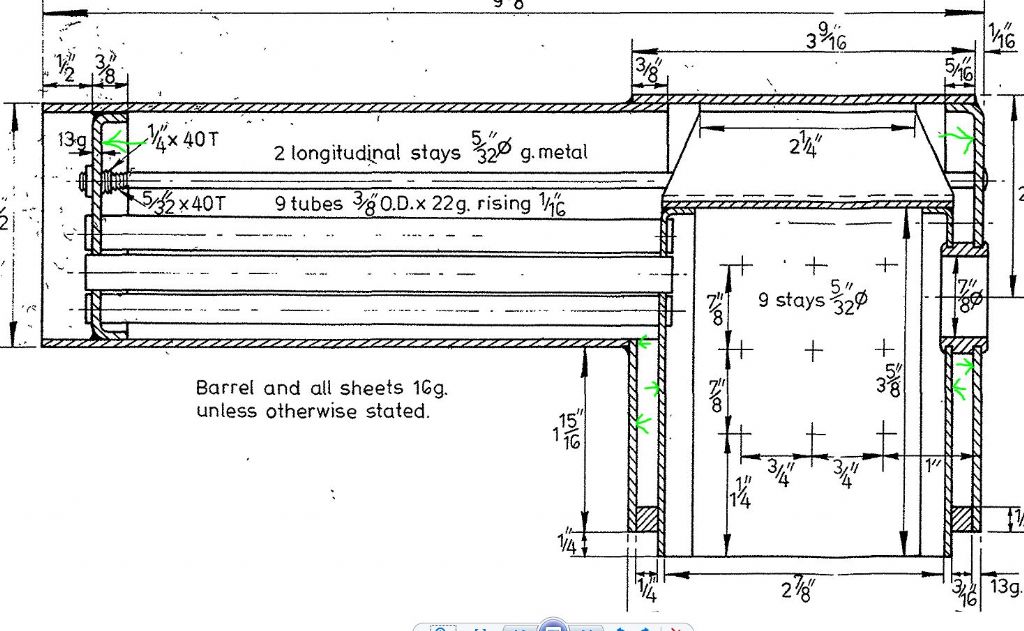
                      Sorry Bob but you are obviously not following my drawing.

                      Here are the same green arrows on the actual minnie drawingare showing the pressure pushing the plates outwards

                      minnie pressure.jpg

                      Edited By JasonB on 17/08/2020 17:24:10

                      Edited By JasonB on 17/08/2020 17:37:03

                      #491142
                      Nick Clarke 3
                      Participant
                        @nickclarke3
                        Posted by Bob Worsley on 17/08/2020 17:12:53:

                        Also about longitudinal stays in other copies with writing by Martin Evans about why he thinks they are rubbish and replaces them with a chunk of copper across the smoke box plate and back plate.

                        I agree that TT with a riveted boiler is 'interesting', Reeves did include a newer drawing with it brazed. These drawings are near 40 years old, bought, never made, sold to me. One thing is clear, just how much better the quality of the castings is then to now. Some of the newer aluminium castings are basically rubbish.

                        If you have a smokebox tubeplate or backhead the failure mode will be for it to bulge and then 'peel' the flanged silver soldered seam apart. if you can prevent the bulge the silver soldered seam will be in pure shear and I expect the joint will be far stronger under these conditions.

                        How do you stop the plates bulging? – either with a longitudinal stay or stays or with a stay soldered on – as I believe was done in some traction engines .

                        #491144
                        duncan webster 1
                        Participant
                          @duncanwebster1

                          The most highly stressed joint in a boiler is usually the longitudinal barrel seam (if there is one, lots are made of tube).

                          The 2 ends are held together not only by the barrel, but also by a host of stays and tubes, even if there were none the longitudinal stress would only be half the hoop. As Jason says the throatplate/barrel joint is in compression if done as per Jason's drawing.

                          Rivetted and soft soldered boilers are a thing of the past. Yes they could be made safe, but one mistake with water level and your boiler was ruined.

                          #491156
                          SillyOldDuffer
                          Moderator
                            @sillyoldduffer

                            Rather than decode good and indifferent from old Model Engineer magazines, Bob could try his hand with CAD and Finite Element Analysis.

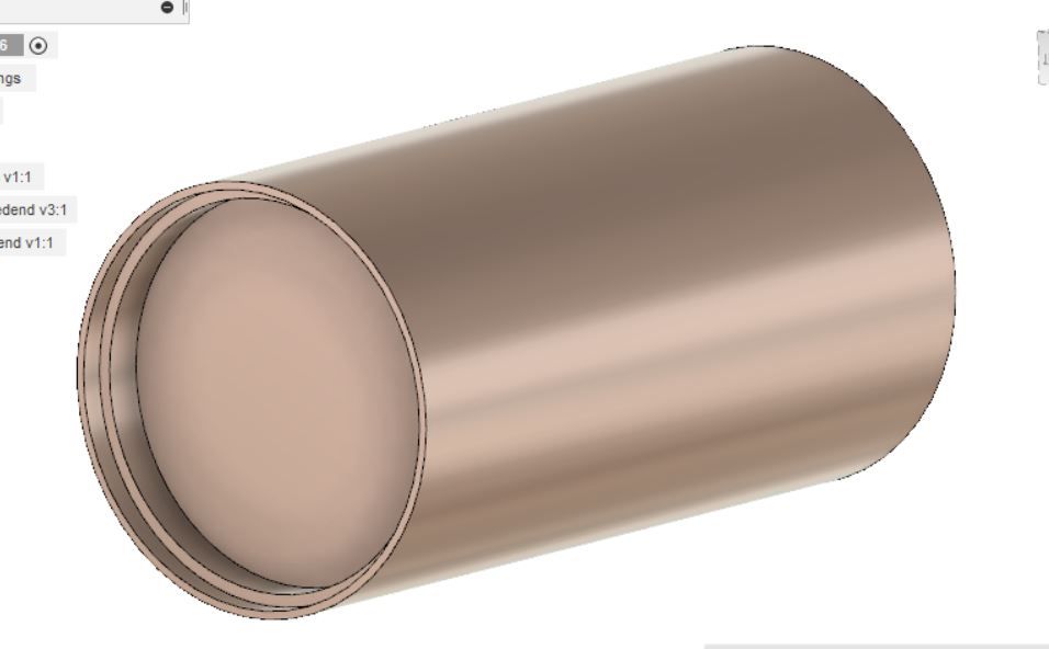
                            Just a taste as I've likely made mistakes setting up the model, buf here's a simple cylinder boiler made of Copper with a flat flanged end disc and no stays modelled in Fusion360:

                            boiler.jpg

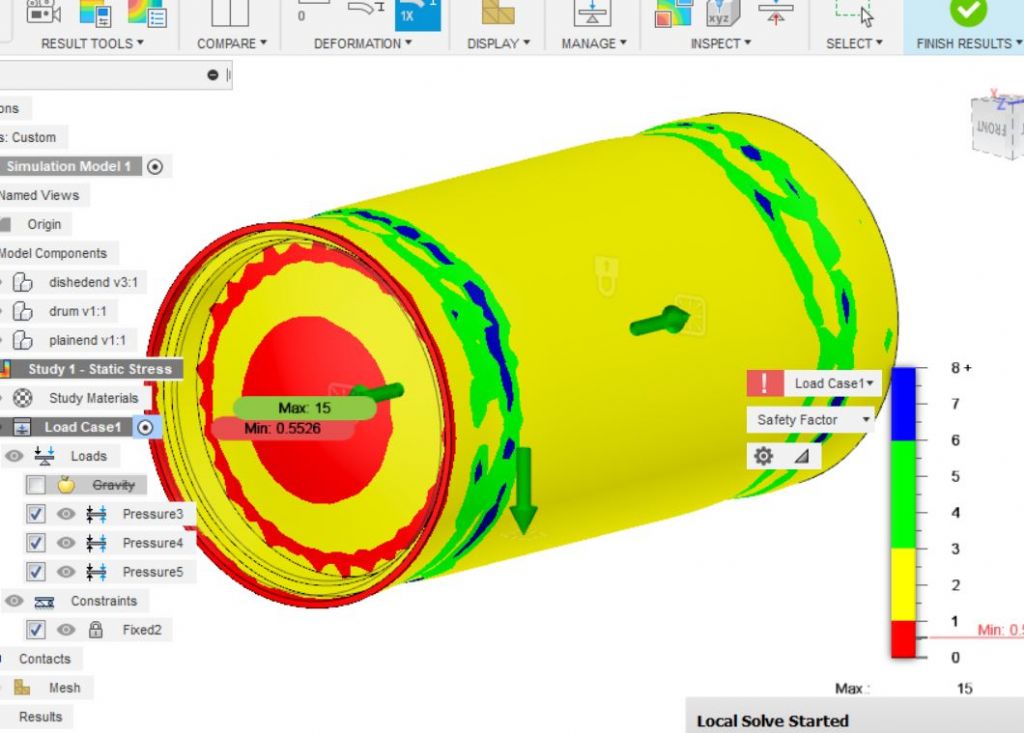
                            Running FEA to identify safety concerns draws a colour map with the weakest areas in red. The internal pressure is 0.7MPa, about 100psi.

                            safety.jpg

                            A few concerns with this design, notably the disc is red in the centre. Needs strengthening by dishing the end, or fitting an internal stay.

                            Generally the boiler is yellow – meaning the safety factor is low. The strengthening effect of the dished end can be seen as green/blue rings. The outer red ring on the disc shows it's highly stressed at he joint; this might be fixed by a centre stay.

                            My feeling with copper boilers is they're as good as they can be. Whilst FEA might identify a clever new design, I suggest the old guys had established 'best practice' by about 1955. They'd been experimenting for over a century and were on solid ground by then.

                            Dave

                            Edited By SillyOldDuffer on 17/08/2020 21:03:30

                            #491165
                            Roger Best
                            Participant
                              @rogerbest89007

                              As an owner of numerous toy engines I can confirm that Duncan is right about " one mistake with water level and your boiler was ruined".

                              #491174
                              Jeff Dayman
                              Participant
                                @jeffdayman43397

                                I would urge caution interpreting FEA results in sheetmetal assemblies (like boilers). Depending on metal and thickness vs area the stress may be non-linear as ANY deformation of the sheet / tube occurs. For work like this in industry I have hired professional FEA analysts several times, to be sure the construction is safe at the working pressures expected. Non linear FEA is very complex and expensive, if accurate results are needed. Do not assume the behaviour of the sheetmetal will be linear. Free FEA as found in CAD packages is usually limited to linear analysis- adequate for many things, but not for sheetmetal that is deforming.

                                #491179
                                Zan
                                Participant
                                  @zan

                                  Bob, look at the drawing at the end of page 3 of this thread

                                  Let us assume you use Your 6 mm plates for the firebox not the 2.5mm as specified and 8 mm for the blackhead in order to Maintain the 1.5mm setback beyond the wrapper

                                  your comment about reducing the water space is your initial post is frankly daft It’s already very narrow , keeping the dimensions the same with a solid back head would leave 1.5 mm  Not really enough…….so the firebox back will have to be moved by 6 mm

                                  so in total the firebox will loose 3.5 at each end for the thicker plates, and another 6 as shown above I.e total of 13mm or 1/2” In an already small firebox. Resulting in a reduction of 18% grate area. There will also be a reduction in the overall water capacity don’t forget the overall dimensions of the boiler is from the prototype so it’s fixed

                                  getting most of the plates to fit with your small gap is not so difficult as the copper is extremely workable when properly annealed. Flagging boiler plates isa fascinating exercise on its own As is the process of producing a short bit of seamless tube from flat plate ( raise it and cut the end off even perhaps resulting in thicker wall t than the original sheet )

                                  many many boilers have been produced with flanged plates. We havnt been doing it wrong for the last. hundred or so  years…. don’t  be the soldier who is in step, while the rest of us in the parade are out

                                  Edited By Zan on 18/08/2020 00:22:19

                                  Edited By Zan on 18/08/2020 00:23:58

                                  #491198
                                  SillyOldDuffer
                                  Moderator
                                    @sillyoldduffer
                                    Posted by Jeff Dayman on 17/08/2020 22:35:41:

                                    I would urge caution interpreting FEA results in sheetmetal assemblies (like boilers). Depending on metal and thickness vs area the stress may be non-linear as ANY deformation of the sheet / tube occurs. For work like this in industry I have hired professional FEA analysts several times, to be sure the construction is safe at the working pressures expected. Non linear FEA is very complex and expensive, if accurate results are needed. Do not assume the behaviour of the sheetmetal will be linear. Free FEA as found in CAD packages is usually limited to linear analysis- adequate for many things, but not for sheetmetal that is deforming.

                                    Can't disagree with any of that! My example is a Fusion 360 local linear analysis (ie sums done on my computer), rather than Autodesk's cloud solver, for which credits are required. I don't know what extras the cloud solver provides, but assume the local solver is more basic.

                                    Like all models, it's good to be mindful of their limitations. Scaled up Bumble-Bees can't fly etc. But I think FEA will indicate stress problems rather better than back of an envelope and other unquantified approaches. I don't think it's possible to apply modern technique to small boilers without doing the engineering. FEA, slide-rule, and testing prototypes. The problem with prototypes is how many need to be made to get an acceptable answer; expensive of time and money, so it pays to eliminate obvious mistakes on paper or with a computer.

                                    First time I thought about copper boilers and model locomotives, I assumed they would be primitive and easy to improve. Silly me! Looking deeper I decided copper's properties make it top choice for home-made boilers. It's strong enough and well-behaved whilst being brazed or soldered, both processes making fixable joints. Doesn't develop nasty faults due to internal corrosion. If the boiler fails under pressure, Copper tears slowly rather than disintegrating explosively. Easier for inspectors to detect faults in copper boilers, for example quite difficult to confirm welds in a steel boiler really are sound throughout. Add a century plus of practical experience, and existing copper designs have to be a good bet. They can be built safely by chaps with moderate skills and experience, and professional examples will be even better. High-pressure boilers should be made from steel, but getting the technology right is difficult, and I'm not sure a home-made loco running at 300 or 400 psi would be welcome at many clubs.  And certainly not if I'd made it!

                                    Dave

                                    Edited By SillyOldDuffer on 18/08/2020 09:41:38

                                    #491202
                                    JasonB
                                    Moderator
                                      @jasonb

                                      What I find a bit strange on Dave's image is that the very end of the barrel is red yet it is outside the joint and under no boiler pressure. It would also be interesting to see how things change if the flange were in the usual position of facing inwards rather than how Dave has shown it.

                                      #491214
                                      Roger Best
                                      Participant
                                        @rogerbest89007

                                        Is the edge used to fix the model in space?

                                        #491222
                                        nigel jones 5
                                        Participant
                                          @nigeljones5

                                          Interestingly the Australian Fed who produce a far more detailed set of regulations than the UK conducted testing with full flange, hardly any flange and no flange at all (simple yube with end plates). All three were perfect under test conditions with no distortion between them. They published their findings…ive got it somewhere! My boilers employ a minimum of 3 x thickness to flange ratio and are turned to fit. Ive never had a boiler returned for a defective joint and ive made hundreds.

                                          #491250
                                          Dave Smith 14
                                          Participant
                                            @davesmith14

                                            SOD

                                            The cloud based F360 will not be significantly different if at all. For non linear analysis you need specific software. The majority of industry including Aerospace uses linear analysis for the bulk of its work. I was involved in thin sheet structures and we only used non linear analysis where the effect of birdstrike was required and we were using much lower reserve factors than many industries typically 15% margins on proof stress, ie providing our reserve factor was above 1.15 we were happy. If fatigue was the issue then the reserve factors goes up because your stress limits come down. IMO providing you keep the stress well within the proof stress and fatigue limits then a linear analysis is quite adequate. If you work on a reserve of > 4 you are unlikely to get a problem. By the way I did an FEA on a steel Highlander boiler a couple of years ago for a guy on this forum. Interesting exercise. With a steel boiler the stressing is easy, with plenty of material properties data, the main issue is getting it built and inspected properly.

                                            Dave

                                            #491256
                                            SillyOldDuffer
                                            Moderator
                                              @sillyoldduffer
                                              Posted by JasonB on 18/08/2020 10:07:27:

                                              What I find a bit strange on Dave's image is that the very end of the barrel is red yet it is outside the joint and under no boiler pressure. It would also be interesting to see how things change if the flange were in the usual position of facing inwards rather than how Dave has shown it.

                                              Probably because I fully constrained the barrel there in order to get the solver to run. In effect I told the model the boiler is fixed around it's rim to an infinitely strong immovable object. So the barrel expanding under internal pressure stresses a non-existent joint.

                                              I don't think the imperfection invalidates the model, but wouldn't bet the farm on it. My understanding of FEA is more than a little incomplete!

                                              Dave

                                              #491265
                                              Roger Best
                                              Participant
                                                @rogerbest89007

                                                angelthumbs up

                                                #491272
                                                Phil H1
                                                Participant
                                                  @philh196021

                                                  Can I ask a question about Minnie please? It has a remarkably small boiler (page 3) – hence the name I guess but what can it realistically do? e.g., on a really nice flat surface, can it pull the driver or do you run it like the little Mamod traction engines using a long control rod?

                                                  Phil H

                                                  #491277
                                                  SillyOldDuffer
                                                  Moderator
                                                    @sillyoldduffer

                                                    Just for fun, but this model features corrections to my original plain Boiler plus a flanged disc at one end and a plain disc at the other for comparison.

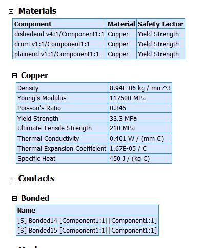
                                                    The model is now 3mm Copper throughout, and the pressure is 0.7MPa (bit over 100psi). Cylinder 50mm internal diameter by 100mm:

                                                    boilerphysicaldata.jpg

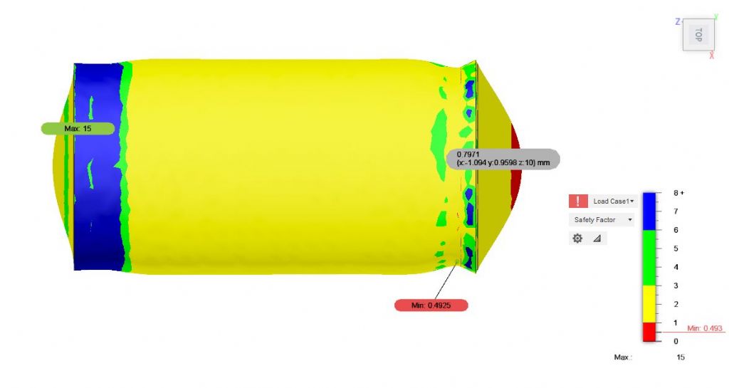
                                                    Safety Factor is x6 and the deformation is x2 (ie exaggerated to highlight movement)

                                                    Top view:

                                                    boilerdishnottop.jpg

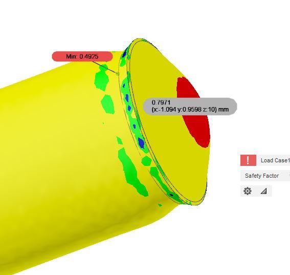
                                                    No red at the flanged end, and lots of reassuring blue where the drum is reinforced by the flange. The disc bulges out, as does the drum. More interesting at the other end where the unreinforced drum swages inwards while the plain disc has a pronounced outward bulge with a red bullseye. FEA suggests the weakest point is the very thin red line running around the drum. (Labelled Min 0.4925) The bullseye is roughly half as stressed (0.7971 at the sample point).

                                                    boilerflatend.jpg

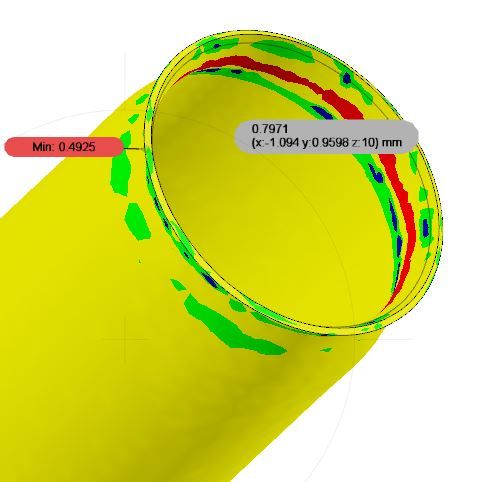
                                                    Making the plain disc invisible reveals more obvious stress at the danger point inside the boiler:

                                                    boilerflatendinside.jpg

                                                    As expected FEA highlights the weakest point on my mock-up as the joint between the plain disc and the drum. Conversely, the flanged joint at the other end scores as the strongest part of the design.

                                                    Not to be taken too seriously!

                                                    Dave

                                                    #491282
                                                    Bob Worsley
                                                    Participant
                                                      @bobworsley31976

                                                      Jason, you are correct, the throatplate is in compression against the barrel. I had assumed that the throatplate was curved to fit on the outside of the barrel. This is an insignificant difference that could have ramifications? Not noticed that the instructions were to position it as drawn. The Allchin is drawn similarly.

                                                      Duncan, the most highly stressed joint in a static engine is the longitudinal barrel seam, but how does this change if you are driving it over rough ground, or even a road?

                                                      FEA! Count me out. But why does the barrel show patches of blue and green? The whole shell is pressurised to the same pressure, so variations like that show something os wrong with the calculations?

                                                      Zan, narrowing the firebox rather than the water spaces is obviously the way to go, get no water movement at all in 1.5mm. I don't dispute that many, tens of thousands, of boilers have been made, it was the question in the ME I was echoing, where are they? I rather suspect that more get scrapped than run an engine. Nothing to back it up, but the always repeated how to stop leaks with every design. One was to put some bran, or something, inside and pressurise it whilst shaking.

                                                      I don't wish to take on the whole ME community about boilers, of which I have made none, but they are expensive in materials, solder, gas, time and everything else and didn't want a dud. I decided to make a couple of Minnie boilers, simply because they were small and would cost around £350 each, before trying the BB boiler, £1000+?

                                                      SoD makes the statement that copper tears slowly. From where does he get that fact? Used to have lots of The Engineer, and read the explosion reports, and the size of the area that the bits were thrown. Iron is much stronger than copper yet it didn't seem to stop an explosive explosion. Go and read the srticle about the failing boilers made with Silfos, weeping joints, would have been interesting to have pressurised them until they failed.

                                                    Viewing 25 posts - 51 through 75 (of 132 total)
                                                    • Please log in to reply to this topic. Registering is free and easy using the links on the menu at the top of this page.

                                                    Advert

                                                    Latest Replies

                                                    Home Forums Workshop Techniques Topics

                                                    Viewing 25 topics - 1 through 25 (of 25 total)
                                                    Viewing 25 topics - 1 through 25 (of 25 total)

                                                    View full reply list.

                                                    Advert

                                                    Newsletter Sign-up