Coping with voltage spikes

Advert

Coping with voltage spikes

Home Forums Electronics in the Workshop Coping with voltage spikes

Viewing 25 posts - 76 through 100 (of 151 total)
  • Author
    Posts
  • #491103
    Robert Atkinson 2
    Participant
      @robertatkinson2

      Hi Tim,

      Bit OT but it has come up – legality of LED bulbs. This does NOT apply to your 1929 Vehicle, but the regulations are clear, all required exterior lights on a modern car (post 1985 at least, some regs apply earlier) must be approved and "E" marked. The "E" mark confirms that the light meets the required standards. These standards include that REPLACEABLE lamps (bulbs / filaments) must also meet certain standards (ECE) and be E marked. There are currently NO ECE standards for replacable LED lamps or LED alternatives to filament lamps. If it is not E marked you can't use it for exterior lighting on a modern car. The odd exception is the reversing light.
      So How come some new cars have LED lights? This is because the whole light assembly has been tested, approved and E marked and there are no replacable lamps, bulbs or LEDs. You can for instance buy an LED replacement for a sealled beam uit because it is a complete light. LED DRLs are also available.

      Back to spikes,

      A resistor zener suppressor has been posted to Tim today

      led-supp.jpg

      180 ohm resistor and 12 V 1 W zener (found a 1 W before a 500 mW) with a bit of Kapton tape insulaion so you can see how it's wired. I also included a 5 mm "12 V 20 mA" LED that made up this has a 470 ohm series resistor and draws 19 mA at 12V. I noted tha while the catalog listed the LED as 20 mA, the data sheet says 20 mA is absolute maximum. So this is righ on the edge. Conneced to the suppressor circuit it survived 28V input (19 mA through LED) though the resistor and zener run hot at that. It also survived 12V negative for short duration (resistor is overloaded by 20 % at this).

      I'm confident this will fix the issue.

      Robert G8RPI.

      Advert
      #491107
      Maurice Taylor
      Participant
        @mauricetaylor82093


        Hi,

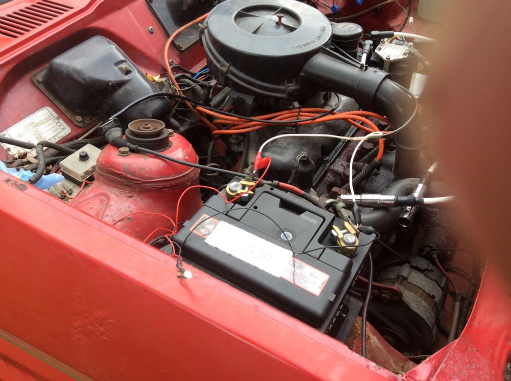
        I have just tested my clear Led with 820 ohm resistor in series on my 40 year old coil and distributer ignition Fiesta.

        1 Connected Led to battery, Led lit.

        2 Started and revved engine ,left running 5 minutes ,still lit.

        3 Turned engine off ,still lit.

        4 Connected Led between points side of coil and ground.

        5 Started engine ,Led lit ,revved as before,left running, still lit.

        6 Stopped engine ,Led not lit, restarted engine ,Led lit

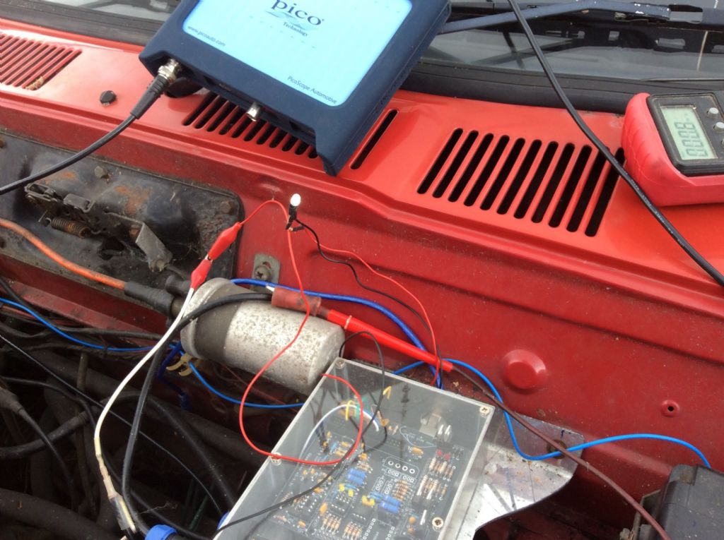
        7 Connected Picoscope to check for spikes

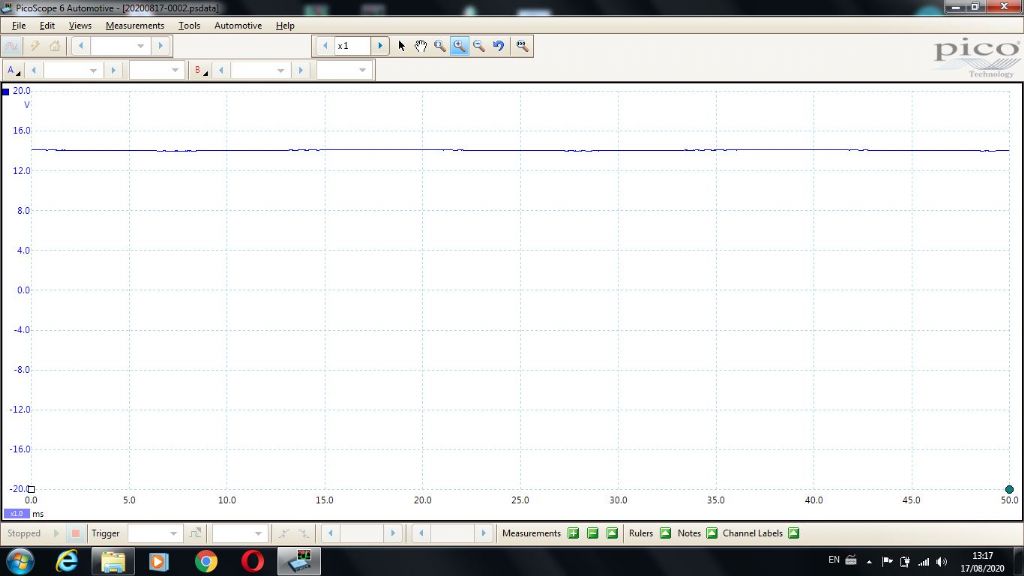
        batteryvoltage.jpg

        The above is battery voltage with engine running.


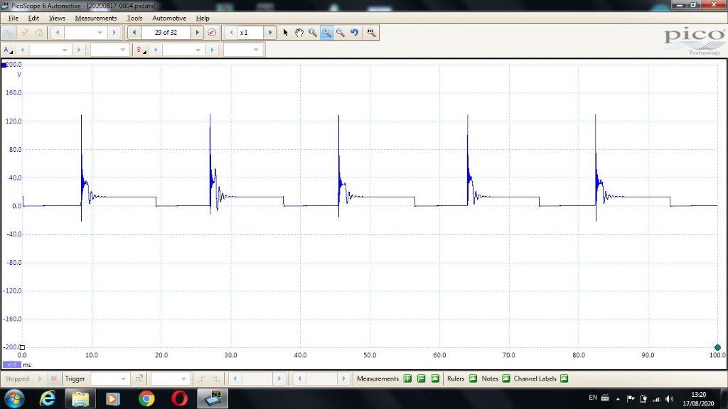
        ledoncoil.jpg

        The above is across the coil connected to Led leads

        coil


        battery


        Hope this helps regarding spikes etc, negative spikes 20v positive approx 130 v

        This is why I think there is a wiring fault in the car

        The spikes do not affect the Led

        Maurice

        Edited By Maurice Taylor on 17/08/2020 14:19:15

        #491113
        SillyOldDuffer
        Moderator
          @sillyoldduffer
          Posted by Bryan Cedar 1 on 17/08/2020 13:00:02:

          "Never before in the history of Model Engineer Forum has such a small item attracted such intrest"

          Apart from coronavirus, which is much smaller – only 125 nanometres in diameter!

          Dave

          #491116
          Tim Stevens
          Participant
            @timstevens64731

            SoD's summary is almost right. The oil pressure gauge is totally non-electrical, so is not related to the failure. And the LED in questions is on the door and shines like a torch onto the oil gauge in the dashboard (there being no easy way to put a lamp into the body of the gauge).

            Has anyone handy to Ludlow got an oscillator they are not using … ?

            Cheers, Tim

            #491120
            Robert Atkinson 2
            Participant
              @robertatkinson2
              Posted by Maurice Taylor on 17/08/2020 14:17:59:


              Hi,

              I have just tested my clear Led with 820 ohm resistor in series on my 40 year old coil and distributer ignition Fiesta.

              1 Connected Led to battery, Led lit.

              2 Started and revved engine ,left running 5 minutes ,still lit.

              3 Turned engine off ,still lit.

              4 Connected Led between points side of coil and ground.

              5 Started engine ,Led lit ,revved as before,left running, still lit.

              6 Stopped engine ,Led not lit, restarted engine ,Led lit

              Hope this helps regarding spikes etc, negative spikes 20v positive approx 130 v

              This is why I think there is a wiring fault in the car

              The spikes do not affect the Led

              Maurice

              Edited By Maurice Taylor on 17/08/2020 14:19:15

              While this is an interesting demonstration of the magnitude of spikes I note your LED had a 820 ohm series resistor. This is a lot higher than the 470 ohm in the OP's. This gives a much more reasonable 11mA current at 12V (assuming 3 V Vf for LED).

              I can't see what wiring fault would cause the LED to fail.
              As I stated earlier the OP's LEDS seem to be running close t absolute maximum curret rating at 12V.

              Robert G8RPI

              P.S whats the box of electronics next to the coil?

              Edited By Robert Atkinson 2 on 17/08/2020 15:23:50

              #491126
              Michael Gilligan
              Participant
                @michaelgilligan61133
                Posted by Bryan Cedar 1 on 17/08/2020 13:00:02:

                "Never before in the history of Model Engineer Forum has such a small item attracted such intrest"

                .

                With 51 posts to your name … have you been lurking for a long while, or do you just read very quickly ?

                angel MichaelG.

                #491130
                SillyOldDuffer
                Moderator
                  @sillyoldduffer

                  Now I'm confused!

                  I put a 1k resistor in series with a cheap 3mm LED, bought new last month. Forward conducting, it lights at about 1.5V and 20 microamps. With 30V on the dropper resistor, the LED takes 30mA without dying. Not too surprising it survived given the 1k dropper, so I'll repeat the experiment with a 220ohm resistor. That should smoke it!

                  What did surprise me was the same LEDs ability to withstand negative voltage. As far as I can tell on my meter's 50 microamp scale no current is drawn at -30V, and the LED still works when the volts are reconnected the right way round.

                  Looks like my electronics books are out of date. The cheap LED I tested is much tougher than expected.

                  Now thinking about how to make a high-voltage variable DC power supply. At this rate it will be cheaper to buy Tim a new car!

                  Dave


                  Edited By SillyOldDuffer on 17/08/2020 16:49:51

                  #491136
                  Tim Stevens
                  Participant
                    @timstevens64731

                    I have now heard back from Mike Hutchins of Dynamo Regulators. He says:

                    There is no way the regulator itself will produce high voltage spikes.

                    Tim

                    #491153
                    Robert Atkinson 2
                    Participant
                      @robertatkinson2
                      Posted by SillyOldDuffer on 17/08/2020 16:48:17:

                      Now I'm confused!

                      I put a 1k resistor in series with a cheap 3mm LED, bought new last month. Forward conducting, it lights at about 1.5V and 20 microamps. With 30V on the dropper resistor, the LED takes 30mA without dying. Not too surprising it survived given the 1k dropper, so I'll repeat the experiment with a 220ohm resistor. That should smoke it!

                      What did surprise me was the same LEDs ability to withstand negative voltage. As far as I can tell on my meter's 50 microamp scale no current is drawn at -30V, and the LED still works when the volts are reconnected the right way round.

                      Looks like my electronics books are out of date. The cheap LED I tested is much tougher than expected.

                      Now thinking about how to make a high-voltage variable DC power supply. At this rate it will be cheaper to buy Tim a new car!

                      Dave

                      Edited By SillyOldDuffer on 17/08/2020 16:49:51

                      Hi Dave,

                      What colour LED? 1.5 V Vf seems low for a white LED. These are gnerally a blue or near UV LED with phosphor on top of the chip.

                      Red ones are a lot more robust.

                      Robert G8RPI.

                      #491154
                      Robert Atkinson 2
                      Participant
                        @robertatkinson2
                        Posted by Tim Stevens on 17/08/2020 17:26:41:

                        I have now heard back from Mike Hutchins of Dynamo Regulators. He says:

                        There is no way the regulator itself will produce high voltage spikes.

                        Tim

                        The regulator may not, itself, produce spikes but the way it controls the dynamo might cuse the dynamo to do so. I'm not saying it does, but it might. They will not have tested the regulator with every make and model of dynamo.
                        Again just assumptions. I wish I was closer, I'd be on the car with test equipment.

                        Robert G8RPI.

                        #491162
                        SillyOldDuffer
                        Moderator
                          @sillyoldduffer
                          Posted by Robert Atkinson 2 on 17/08/2020 20:47:44:

                          Posted by SillyOldDuffer on 17/08/2020 16:48:17:…

                          Hi Dave,

                          What colour LED? 1.5 V Vf seems low for a white LED. These are gnerally a blue or near UV LED with phosphor on top of the chip.

                          Red ones are a lot more robust.

                          Robert G8RPI.

                          It's a red one. I tested it with 220ohm dropper earlier and took the led up to 110mA without popping it. The 220ohm resistor was smoking.

                          I'll try some other colours tomorrow

                          Got irritated measuring current during the test with my Japanese analogue meter because it ranges 0 to 25 which requires me to think. Got my old Avo7 out – much easier to read; big dial scaled 0-100. I'd forgotten how good AVOs are on a bench.

                          Dave

                          #491166
                          Peter G. Shaw
                          Participant
                            @peterg-shaw75338
                            Posted by Tim Stevens on 17/08/2020 17:26:41:

                            I have now heard back from Mike Hutchins of Dynamo Regulators. He says:

                            There is no way the regulator itself will produce high voltage spikes.

                            Tim

                            Possibly slightly off topic, but I'm going to say that my admittedly limited experience of so-called vehicle electrical suppliers leads me to be very suspicious of the above.

                            Back in the early 1970's I had a VW Beetle to which I fitted a Heathkit radio. Said radio then started acting up with noises on the LW band which were tracked down to the fuel gauge. A recommendation was made, by the local VW dealer to go and see some (supposed) car radio experts in an adjacent town. "Oh no, it can't possibly be the fuel gauge: all it is is a make & break switch operating at a rate to produce an average of (I think) 9v for the fuel gauge".

                            Needless to say, a simple one transistor home designed regulator set to give the required output cured the problem.

                            For those who don't understand, that simple make/break switch was producing square waves which produced high frequencies extending up into the 200KHz range where BBC Radio 2 then resided.

                            As you might expect, I have had a very poor opinion of so-called car electricians ever since.

                            Peter G. Shaw

                            #491203
                            Robert Atkinson 2
                            Participant
                              @robertatkinson2

                              SOD,
                              I agree that forward spikes are likely not the issue unless there is something elso going on. I've used LED's in strobe type applications with pulse currents orders of magnitude higher than rated continious current. The forward pulse limt seems to be the bond wire fusing . Need ot watch out for stray inductance though. Reverse voltage is a differen matter. The shorter wavelength LEDs are more susceptible to reverse voltage.

                              Off topic but interesting, I once looked at white LEDs for a fast strobe application (fluorescence decay measurement) . I thought the phosphor on the LEDs would have a long persitance but somewhat surprisingly it didn't. The fall of light output was actually much faster than even a standard xenon flash tube arrangement. Trouble was gaps in the phosphor's emission spectrum, some at critical points. Ended up witha xenon tube with a SCR across it to turn the tube off quickly. SCR triggered by tube firing pulse via a coaxial delay line.

                              Robert G8RPI.

                              #491235
                              Tim Stevens
                              Participant
                                @timstevens64731

                                I have just made a further test: A failed LED complete with its leads – apply rising voltage, nothing. Reverse leads + to -, nothing. Wiggle the wires to check soldering, still nothing. Apply digital ohm meter to outer end of black lead and direct on the back of the LED – zero ohms. Apply meter to red lead and its connection via the resistor at the back of the LED, 470 ohms. So, both leads seem sound, including the added resistor. Chop off both LED leads, and try bare LED on variable voltage. It lights at 2.6V and is bright at 3.5.V continued OK to 6v – brighter still but not much. So, a good LED was connected by good leads and a good resistor, and it worked new but failed soon after.

                                So – any ideas what is going on? Four LEDs have now failed, in identical circumstances.

                                Bot it may be correct to say that it is nothing to do with spikes. Perhaps even nothing to do with the engine running …

                                Oh dear, what a calamity

                                Tim

                                Edited By Tim Stevens on 18/08/2020 12:22:13

                                #491239
                                Howard Lewis
                                Participant
                                  @howardlewis46836

                                  Would an electronic regulator protect the LED? Am not an expert by any stretch of the imagination, but have used 7805 , 7812, and 7815 regulators. Think that they have a current limit of 1 Amp, when on a sutable heatsink.

                                  No doubt Robert can confirm / correct.

                                  Howard

                                  #491240
                                  Jeff Dayman
                                  Participant
                                    @jeffdayman43397

                                    Would you now reconsider my suggestion of visiting the pound shop for a battery powered book lamp to adapt for a gauge lamp, decoupling the issue from the car wiring / dodgy LED's? Just food for thought

                                    #491241
                                    Tim Stevens
                                    Participant
                                      @timstevens64731

                                      Jeff – look back, and that is one of my 'next steps'. But would I ever remember to turn it off as I parked up in my well-lit garage?

                                      Cheers, Tim

                                      #491242
                                      Michael Gilligan
                                      Participant
                                        @michaelgilligan61133
                                        Posted by Tim Stevens on 18/08/2020 12:20:58:

                                        I have just made a further test: A failed LED complete with its leads – apply rising voltage, nothing. Reverse leads + to -, nothing. Wiggle the wires to check soldering, still nothing. Apply digital ohm meter to outer end of black lead and direct on the back of the LED – zero ohms. Apply meter to red lead and its connection via the resistor at the back of the LED, 470 ohms. So, both leads seem sound, including the added resistor. Chop off both LED leads, and try bare LED on variable voltage. It lights at 2.6V and is bright at 3.5.V continued OK to 6v – brighter still but not much. So, a good LED was connected by good leads and a good resistor, and it worked new but failed soon after.

                                        So – any ideas what is going on? Four LEDs have now failed, in identical circumstances.

                                        Bot it may be correct to say that it is nothing to do with spikes. Perhaps even nothing to do with the engine running …

                                        Oh dear, what a calamity

                                        Tim


                                        .

                                        Yes, I do have an idea, Tim

                                        I mentioned it a while back, but no-one responded so I let it lie

                                        Having identified what I thought was probably your 12V device … The ebay description seems very clear that it is rated for 20mA maximum current, and [thereby] 14V maximum voltage with the appended resistor.

                                        In my opinion this is very risky on a Lead-Acid battery with a likely voltage of 14.2

                                        MichaelG.

                                        .

                                        P.S. ___ It’s the current that kills them

                                        Edited By Michael Gilligan on 18/08/2020 12:56:41

                                        #491248
                                        Grindstone Cowboy
                                        Participant
                                          @grindstonecowboy
                                          Posted by Tim Stevens on 18/08/2020 12:20:58:

                                          So, a good LED was connected by good leads and a good resistor, and it worked new but failed soon after.

                                          So – any ideas what is going on?

                                          Working on the Holmes principle of whatever is left, no matter how improbable, etc. there must be some sort of problem with the resistor or the plain bit of wire. Unlikely as it may sound, I think the resistor must be faulty when under the load of the LED – what I mean is that it may show OK with the miniscule current of the test meter, but somehow cannot pass enough current to light the LED.

                                          And we are entirely sure it's just a plain resistor and nothing more sinister?

                                          Just my guess, but possibly worth testing it some other way? If it's not that then it's the plain bit of wire wink

                                          Rob

                                          #491249
                                          SillyOldDuffer
                                          Moderator
                                            @sillyoldduffer
                                            Posted by Tim Stevens on 18/08/2020 12:20:58:

                                            I have just made a further test: A failed LED complete with its leads – apply rising voltage, nothing. Reverse leads + to -, nothing. Wiggle the wires to check soldering, still nothing. Apply digital ohm meter to outer end of black lead and direct on the back of the LED – zero ohms. Apply meter to red lead and its connection via the resistor at the back of the LED, 470 ohms. So, both leads seem sound, including the added resistor. Chop off both LED leads, and try bare LED on variable voltage. It lights at 2.6V and is bright at 3.5.V continued OK to 6v – brighter still but not much. So, a good LED was connected by good leads and a good resistor, and it worked new but failed soon after.

                                            So – any ideas what is going on? Four LEDs have now failed, in identical circumstances.

                                            Bot it may be correct to say that it is nothing to do with spikes. Perhaps even nothing to do with the engine running …

                                            Oh dear, what a calamity

                                            Tim

                                            That's odd. Appears we have leads, resistor and LED that work when first connected, then fail. But, if the lead, resistor and LED are tested independently, they all pass. In particular if I've understood correctly, the LED works when tested in isolation! We've been assuming the LEDs are killed by an electrical spike, and they're not.

                                            Mechanical problem then. Suggestions:

                                            • Poor joint between resistor, LED and leads. Poorly made, maybe badly crimped, & broken by vibration.
                                            • Connecting leads are brittle and fail when the door is opened and closed. Solid wire, or flex? If solid, maybe it's a copper-washed steel core extra unsuitable for being flexed, and only useful in a fixed installation. (Wire breaks inside the insulation)
                                            • Door crushes the cable and damages it.
                                            • Opening and closing the door pulls the cable and breaks one of the joints.

                                            Any chance of a full post-mortem with careful dismantling looking for subtle damage end to end, breakages, heat or whatever I'd be interested to know if volts applied to the cable appear at the LED, and if not how far they get.

                                            Wot a puzzle!

                                            Dave

                                            Edited By SillyOldDuffer on 18/08/2020 13:30:43

                                            #491254
                                            Anonymous
                                              Posted by Tim Stevens on 18/08/2020 12:20:58:

                                              So – any ideas what is going on? Four LEDs have now failed, in identical circumstances.

                                              Bought on Ebay if I recall correctly? Quite possibly factory QC rejects that then get sold on the grey market to unsuspecting consumers.

                                              Andrew

                                              #491260
                                              john fletcher 1
                                              Participant
                                                @johnfletcher1

                                                Years ago when Led first came on the hobby market you could buy a bag of unmarked/untested Led for a pound, same with zenners at Amateur Radio Rally's, sadly an event of the past. You coughed up and took a risk. John

                                                #491270
                                                Robert Atkinson 2
                                                Participant
                                                  @robertatkinson2
                                                  Posted by Tim Stevens on 18/08/2020 12:20:58:

                                                  I have just made a further test: A failed LED complete with its leads – apply rising voltage, nothing. Reverse leads + to -, nothing. Wiggle the wires to check soldering, still nothing. Apply digital ohm meter to outer end of black lead and direct on the back of the LED – zero ohms. Apply meter to red lead and its connection via the resistor at the back of the LED, 470 ohms. So, both leads seem sound, including the added resistor. Chop off both LED leads, and try bare LED on variable voltage. It lights at 2.6V and is bright at 3.5.V continued OK to 6v – brighter still but not much. So, a good LED was connected by good leads and a good resistor, and it worked new but failed soon after.

                                                  So – any ideas what is going on? Four LEDs have now failed, in identical circumstances.

                                                  Bot it may be correct to say that it is nothing to do with spikes. Perhaps even nothing to do with the engine running …

                                                  Oh dear, what a calamity

                                                  Tim

                                                  Edited By Tim Stevens on 18/08/2020 12:22:13

                                                  Hi,
                                                  This indicates that the LED junction has been damaged. Just connecting a LED to 6 V without a resistor is going to damage it. Do you have a milliammeter on a multimeter you can measure the current laken by the LED when directly on the power supply? I'm pretty sure it is more than 20 mA..

                                                  Likely failure mode for this LED is one area of the junction has gone low resistance (short circuit). With the 470 ohm resistor this prevents the voltage at the junction reaching the emission threshold. With direct connection to supply ther is enough current to drive the voltage across the junction above the emission threshold. It won't last long like this hough.

                                                  A useful check would be to measure the voltage drop across the diode (powered off) in both directions with your multimeter in diode test mose if it has one.

                                                  Robert G8RPI.

                                                  Edited By Robert Atkinson 2 on 18/08/2020 15:22:43

                                                  #491284
                                                  Maurice Taylor
                                                  Participant
                                                    @mauricetaylor82093
                                                    Posted by Robert Atkinson 2 on 17/08/2020 15:23:09:

                                                    While this is an interesting demonstration of the magnitude of spikes I note your LED had a 820 ohm series resistor. This is a lot higher than the 470 ohm in the OP's. This gives a much more reasonable 11mA current at 12V (assuming 3 V Vf for LED).

                                                    I can't see what wiring fault would cause the LED to fail.
                                                    As I stated earlier the OP's LEDS seem to be running close t absolute maximum curret rating at 12V.

                                                    Robert G8RPI

                                                    P.S whats the box of electronics next to the coil?

                                                    Edited By Robert Atkinson 2 on 17/08/2020 15:23:50

                                                    Hi Robert

                                                    I have since tried the same clear Led with a 270 ohm resistor in series,works OK.

                                                    The Led I'm using is CPC Part no SC08786.

                                                    I think the experiment has proved spikes are not the problem,as Led is wired across points ,cant be any more spikey.

                                                    Regarding the box of electronics,it is a homebuilt ECU ,using an Arduino mega ,it will run the ignition using a homemade crank trigger wheel,a BMW crank sensor and a VW wasted spark coil.I haven't fitted fuel injection yet.

                                                    I can change from ECU ignition back to distributer ,by changing plug lead an power connection.

                                                    The project is known as Speeduino, plenty of info on internet.

                                                    Maurice


                                                    Edited By Maurice Taylor on 18/08/2020 16:23:35

                                                    #491313
                                                    Maurice Taylor
                                                    Participant
                                                      @mauricetaylor82093

                                                      Hi Tim ,

                                                      Is your car pos or neg earth ?

                                                      Are all the other led lamps ,plug in items made for cars ?

                                                      Maurice

                                                    Viewing 25 posts - 76 through 100 (of 151 total)
                                                    • Please log in to reply to this topic. Registering is free and easy using the links on the menu at the top of this page.

                                                    Advert

                                                    Latest Replies

                                                    Viewing 25 topics - 1 through 25 (of 25 total)
                                                    Viewing 25 topics - 1 through 25 (of 25 total)

                                                    View full reply list.

                                                    Advert

                                                    Newsletter Sign-up