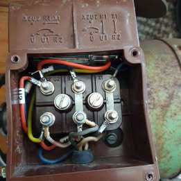
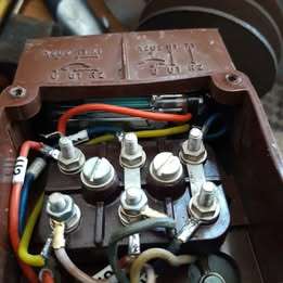
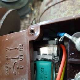
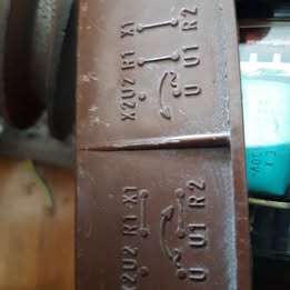
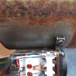
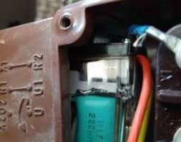
Confusing motor connections – 240v motor
Confusing motor connections – 240v motor
- This topic has 7 replies, 5 voices, and was last updated 24 April 2025 at 12:13 by
 ell81.
- Please log in to reply to this topic. Registering is free and easy using the links on the menu at the top of this page.
Latest Replies
-
- Topic
- Voices
- Last Post
-
-
Hello from Sunny Skegness
Started by:
kevian64
in: Introduce Yourself – New members start here!
- 6
-
24 April 2025 at 16:15
SillyOldDuffer
-
RequiredOutside Diameter to Cut 5/16 BSF Thread
1
2
3
Started by:
James Alford
in: Beginners questions
- 24
-
24 April 2025 at 16:10
Danni Burns
-
Low Current Power Bank
Started by:
Alan Wood 4
in: Electronics in the Workshop
- 1
-
24 April 2025 at 15:57
Alan Wood 4
-
Amolco Mill.
Started by:
Lee Rogers
in: Manual machine tools
- 5
-
24 April 2025 at 15:07
Lee Rogers
-
Parkside Electronics
Started by:
Clive Steer
in: General Questions
- 6
-
24 April 2025 at 14:53
mjbarratt
-
3D printer choices
Started by:
Matt Harrington
in: 3D Printers and 3D Printing
- 11
-
24 April 2025 at 14:01
Michael Gilligan
-
50,000 Ton Press
Started by:
Vic
in: The Tea Room
- 12
-
24 April 2025 at 13:58
halfnut
-
CNC Coolant
Started by:
Steve355
in: CNC machines, Home builds, Conversions, ELS, automation, software, etc tools
- 7
-
24 April 2025 at 13:14
Dave S
-
lifting, levelling and wheeling around a lathe
Started by:
beeza650
in: Beginners questions
- 12
-
24 April 2025 at 12:43
halfnut
-
Confusing motor connections – 240v motor
Started by:
ell81
in: Beginners questions
- 5
-
24 April 2025 at 12:13
ell81
-
Gas Engine Needle Valve
Started by:
Chris V
in: General Questions
- 7
-
24 April 2025 at 09:27
Neil Lickfold
-
original benz
Started by:
tom hardy
in: General Questions
- 2
-
24 April 2025 at 09:12
JasonB
-
First 3D metal Printed Part
Started by:
JasonB
in: 3D Printers and 3D Printing
- 14
-
24 April 2025 at 07:28
Adrian Johnstone
-
VFD Article in May issue 351
1
2
Started by:
Robert Atkinson 2
in: Model Engineer & Workshop
- 12
-
23 April 2025 at 20:49
Robert Atkinson 2
-
Lady Stephanie
Started by:
Steve Huckins
in: General Questions
- 4
-
23 April 2025 at 20:38
alan ord 2
-
Tools scam on Facebook
Started by:
Bazyle
in: General Questions
- 1
-
23 April 2025 at 19:37
Bazyle
-
The Latest INDEX to Model Engineer & Workshop (Also past issues of MEW)
1
2
Started by:
David Frith
in: Model Engineer & Workshop
- 7
-
23 April 2025 at 18:45
Michael Gilligan
-
Motor to lead screw coupling method
1
2
Started by:
nevillet
in: CNC machines, Home builds, Conversions, ELS, automation, software, etc tools
- 17
-
23 April 2025 at 14:33
Michael Gilligan
-
Half Scale 1/4HP A J Weed Engine
Started by:
JasonB
in: Stationary engines
- 4
-
23 April 2025 at 13:52
JasonB
-
Reeves acquires Hemingway Tools?
Started by:
derek hall 1
in: The Tea Room
- 3
-
23 April 2025 at 11:14
Howard Lewis
-
Geography lesson required? Crossley Engine
Started by:
duncan webster 1
in: The Tea Room
- 10
-
23 April 2025 at 11:07
Howard Lewis
-
Hemingway Myford Top Slide Question
Started by:
Nicholas Hill
in: General Questions
- 8
-
23 April 2025 at 10:33
halfnut
-
LMS 2F Experiences
Started by:
Bryan Cedar 1
in: Locomotives
- 6
-
23 April 2025 at 10:28
noel shelley
-
J & S grinder – electrics
Started by:
gerry madden
in: Manual machine tools
- 6
-
23 April 2025 at 10:06
John Hinkley
-
Building Bernard Tekippe’s Precision Regulator
1
2
Started by:
Chris Raynerd 2
in: Clocks and Scientific Instruments
- 10
-
22 April 2025 at 22:20
Chris Raynerd 2
-
Hello from Sunny Skegness


