Confused ….Advice needed rotary table vs dividing head
Confused ….Advice needed rotary table vs dividing head
- This topic has 73 replies, 22 voices, and was last updated 19 February 2021 at 19:44 by
 Michael Gilligan.


- Please log in to reply to this topic. Registering is free and easy using the links on the menu at the top of this page.
Latest Replies
-
- Topic
- Voices
- Last Post
-
-
Help identifying some model engines
Started by:
Mat Dodge
in: General Questions
- 2
-
6 March 2025 at 16:27
JasonB
-
E Bay shot in foot
Started by:
duncan webster 1
in: The Tea Room
- 4
-
6 March 2025 at 16:27
Pete.
-
Vibration and exploring the Fast Fourier Transform with CAD
Started by:
SillyOldDuffer
in: CAD – Technical drawing & design
- 8
-
6 March 2025 at 16:22
SillyOldDuffer
-
Clarkson Tool and Cutter Grinder Operator@s Manual
Started by:
Derek Toller 1
in: Manual machine tools
- 8
-
6 March 2025 at 15:52
noel shelley
-
Telescope Leadscrew Advice
Started by:
Dr_GMJN
in: General Questions
- 2
-
6 March 2025 at 15:35
DC31k
-
Kelsey Media buys Mortons titles
1
2
Started by:
Colin Bishop
in: Website Questions, Comments, and Suggestions
- 15
-
6 March 2025 at 15:14
Colin Bishop
-
Warco WM18B CNC conversion
Started by:
Tomek
in: CNC machines, Home builds, Conversions, ELS, automation, software, etc tools
- 11
-
6 March 2025 at 13:26
Tomek
-
Seen on FaceBook
Started by:
Vic
in: The Tea Room
- 1
-
6 March 2025 at 13:20
Vic
-
Miniature Railway at Olympia (?) around the balcony
Started by:
timdunn
in: Exhibitions, Shows and Club Events
- 4
-
6 March 2025 at 12:00
Nicholas Farr
-
Looking for an OCR package with ‘snap’ facilities
Started by:
Greensands
in: The Tea Room
- 11
-
6 March 2025 at 11:34
peterhod
-
DRO Origin Setting
1
2
Started by:
Peter Cook 6
in: Beginners questions
- 21
-
6 March 2025 at 11:29
peterhod
-
Electric magnet
Started by:
robin coleman
in: Electronics in the Workshop
- 6
-
6 March 2025 at 11:28
Michael Gilligan
-
Resize photos W11
Started by:
duncan webster 1
in: Help and Assistance! (Offered or Wanted)
- 11
-
6 March 2025 at 10:29
Russell Eberhardt
-
What Did You Do Today 2025
1
2
3
Started by:
JasonB
in: The Tea Room
- 19
-
6 March 2025 at 09:58
Roderick Jenkins
-
Slow Again?
1
2
3
Started by:
JasonB
in: Website Questions, Comments, and Suggestions
- 23
-
6 March 2025 at 09:50
SillyOldDuffer
-
Prat Burnerd Griptru adjustment
Started by:
vic newey
in: Workshop Tools and Tooling
- 6
-
5 March 2025 at 21:26
Paul Lousick
-
Midlands Model Engineering Exhibition
Started by:
alan ord 2
in: General Questions
- 7
-
5 March 2025 at 21:10
Lathejack
-
A” WEAVER “1CC DIESEL ENGINE
1
2
Started by:
KEITH BEAUMONT
in: I/C Engines
- 8
-
5 March 2025 at 20:27
KEITH BEAUMONT
-
Homemade Headstock Lathe 1 fondry work
Started by:
celso ari schlichting
in: General Questions
- 4
-
5 March 2025 at 20:18
celso ari schlichting
-
Oil grooves for bushings?
Started by:
keith hodgson
in: Help and Assistance! (Offered or Wanted)
- 10
-
5 March 2025 at 19:11
keith hodgson
-
THE MONTHLY TIPS COMPETITION – THE ENTRY THREAD!
1
2
Started by:
Neil Wyatt
in: Hints And Tips for model engineers
- 13
-
5 March 2025 at 17:03
bernard towers
-
Wood Tool Chests
Started by:
WorkshopPete
in: Workshop Tools and Tooling
- 3
-
5 March 2025 at 15:45
WorkshopPete
-
Rotary table digital readout
Started by:
petetwissell
in: Workshop Tools and Tooling
- 2
-
5 March 2025 at 15:38
Russell Eberhardt
-
Taig lathe DC motor
1
2
Started by:
Peter Cook 6
in: Work In Progress and completed items
- 12
-
5 March 2025 at 12:33
Robert Atkinson 2
-
3/16” BSF mill gib screws
1
2
Started by:
Graham Horne 2
in: General Questions
- 14
-
5 March 2025 at 11:52
Graham Horne 2
-
Help identifying some model engines
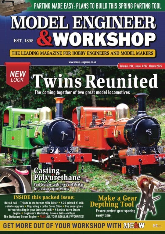
Latest Issue
Newsletter Sign-up
Latest Replies
- Help identifying some model engines
- E Bay shot in foot
- Vibration and exploring the Fast Fourier Transform with CAD
- Clarkson Tool and Cutter Grinder Operator@s Manual
- Telescope Leadscrew Advice
- Kelsey Media buys Mortons titles
- Warco WM18B CNC conversion
- Seen on FaceBook
- Miniature Railway at Olympia (?) around the balcony
- Looking for an OCR package with ‘snap’ facilities

