Con-rod design question

Advert

Con-rod design question

Home Forums Stationary engines Con-rod design question

Viewing 25 posts - 1 through 25 (of 26 total)
  • Author
    Posts
  • #216705
    Tim Stevens
    Participant
      @timstevens64731

      Many stationary steam engines and some mobile ones have a connecting rod which bulges out in the middle. This makes no sense to me.

      If the rod is treated as a column it would be lighter (and so better) if the rod had the same section throughout. But it is in reality a column which is flapping about, so extra mass in the centre is not just too heavy, it also promotes bending. Just what you don't want.

      Were the designers of such machines quite ignorant of ordinary principles?

      Cheers, Tim

      Advert
      #3276
      Tim Stevens
      Participant
        @timstevens64731

        Why thicker in the middle?

        #216716
        JasonB
        Moderator
          @jasonb

          They just had a good eye and liked the asthetics, I do believe the Greeks had a "Bulge" in their columns too.

          #216722
          Michael Gilligan
          Participant
            @michaelgilligan61133
            Posted by JasonB on 17/12/2015 16:13:44:

            … I do believe the Greeks had a "Bulge" in their columns too.

            .

            That's entasis, Jason, and typically very subtle

            A very interesting question, Tim !!

            MichaelG.

            #216723
            Tim Stevens
            Participant
              @timstevens64731

              The Greeks, who had little regard for science, were interested in the appearance of the columns, and they had them tapered, but with an increasing taper as they went upwards. Not a bulge, then, but nearly parallel at the base, more tapered at the top. And intended, so we are told, to look right (which in all credit to the Greeks, they do). Entasis is the name for this sort of tapering.

              And anyway, their columns were stationary. I have no problem with bulges etc on stationary columns, such as those holding the plates of clocks apart, or supporting the headwork of Victorian mill engines etc.

              Regards, Tim

              #216725
              Neil Wyatt
              Moderator
                @neilwyatt

                If you try and bend a rod, where does it bend?

                The greatest stress is at the middle. You can reduce the amount of metal at the ends without weakening it.

                Neil

                #216727
                Geoff G
                Participant
                  @geoffg

                  I'm new to the forum, but happy to reveal how my memory has faded over the 50-odd years since I went to college.

                  In response to Tim's enquiry, I don't think that the old guys were short of knowledge of the basic principles, more lacking the better techniques and materials that we have today. Yes, the bulge in the middle of the long con-rods does add weight just where you don't want it, but it also provides increased resistance to the bending forces created by the acceleration / deceleration caused by swinging one way then the other. Now for the hazy memory bit: I seem to recall that the bending strength increases in proportion to the cube of the depth of the section, so that the improvement in the stiffness of the rod is much greater than the addditional loading imposed by the weight of the bulge.

                  For an extreme example, look at the Sydney Harbour Bridge. It works rather better with that wonderful arch than it would as a flat slab, despite the considerable weight of all that superstructure!

                  And yes, Jason, the bellying of the rods does look much better than a straight con-rod, but, unlike the entasis feature of Greek columns, I think that aesthetics was not the reason uppermost in the minds of the old engineers when arriving at their solution to a problem.

                  Regards to all,

                  Geoff G

                  #216748
                  Michael Gilligan
                  Participant
                    @michaelgilligan61133
                    Posted by Neil Wyatt on 17/12/2015 17:10:47:

                    If you try and bend a rod, where does it bend?

                    The greatest stress is at the middle. You can reduce the amount of metal at the ends without weakening it.

                    .

                    I don't 'have the maths' to offer any calculations, but: Consider a good palette knife [or a rapier, or a fishing rod, etc.] … these are tapered from the 'fixed' end to the tip, so that the bending is nicely distributed along the blade. The fish-bellied connecting rod is rather like a pair of these joined at the hilt.

                    MichaelG.

                    dont know

                    Interestingly: a strand of dry spaghetti [i.e. a brittle, slender rod] will usually break into three pieces when bent.

                    #216754
                    Robert Dodds
                    Participant
                      @robertdodds43397

                      As with Geoff G, my college recollections from 50+ years ago are sometimes hazy but I do remember considering the con rod as a compound pendulum and the effects of transferring some of the mass away from the big end of the con rod to influence the rotational force arising from the radial acceleration of the whole rod.
                      It was thought to be a contributor to piston slap, particularly troublesome in petrol engines.
                      Our early engineering forebears may not have had the technological tools available today like finite element analysis but they did not lack in persistence and thorough testing procedures to try out their new ideas.

                      Bob D

                      #216761
                      JasonB
                      Moderator
                        @jasonb

                        Thanks for teh Link Michael, I did not know it had a name but at least I was correct in saying they had a bulge (convex) shape and not a taper

                        #216764
                        Tim Stevens
                        Participant
                          @timstevens64731

                          I stand by what I said about the shape of Greek columns. A cylinder which gets smaller in diameter from one end to the other is tapered. Any 'bulge' exists at the larger end, and the central part of a Greek column (ie the part where the rods I described do indeed bulge) is in every place smaller than the large end. But let's not fall out about it, eh?

                          Tim

                          #216772
                          steve de24
                          Participant
                            @stevede2433577

                            Here is my explanation. The ends of a con-rod are pin jointed by the big end and crosshead joints. When the con-rod is about to buckle under compressive load it will be bending into a half sine wave. Bending stress is proportional to rate of curvature which is zero at the pin joints (they are hinges and can't transmit bending moment) and max in the middle of the con-rod. So the rod section can be reduced at either end with no loss of strength – but it has to be large enough to carry the compressive load. Steve.

                            #216775
                            Anonymous
                              Posted by Tim Stevens on 17/12/2015 14:52:45:

                              Were the designers of such machines quite ignorant of ordinary principles?

                              Rather harsh methinks……………

                              I agree with 'steve de24', it's most likely all to do with buckling. A connecting rod is fairly slender and when in compression is more likely to fail by buckling rather than exceeding the compressive strength of the material. The connecting rod is also subject to some radial forces, which will promote buckling. I'd say that the centre of the rod is thickened to increase the resistance to bending, and hence buckling, although of course it amounts to the same thing as stated by 'steve de24'.

                              Andrew

                              #216790
                              Neil Wyatt
                              Moderator
                                @neilwyatt

                                Locos also often have fish-bellied rods – now you want them to be as light as possible, especially on an express. The fish-belly is no more decorative than the fluting. Indeed many stationery engine had bellied and fluted rods to maximise strength while reducing weight.

                                Neil

                                > Interestingly: a strand of dry spaghetti [i.e. a brittle, slender rod] will usually break into three pieces when bent.

                                It breaks in one place, but then the whiplash effect causes a second break.

                                #216793
                                Michael Gilligan
                                Participant
                                  @michaelgilligan61133
                                  Posted by Neil Wyatt on 18/12/2015 08:07:46:

                                  > Interestingly: a strand of dry spaghetti [i.e. a brittle, slender rod] will usually break into three pieces when bent.

                                  It breaks in one place, but then the whiplash effect causes a second break.

                                  .

                                  Ah, but … The interestiing part is the location of that first break — hence my mention of palette knives, etc.

                                  MichaelG.

                                  P.S. … Just found this video — Feynman would have been impressed. star

                                  #216796
                                  JA
                                  Participant
                                    @ja

                                    I went to sleep last night thinking about this and, as above, came to the conclusion that the compressive load, from steam/gas pressure and the acceleration/deceleration of the piston, on the conrod was the major factor. The rod, if long, will fail as a strut. If the engine speed is low bellying of the rod is adequate. However when the speed is increased the angular acceleration of the rod around the gudgeon pin will effectively increase the weight of the rod. The rod is also a simple beam with a built in weight (more correct to say that than mass) and will bend due to the angular acceleration. The last thing you want with a strut. To prevent the rod from collapsing as a strut at "high" speeds the second moment of area needs to be increased and the cross sectional area decreased. Therefore designs such as fluting the rod are used instead of bellying.

                                    On real high speed engines, conventional IC engines, the strut problem disappears since the rod is very short but the bending loads increase due to the very high angular accelerations. These rods are very heavily fluted.

                                    I hope this makes sense.

                                    JA

                                    #216799
                                    Michael Gilligan
                                    Participant
                                      @michaelgilligan61133

                                      Introducing an Astronomical note to this discussion devil

                                      It's worth looking at the engineering of Transit Instruments, etc.

                                      **LINK**

                                      Although essentially static; they are built to minimise sag, and the "shaft" is made stiffer in the middle [admittedly, the cones are hollow, so the weight increase is not proportional].

                                      Yes; the loadings are applied differently to those in the con-rod, but the bending effect is comparable.

                                      MichaelG.

                                      .

                                      P.S. … Is there a Finite Element Modeller in the House question

                                      #216803
                                      Neil Wyatt
                                      Moderator
                                        @neilwyatt

                                        So 'whiplash', but in a more subtle sense the whipped rebound of the broken part creating a tighter bend rather than one going the other way.

                                        We can now calculate the speed of sound in spaghetti.

                                        Neil

                                        #216813
                                        Martin Kyte
                                        Participant
                                          @martinkyte99762

                                          My take on this 'in words' is that connecting rods like columns fail by buckling under compression. In this type of failure bucking increases the bending stress on the shaft which in turn causes increased bucking. There is positive feedback in this mode of failure. The ends of the shaft or rod are constrained by the bearings and can be of smaller cross section. The portion in the middle is made stiffer by having a larger cross section. Therefore the weight is minimised and the stiffness is sufficient to resist bucking. I strongly suspect the bending moment is greatest at the centre but I have yet to find the maths for that. If you look at many beam engines the connecting or pump rods are of a X cros section as well as being fish bellied which reduces the weight whilst improving the stiffness.

                                          regards Martin

                                          #216841
                                          Fowlers Fury
                                          Participant
                                            @fowlersfury

                                            Not perhaps a response to the original post, but there's an interesting section in The Engineers' Pocket Book of 1943 covering the design aspects of steam engines. (A fascinating little book despite its age & useful for diagrams of locomotive ancillaries such as lubricators, vacuum pumps etc).

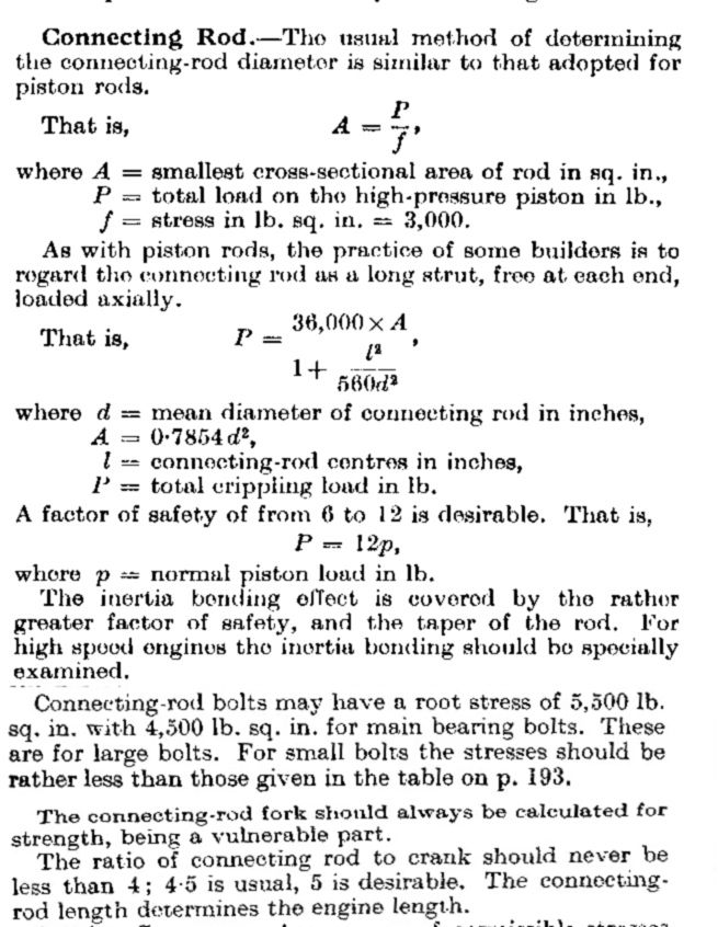
                                            In the part covering connecting rods with its formulae for determining rod diameter, it states "The inertia bending effect is covered by the rather greater factor of safety and the taper of the rod". From which, I suppose, it might be inferred that a fish-bellied rod having two tapers, is stronger ~ as Martin Kyle comments.

                                            con rod_1.jpg

                                            #216845
                                            Gordon W
                                            Participant
                                              @gordonw

                                              Just to liven you up a bit more- If you watch a long con-rod, such as a stationary steam engine or the rod on a knife bar mower, you will see two nodes. These are at 1/3 and 2/3 rds along the length, due to combination of bending and compression loads. I have seen this using a strobe light. This does not happen with short I/C rods.

                                              #216851
                                              Martin Kyte
                                              Participant
                                                @martinkyte99762

                                                That follows the pattern Gordon constrained at both end so nodes. 2 nodes 1/4 along the bar and the middle showing maximum flexure. Failure must occur when the compressive stress from the bend plus the compressive stress from the normal operation exceeds the elastic limit of the bar and it collapses. Therefor put more meat in the middle to stop it flexing as much, keeping the material below the elastic limit. Loco con rods should be treated as long columns and I guess short con rod as short columns.

                                                I read that short columns fail when the bending and direct stress exceeds the yield point of the material and long columns when the elastic limit is exceeded. Short columns are defined as l/r less than 100 (length and radius).

                                                This essentially means that long columns will not tolerate non linear deformation in the cross section as the stress becomes self sustaining and increases rapidly to failure. Short columns do not suffer this.

                                                regards Martin

                                                #216861
                                                Russell Eberhardt
                                                Participant
                                                  @russelleberhardt48058

                                                  Many years ago I rebuilt a 1930 Talbot sports car, identical to those that came first and second in class and on handicap at the 24 Heures Du Mans race in that year. Not quite the same but it had slender fish bellied push rods to reduce the weight while maintaining the required strength. They were originally made by a knitting needle manufacturer.

                                                  Russell.

                                                  #216896
                                                  Mark C
                                                  Participant
                                                    @markc

                                                    Martin comes close to mentioning the important terms, I will mention them implicitly: "Slenderness ratio" and it references the radius of gyration to the length (the l/r mentioned above). If there are any crane designers or (probably) structural engineers they would be able to recognise the question and answer it eloquently but I will decline and leave you all to search the term I suggest!

                                                    Mark

                                                    #216916
                                                    Neil Wyatt
                                                    Moderator
                                                      @neilwyatt

                                                      I was going to say I can't recall coming across a con rod 50 times as long as its diameter – but then I realised the valve rod of a model I am making probably is, the pump rod isn't far off either. I can't think of a piston con rod that is that slender.

                                                      Neil

                                                    Viewing 25 posts - 1 through 25 (of 26 total)
                                                    • Please log in to reply to this topic. Registering is free and easy using the links on the menu at the top of this page.

                                                    Advert

                                                    Latest Replies

                                                    Home Forums Stationary engines Topics

                                                    Viewing 25 topics - 1 through 25 (of 25 total)
                                                    Viewing 25 topics - 1 through 25 (of 25 total)

                                                    View full reply list.

                                                    Advert

                                                    Newsletter Sign-up