CNC Lathe Scratch Build

Advert

CNC Lathe Scratch Build

Home Forums Work In Progress and completed items CNC Lathe Scratch Build

Viewing 23 posts - 151 through 173 (of 173 total)
  • Author
    Posts
  • #564622
    blowlamp
    Participant
      @blowlamp

      Get the GSK980TDc manual here.

      Advert
      #564636
      Joseph Noci 1
      Participant
        @josephnoci1

        Get the GSK980TDc manual here.

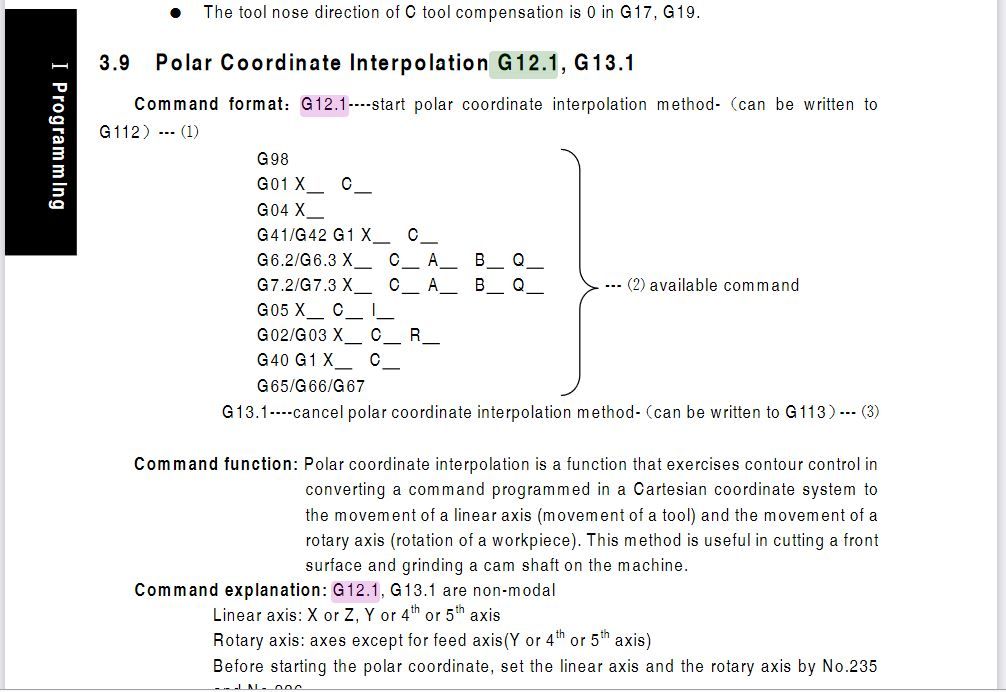
        Nope, No G12.1, G13.1 nor G112 / G113, so can't do!

        And thats the story of my life..

        Joe

        #564639
        blowlamp
        Participant
          @blowlamp

          Are you sure?

          This is from the manual I downloaded.

          gsk280tdc.jpg

          #564689
          Joseph Noci 1
          Participant
            @josephnoci1

            Well….

            I clicked on the link you gave and abt half way down is a table of supported G codes, and G12.1 et-al is missing so looked no further. After what you posted I downloaded the whole manual and it is as you say!

            I need to dig some more – $3K is a lot of money, but if its not good money after bad, may just be my way out!

            Thanks for this info!

            Joe

            #564723
            blowlamp
            Participant
              @blowlamp

              There's a whole range of these CNC lathe controls here.

              I notice UK ebay has a GSK980TDc available for a little over £1000 at the moment, but some of the buttons have Chinese characters – still worth a look, I think.

              Martin.

              #565596
              Joseph Noci 1
              Participant
                @josephnoci1

                Been some progress on the Polar Interpolation. The Polar Interpolation software is working well and tested with a simulator to verify the math. In fact, the math, and the software turns out about 20 lines of code, so very simple.

                The big issue is in the integration with Linuxcnc itself – and this is in line with the usual Linuxcnc pains…

                Switching from 'trivial-kinematics' (essentially cartesian kinematics, with arc's) to 'Polar-kinematics' (with G12.1 g-code – which we had to create and make Linuxnc believe it exists..) is not simple. Since the last axis position before G12.1 was a 'cartesian' one – with a relationship to the machine coordinate zero, and to the work coordinates zero, with tool offsets, when we enter the polar mode, we have to convert that position to a polar one, with the tool remaining in irs current position – so, forward and reverse kinematics, and right now it does not work because linuxcnc is rather convoluted in the way one has access to parameters related to all the machine and work coordinates.

                This project was all about the challenge of the mechanics, never about the software – Boy, was I wrong!

                I decided against the Chinese 'GSKxxx' type controls – scares me a little since when I ( and I will..) find some issue that the controller does not do, improper polar modes, or any thing even very small, there is nothing I can do about it…At least with Linuxcnc I can fool myself into the belief that I can make it work, even if it's now good time after bad!

                Joe

                Edited By Joseph Noci 1 on 05/10/2021 07:23:20

                #566816
                Joseph Noci 1
                Participant
                  @josephnoci1

                  Sloowww progress, but at least it is progress.

                  The Polar interpolation is working well – I have not machined anything so yet, but with a sheet of aluminium centered on a shaft in the chuck and a sheet of paper glued to it, pen in the tool holder, I am drawing very respectable squares,hexes, etc on the paper.

                  issues to contend with now are re-homing the C axis when exiting the polar modes, etc, but those are minor and fairly simple.

                  However, I am frustrated now by what I thought was resolved and simple!

                  I am having a lot of trouble with tool offsets sometimes violating machine limits. This issue is specific to Linuxcnc, so general tool offset management and definition processes for Fanuc, etc, won't help…

                  Is there anyone who has a lathe running Linuxcnc who can chip in and help me understand the tool offsets procedure please…!?

                  #571856
                  Joseph Noci 1
                  Participant
                    @josephnoci1

                    As each hurdle is overcome, another looms large…

                    Polar Kinematics are fully ensconced in The Lathe's Linuxcnc controller and working very well,

                    I believe all the major Linuxcnc issues are at an end, with only a few minor things to still fiddle with.

                    My Good Wife has again proved to be a Star – She decided to work fully with the Linuxcnc source-code since we had some show-stopper issues in machining 'Polar' parts – She eventually found a bug in Linuxcnc, and the Developers agreed and fixed it! So we now have a fully working C axis Live Tool Lathe!

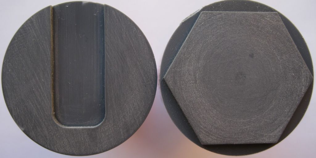
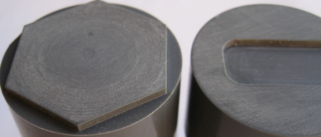
                    Tool offsets are all implemented and working. The fun started when I began to machine test pieces. I did a simple hexagon on the end of a 40mm OD plastic bar, and a U shape across the face of the same sized bar. The U shape is particularly challenging as the milling cutter approached the center of the bar – at that point there are small movements in X with large C axis Rotations.

                    The first result of the machined U …

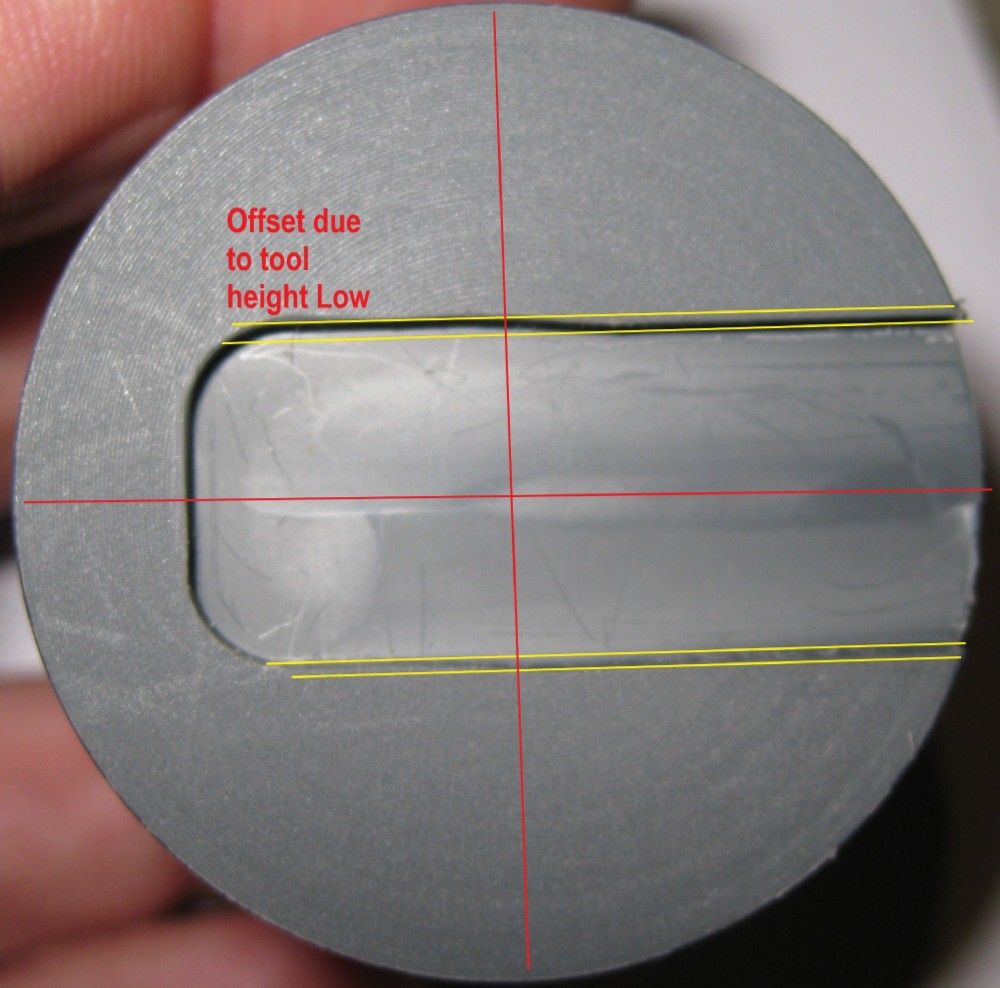
                    Around the centre the cut lines have a 0.2mm deviation – they are parallel, but offset.

                    This was due to tool height, 0.2mm below spindle centerline.


                    tool height offset fault.jpg

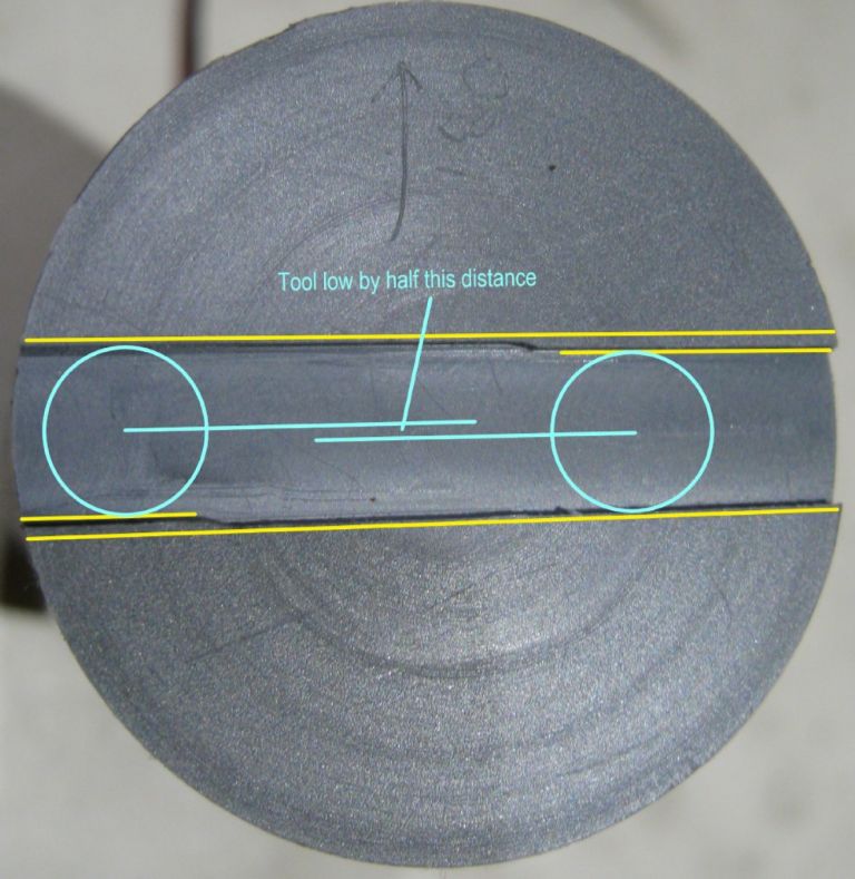
                    This photo shows the 8mm milling cutter cut a slot part way through the bar face, then withdrawn and then the bar rotated 180deg in the C axis and the cutter then brought in again.

                    The cutter cut 0.2mm low each time, hence the offset seen below.

                    tool height error test.jpg

                    The ATC was then raised with 0.18mm brass shim – still a tad low – and another U machined.

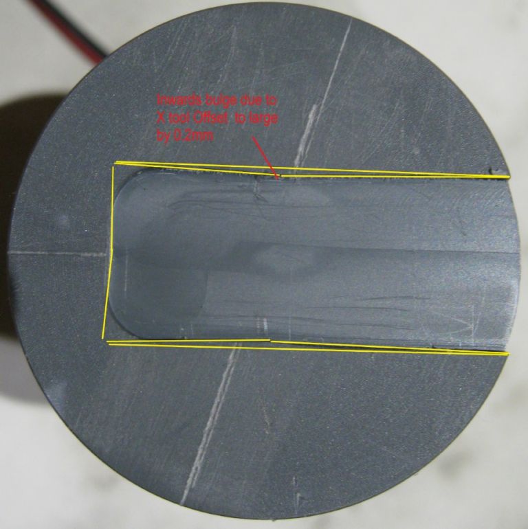
                    This shape made sense and showed that the Live Tool X offset ( G54) was in excess by 0.3mm / 2 ( since the Gcode for these modes are always in 'Diameter Mode'. This clearly shows that the left and right ends of the U are almost at the correct heights, since that is related to tool height and not to X position, while near the center, at the bulge, the C axis is almost at 90 deg, ie, the U sides are vertical, and so X offset plays a big role.

                    This error in X offset ( since all tools are referenced to the master tool in station 1) is due to an error in tool-1 X offset because of poor Homing repeatability and accuracy. I use Hall effect sensors, and extensive tests show no better than 0.2mm spread in detection. So the sensors have to be hugely improved.


                    offset_angle_errors.jpg

                    Sorry about the crappy red text – it says the bulge is due to the X tool offset error of 0.2mm

                    x tool offset bulge error.jpg

                    I then machined the U again, but this time setting the Live tool offset AFTER Homing, ie, eliminating the Home deviation – this could be done each time the machine is switched on, then home would not matter, but that is a pain…Good Home sensors are imperative.

                    The left side of the U shape below is about perfect. The right side not so much… Further investigation reveals that it is actually the bottom right of that edge that bulges out – and that is due to not-so-good resolution on my C axis encoder – 4096edges which gives 0.08deg, with a servo deadband of 3 edges which is 0.24deg accuracy at best, with an additional 0.08deg on top of that for position repeatability. So, I need a much better encoder – 8000 edges or so..2000 pulses. The Hex is off course much better, and much easier to achieve good results – the C axis encoder contributes less error since the x deviation versus C angle change is never as disproportionate as when the cutter is near bar centre. The hex is actually very good within 0.02mm in dimensions which in plastic is not bad.

                    u_hex1.jpg

                    u_hex_oblique.jpg

                    In polar/Live tool mode, every little error has to be fixed, any play, offset, etc is critical, and tool height is King…

                    Will try do a video of the lathe cutting stuff in Polar with the live tool.

                    Joe


                    EDIT _ get rid of grinning smiley's…


                    Edited By Joseph Noci 1 on 18/11/2021 17:17:26

                    #575311
                    Joseph Noci 1
                    Participant
                      @josephnoci1

                      Still No video of the lathe doing some Live Tool Stuff…

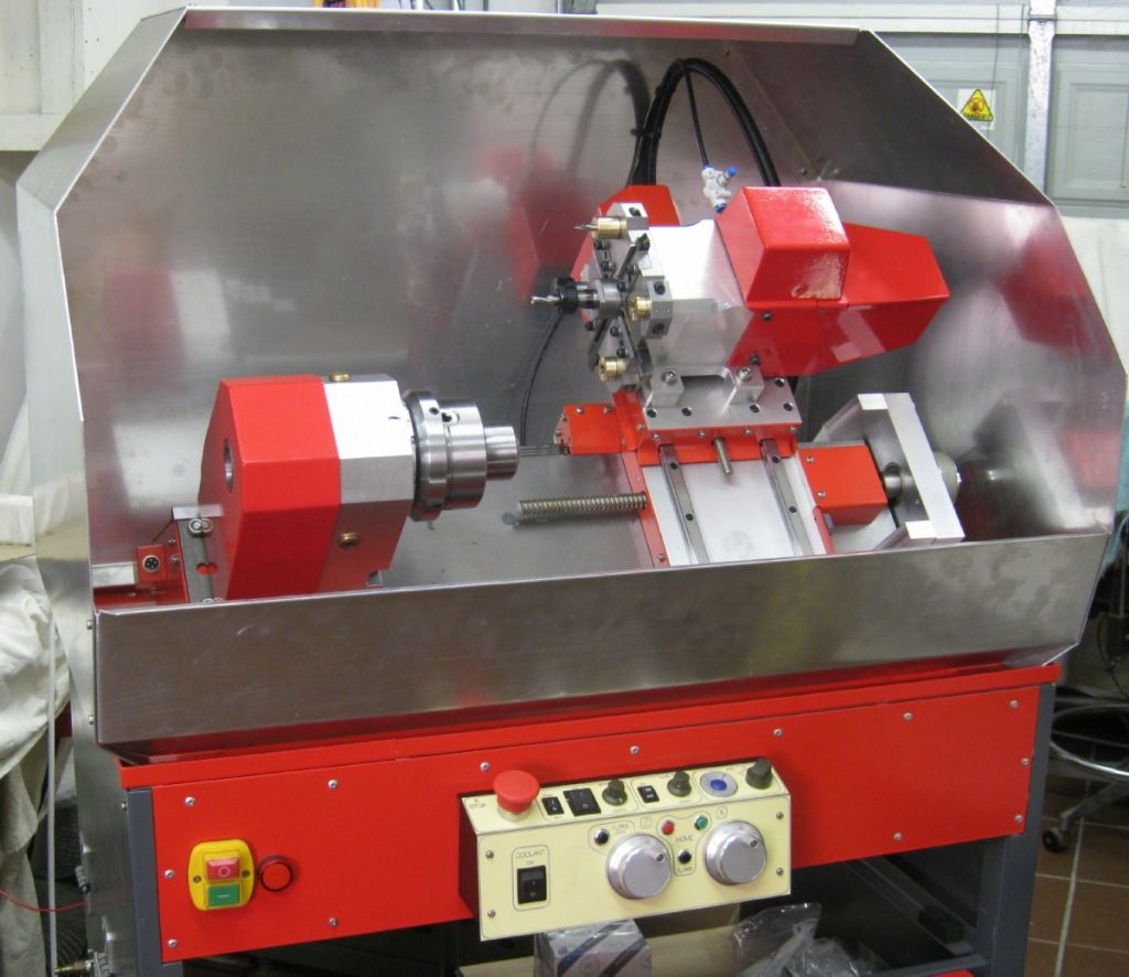
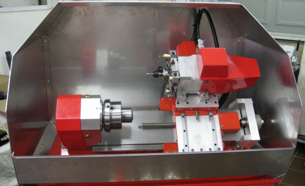
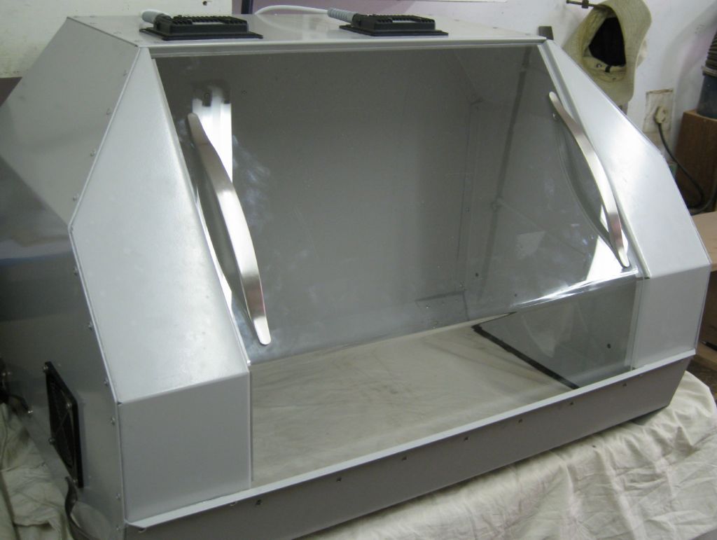
                      I had more than enough of LinuxCNC , and all things Linux, for a while….So am tackling some of the many bits still to be done on the lathe – Coolant pump and piping, Swarf/Splash guards, etc. Coolant is a bit of an issue on a CNC lathe like mine – The tool changer does not incorporate coolant feed pipes for each tool, like the big CNC machines do. I will have one spout, and that means the coolant is sometimes aimed at the wrong place. The spout can be set up reasonable well for most facing/turning/threading tool tips – they are more or less in the same place when selected, give or take 10mm or so. However, a drill bit, boring bar and the live tool center are not so simple. So the Spout has to be 'fixed', ie, does not travel with the carriage, but aims at the workpiece and must really flood it. I also intend to use a positive displacement coolant pump to have good pressure to blast swarf away…

                      Coolant will be neat cutting oil – Castrol Ilocut™ 510 MP,  a chorine and heavy-metal free, multi-purpose neat cutting oil. It can also be used as a hydraulic oil confirming to ISO 6743/4 Type HM, so I wonder if using a thin hydraulic oil is also possible?

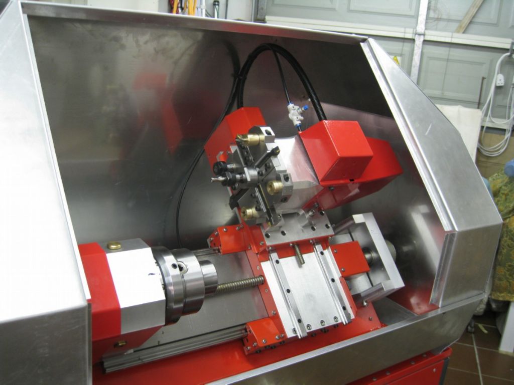
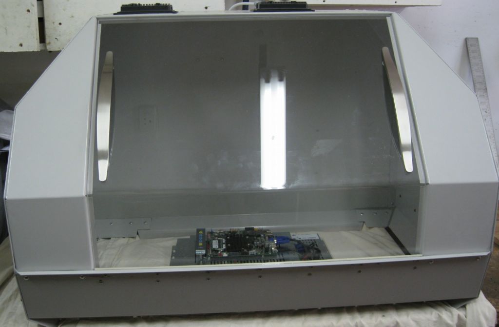
                      So while the design concepts for all that brew, I continued with the Splash guards. This encloses the lathe entirely, to be fitted with a perspex front panel for viewing. I cannot get the flexible acrylic matl in Southern Africa, so Perspex it is..

                      Also have to think a bit about lighting internally – IP66 lights don't exist here…

                      The Guards so far-

                      splash guard1.jpg

                      splash guard2.jpg

                      splash guard3.jpg

                      splash guard4.jpg

                      Edited By Joseph Noci 1 on 13/12/2021 20:56:05

                      #575320
                      Baz
                      Participant
                        @baz89810

                        Looking very impressive.

                        #575323
                        John Haine
                        Participant
                          @johnhaine32865

                          Hi Joseph, on the polar kinematics issue, I don't know if you saw MG's post on a "polar drawing machine" a week or so back, but when I saw it I immediately saw the point you were making! As a result I've been idly wondering about using the technique to do laser engraving of a clock dial – it would make for a simpler machine than having 2 linear axes perhaps.

                          Somewhat related, I see that there is a CamBam plugin to do C-axis mapping of X or Y axes, which I think is mainly of use for doing cylindrical engraving, but as far as I know it can't map X and Y into polar coordinates.

                          Will your joint changes to LinuxCNC make it into the main thread or just be a fork? Sounds like it could be a good feature.

                          The lathe is looking good! Did you make any progress with the tool touch-off system? I was just thinking today about how I could integrate my electromagnetic approach more into the lathe structure. At the moment I have to loop the sensor over the workpiece and make connections to the chuck and toolpost for the excitation current, but this is often difficult with small components. I'm wondering how I could build the sensor into the toolpost structure itself.

                          #575433
                          Joseph Noci 1
                          Participant
                            @josephnoci1

                            Thanks Baz – I am enjoying the building, but it does become a bit much sometimes…

                            John,

                            I suspect my 'code' won't make it anywhere – its is not really universal – the C axis is very specific- using a powerful step/direction servo motor ( not stepper, and not true servo- it is closed loop servo, but closed internal to the motor, with its own servo driver, encoder, etc). The ATC is also unique/specific and so the polar interpolation mode integration is likewise somewhat specific – the math not so, but the glue is rather.

                            The C axis, ATC and a few other bits are Hal compile components, and will never be considered mainstream Linuxcnc code to be integrated into master. Also, a large proportion of the tricks is also all in the INI and HAL files…

                            So, probably not – just another one of those 'brilliant' glitches in life…

                            I admit to not having made progress with a probe setup.. I have only just got to grips with Lcnc's rather cryptic description of how to set up tool offsets…And as the ATC can host 8 tools, I use one master tool (facing roughing tool) , set its offsets accurately once ( painfully) and then set the othesr in reference to the master, also painfully.

                            I need to get the machine done so I can use it and discover how much of a pain it is with future tool setup..A threading, parting, facing/roughing/finishing and triangle tip should cover most simple work without changing tools – the others are drill bits, two fixed boring bars, center drill and live tool.

                            The Polar mode for your laser engraver is good – just be aware of the Atan issue near center – results in rapid rotations of the rotary axis, sometimes 'instantaneous'…Clock face periphery engraving is no problem!

                            There are many polar 3D printers, cheap too, that work like that – a rotary table/disc with a linear arm plus Y axis. Maybe get one of the better ones of that type and hack it?

                            Joe

                            #580362
                            Joseph Noci 1
                            Participant
                              @josephnoci1

                              Progress on the lathe enclosure was somewhat hindered by the holidays – Powder coaters , Perspex suppliers, FESTO piping/stopcock suppliers, LocLine suppliers, etc, all insisted on closing for the holidays…

                              Some have opened, some have supplied and so some progress has been made. Getting close now…

                              The Splash.Swarf enclosure is complete. All the Metalwork is done, painted and together. I used 6mm perpsex for the window ( no sanely priced 'flexicrylic – the non-shatter stuff – available in Southern Africa – R4700.00 for 2.4Mx1.2M, the smallest available)

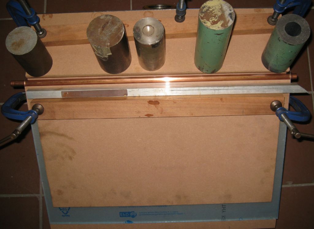
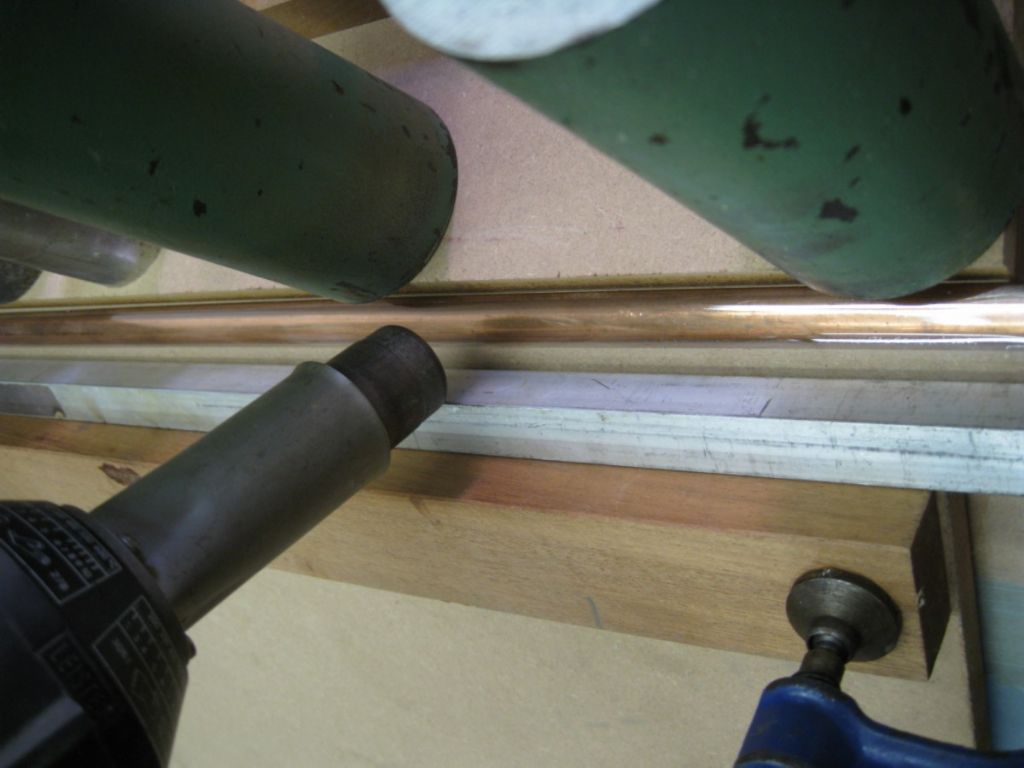
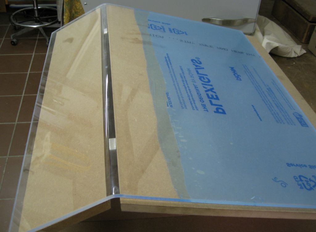
                              This required a 38degree bend in it, so I mad a supawood jig and heat-bent the perspex with a heat gun. That worked very well.

                              bending jig.jpg

                              Heat gun heater..

                              heat gun application.jpg

                              The bent sheet.

                              perspex bent.jpg

                              Handles fitted and cover located on Enclosure window.

                              splash gaurd complete1.jpg

                              splash gaurd complete2.jpg

                              I have to split my post into 2 or 3 it says – 1450 words to many – WHAT??? Don't mind this forums software to much, but this gets me every time and it irks me – there are not even 1400 words in the total post…

                              #580363
                              Joseph Noci 1
                              Participant
                                @josephnoci1

                                Next post with simulated brevity…

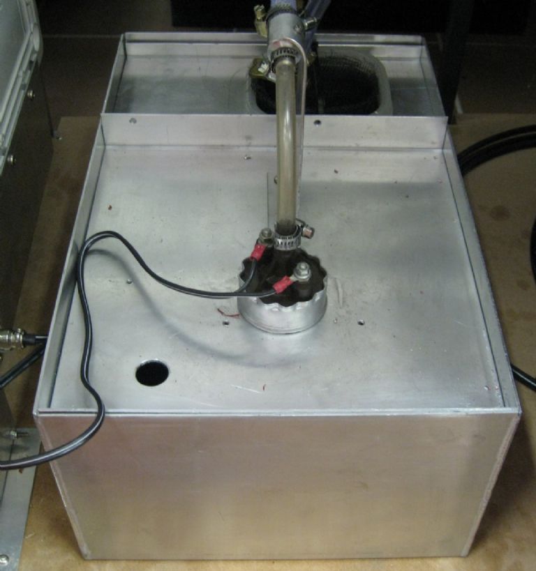
                                The coolant pump is also done and tested.
                                coolant pump.jpg

                                In a previous post I indicated I would use a neat oil 'coolant'/lubricant – That was not a success. The oil was great, very thin, and does is intended job well, but the mess is intolerable. An oil film sits on everything, and just sits there. It does not run off like the water soluble oil solutions do. It sits on the swarf and takes days to drain of, and even then , not so well. So I dug for a more modern soluble and found some excellent stuff – Ecocool 600-NBF, made by Fuchs. from 4:1 to 20:1 mix, and £45.00 for 20liters. When mixed, the solution is clear and has no detectable smell. Drains off quickly, and left pooled on a shiny machined clean mild steel plate over the Christmas/New year week, left not a mark.

                                The pumps is a 12V fuel injection pump – seems to be able to develop a good few bar pressure. It hangs in the coolant tank with an inlet sieve. The drain from the lathe goes through 2 further sieves on route before the coolant drops into the tank. We will see what the coolant mix does to the pumps gears/seals, etc. The pumps was inexpensive anyway!

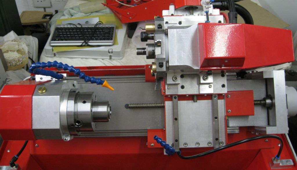
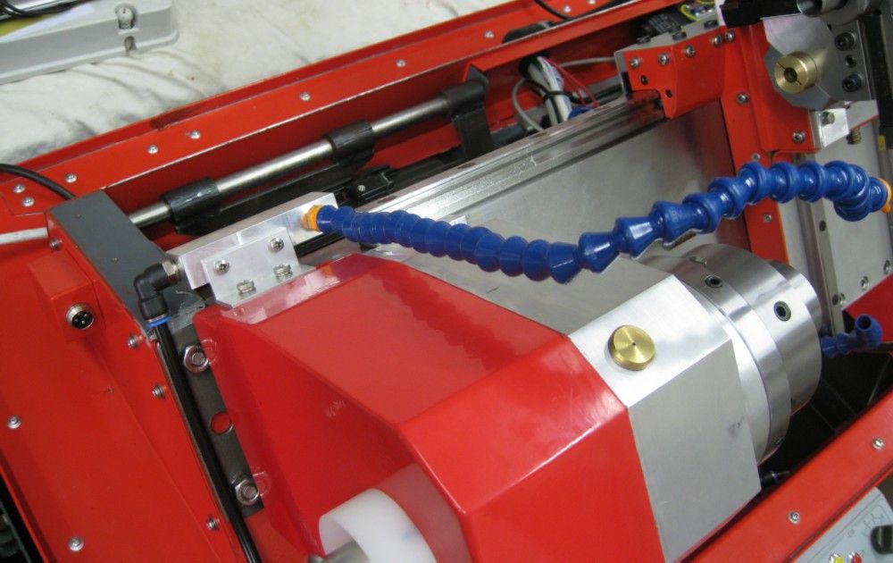
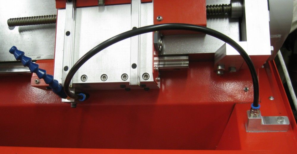
                                Coolant spouts placement on a CNC lathe is a big deal..Normally on the CNC machines the coolant spouts from the tool holder onto the cutting edge, often out the cutter itself with special coolant channels in the cutters, drills, and tool changer. Since that is not possible on my setup, I opted for two spouts, one placed for surface and face cutting, and one for drilling and boring and with Live Tool spindle- the latter spout to the right of the workpiece, the former on the left.

                                (some suppliers are STILL on holiday, so the right spout locline has not yet been lengthened..)

                                The left spout is fixed, and will flood fully the workpiece from behind / under. The right spout moves with the carriage and is aimed at the workpiece center face.

                                left and right coolant spouts.jpg

                                left coolant spout routing.jpg

                                right coolant spout routing.jpg

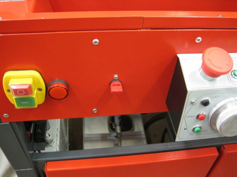
                                left coolant stopcock.jpg

                                Still some machine covers at powder coaters, and when that's done the machine is 'ready' to use…

                                On the software side, My good Wife has modified much about Linuxcnc's basic setup to make a really nice user interface, and with features that make the machine user friendly. I looked at the many 'available' screen MMI options out there for Linuxcnc – some very fancy looking ones, and after detailed investigation decided they are of little use. They tend to be flashy, many buttons and LEDs and options, dozens and dozens..There are 'nice' tools to allow the screens to be easily modified and changed, but likewise, I found that it took days to understand what the creator of that screen had done, what the buttons did, how they tied into Linuxcnc, etc, After writing up a spec of what I wanted on a display, info, buttons, etc, it was clear that these screens were a waste of time they were so much eye-candy, done because the creator could…I bet none of those creators actually ever used one of there creations in a working machine environment!

                                In addition, there are wonderful incompatibilities between the screens ( the language they are written in, Python2) and Linuxcnc Vers2.9, which ONLY works with Python3 addons, etc. Lcnc vers 2.8 is the current 'formal' release, but does not have any of the kinematics and features I need for the C axis / live tool on my lathe.

                                So, My good wife modified the vanilla Linuxcnc AXIS screen definition, down at Python3 level, and we have a very nice screen setup… As soon as the powder coated stuff is back, lathe assembled, etc, videos will happen!

                                On the CAM side, I found a package called KIPWARE :

                                Kipware CAM sofware

                                Which is a conversational CAM tool, works very well, can do my Live tool / C axis with little effort, and allows easy Gcode generation for all basic lathe machining operations. The Company is 'glitzy' and sort of sticks in my throat, the product presentation is also a little garish, but it works and the price is not bad..

                                That's it for now.

                                #580375
                                Joseph Noci 1
                                Participant
                                  @josephnoci1

                                  The KIPWARE mentioned was supposed to be a link to the site – I am sure I set it as a link – maybe mods killed it for me, or maybe I was just dreaming when I did it – here it is again….

                                  Kipware conversational lathe CAM

                                  If it turns un-linky again, then I blame the mods…

                                  #580730
                                  Stefan Hertweck
                                  Participant
                                    @stefanhertweck20280

                                    Hello Noci,

                                    I read this post with high interest. Very impressive work! That also applies to your other previous projects. Also interesting to see what kind of (wildlife) work you do in Namibia. My respect. Greetings from Germany, Stefan.

                                    #580765
                                    Pete.
                                    Participant
                                      @pete-2

                                      As usual Joe, your post is hugely impressive, also as usual the electronics is over my head but from my perspective very impressive, lovely sheet metal work on the enclosure it all looks very factory fit, I'm pleased to see you got very nice results with your ad hoc perspex bending methods, I have on the odd occasion looked at perspex heating units but could never justify it for very occasional use, I remember using one in design class at school and have thought on the odd occasion it would be a nice material to make things with, your results have inspired me to have a go with something similar.

                                      I also agree with Stefan on the wildlife, there's nothing quite like African wildlife, I remember in the early 90's as a 9 or 10 year old climbing out of the swimming pool at a friends house in Harare and there 12 feet in front of me was a 7 foot Cobra reared up with it's neck flared out staring me straight in the eye, one of the other kids shouted "snake" all of the adults suddenly got very serious, my father having served in the Rhodesian armed forces in the late 70's had taken a course Snake Specialty, I believe everyone had to pick an aspect of bushcraft to specialise in, before I knew it he'd grabbed a broom and garden spade pinned it's head down with the broom and swiftly removed its head with the spade.

                                      The gardener was holding the decapitated Snake up on the front garden while my father took a photo, a rotund African lady walked by with two full bags of shopping weighing her down, she looked over saw the gardener (forgive me for forgetting his name I was quite young) holding this huge Cobra and started running down the street screaming, it's one of those images that will be etched into my memory forever.

                                      #591279
                                      Joseph Noci 1
                                      Participant
                                        @josephnoci1

                                        Not really a continuation of the Lathe itself, but related since I am pursuing touch probing concepts for the Lathe.

                                        Most 3D touch probes work on the principal of a lever (the ball attached to the end) moving a tri rod contact from 6 balls, all items electrically in series, so when one rod breaks contact with a ball, the touch probe has made contact.

                                        Some DIY attempts have used a Piezo sounder disc attached to the touch probe, and relies on high gain amplifier detecting the voltage spike from the Piezo when the probe 'strikes' the workpiece. These have various measures of success – contact must be 'definite' – slow approaches require very high gain in the amplifier which then requires deep filtering to prevent machine vibration detection etc…

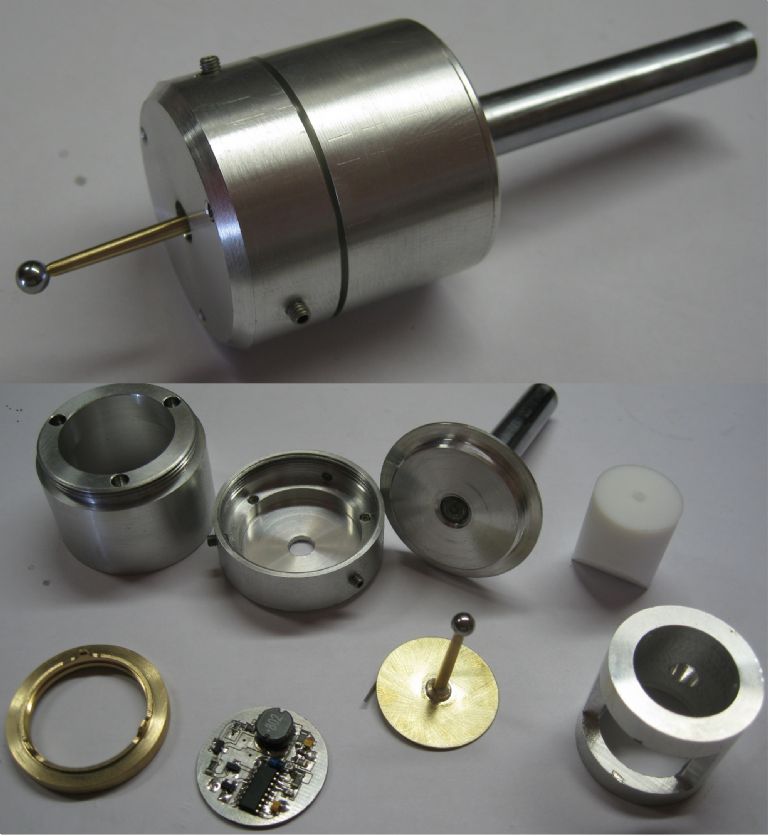
                                        I went another route – used a piezo disc, but in a closed loop oscillator so the probe ball tip 'vibrates' ultrasonically. The disc holder is critical – the piezo disc domes in and out during oscillation, so supporting the disc is normally at 2/3 its diameter. I supported it on the periphery at 3 small points, zero deg, 120deg, and very critical, 220 deg, NOT 240deg. 240deg gave a probe tip up/down motion only, almost no side motion. Moving the 3rd support caused the tip to oscillate up/down and circularly, ie, the tip oscillates all over inside a sphere around 0.003mm larger than the ball on the tip…This was measured with a Laser inteferometer at the local Mining Mineral analysis labs..!!

                                        The piezo disc is a common buzzer disc, with 3 contacts – GND, main contact and feedback contact. The oscillator runs from 1.2V and the feedback is set so that is just oscillates reliably between 0deg C and 50degC. The slightest contact with the ball in ANY plain stops the oscillation. This cessation is detected within 3 oscillation cycles ( @3.9KHz = 0.7msec) . Deflection of the ball at cessation after 200 to-and-fro runs is around 0.008mm in horizontal, and 0.006mm in Z.

                                        It works a darn treat!

                                        The assembled probe and its bits below.

                                        total views.jpg

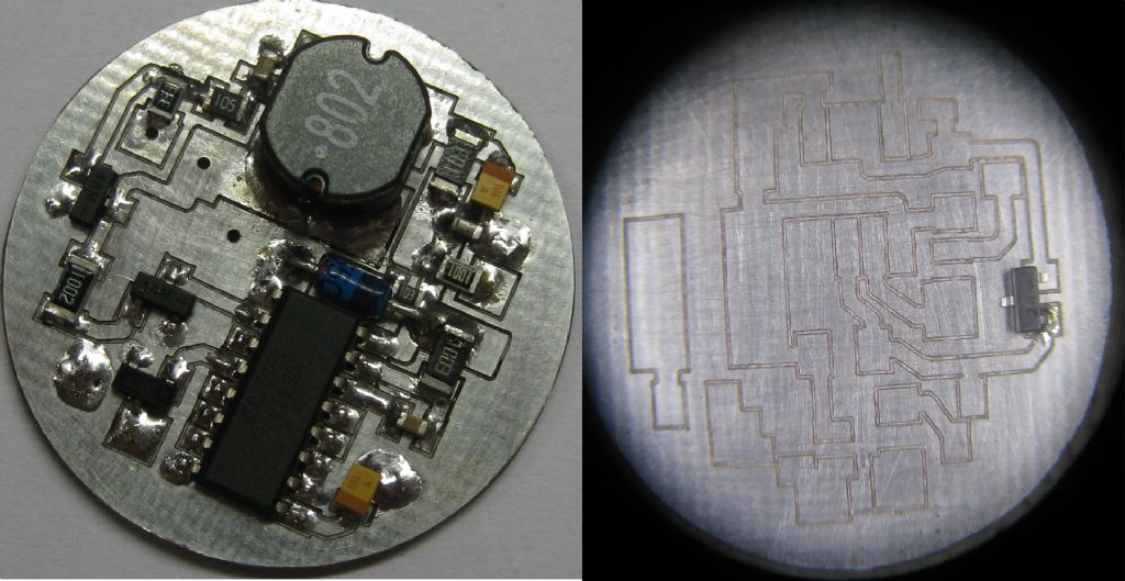
                                        The PCB – engraved on my PCB router..

                                        pcb .jpg

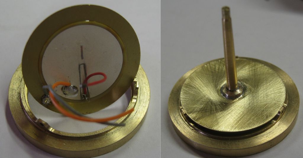
                                        The Piezo disc from the rear – with the disc holder beneath it – left.

                                        The disc with probe, fitted to the holder supported by the three points.

                                        piezo disc and holder.jpg

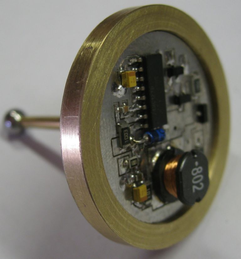
                                        Electronics on the rear of the disc holder

                                        pcb in disc holder.jpg

                                        The jig used to located the probe on the disc when soldering it in place.

                                        probe to disc jig.jpg

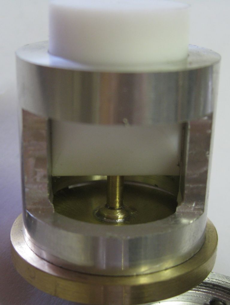
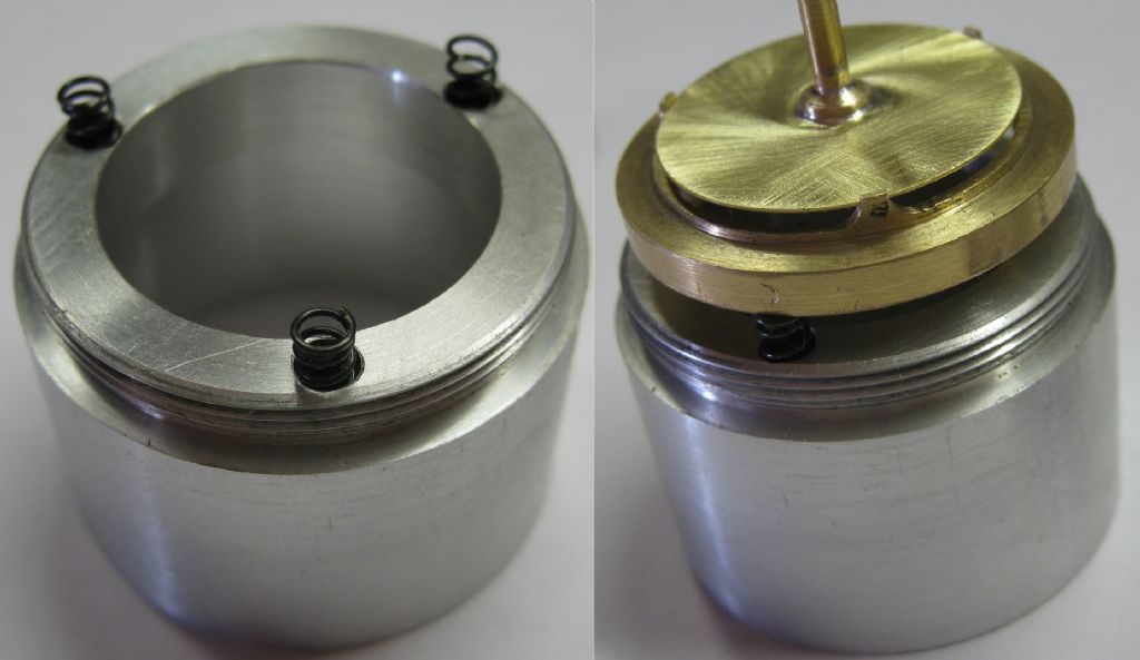
                                        Left, main body with Z springs

                                        Right, disc and holder atop the Z springs

                                        disc holder and z springs.jpg

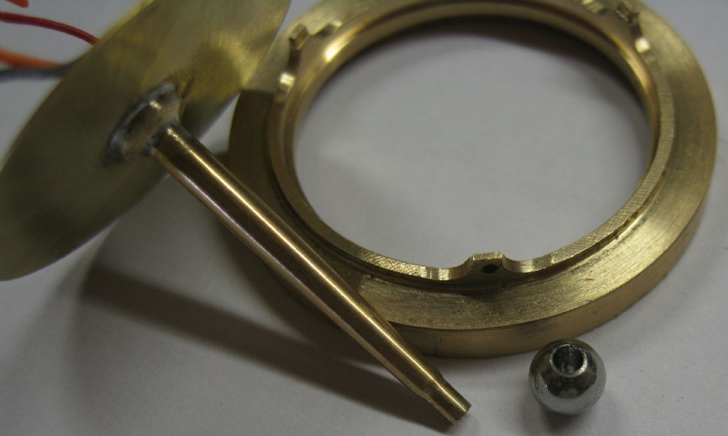
                                        View of the probe tip and drilled ball – also the disc holder

                                        ball and disc holder.jpg

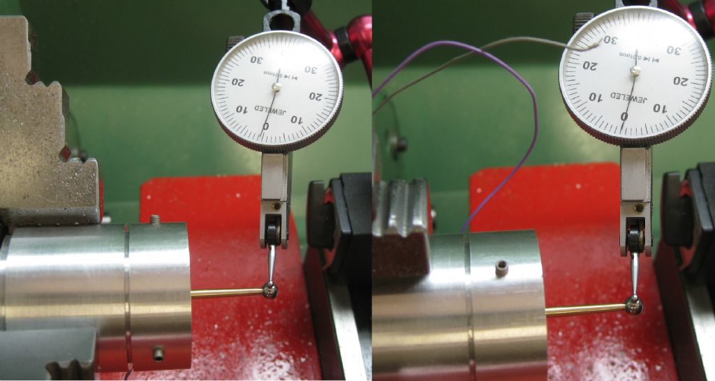
                                        Setting tip runout – 1/2 div @ 0.01mm div guage.

                                        setting runout.jpg


                                        This one for the Mill, another for the lathe – a different shape to fit an arm on the ATC…

                                        Joe


                                        Edited By Joseph Noci 1 on 23/03/2022 17:10:52

                                        #591284
                                        Jeff Dayman
                                        Participant
                                          @jeffdayman43397

                                          Great work on those probes Joseph! well done. Years ago I worked for a smoke alarm firm and had a lot to do with piezo disks for making noise. Never thought to use them for a probe. In smoke alarms we supported the disk with a circular knife edged ring top and bottom , the knife edge was at the nodal diameter of the disk to allow max movement / max noise. The disk was captive in a circular housing which located the disk od at 3 minimal contact points and with about 0.4 mm total clearance on the od. Made millions of alarms with these per year, about 99 % worked perfectly! I recall the disks we used were from Kyocera.

                                          #591285
                                          John Haine
                                          Participant
                                            @johnhaine32865

                                            Joe, that's very neat!

                                            #591286
                                            John Haine
                                            Participant
                                              @johnhaine32865

                                              Joe, that's very neat!

                                              #591454
                                              Joseph Noci 1
                                              Participant
                                                @josephnoci1

                                                Thanks John and Jeff.

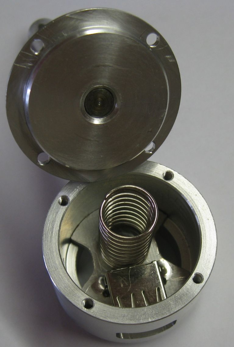
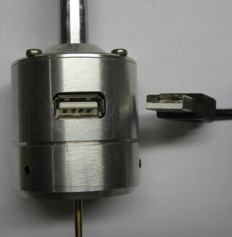
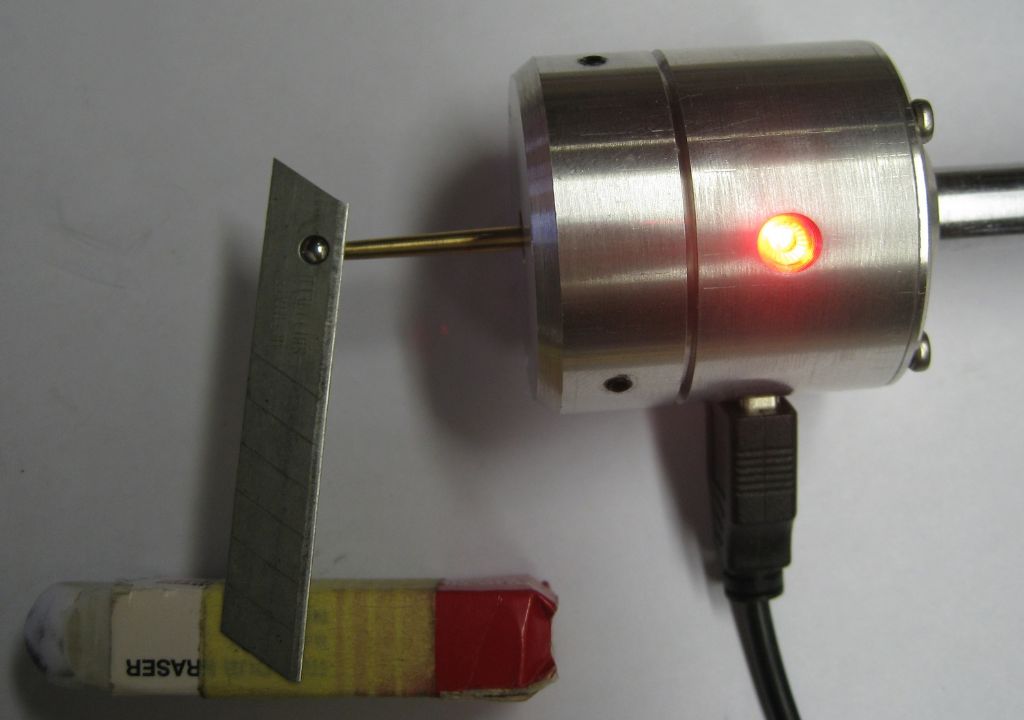
                                                Finished off the probe as far as I want this prototype to go – It really works well. Fitted an LED so I have a visual indication if I use it on a manual mill. Connectors for these items are always an issue – I hacked in a USB-2 connector – use two pins for power and one for the open drain to ground output to Linuxcnc for probe contact. When I do the actual one for the lathe it will be permanently mounted on the cross slide and a different format. The proto in the images is great for the mills.

                                                It is REALLY sensitive less than 1gram activates it fully, and oblivious to machine vibration, etc. A crash ( it happened..) of 4mm overrun pops the Piezo disc out of the tri-point holder with no damage – refit it and recal ( runout) and all works fine again! Of course this is only valid in XY – Z would kill the piezo disc!

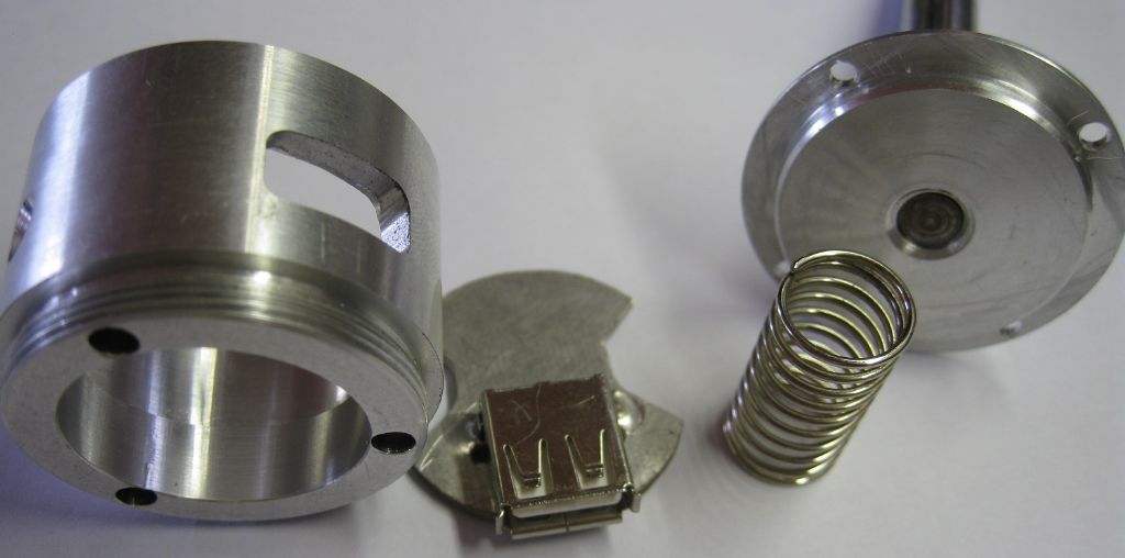
                                                The USB connector pcb – held in place against a rebate by the spring seen below, when the rear shaft and cap is fitted.

                                                usb connector.jpg


                                                spring retainer.jpg

                                                Business end of the USB connector

                                                connector fitted.jpg

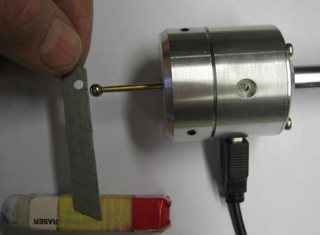
                                                A section of snap-off blade shows how sensitive the unit is. The blade weighs 1.37grams and one end sits on the eraser so the weight on the ball is maybe 0.7grams or so.

                                                no contact.jpg


                                                contact.jpg


                                                And while its powered it sits and sings quietly at 3.9Khz…

                                                Edited By Joseph Noci 1 on 24/03/2022 16:52:42

                                                #611247
                                                sam sokolik
                                                Participant
                                                  @samsokolik60334

                                                  Wow – great work! I totally missed this thread.

                                                Viewing 23 posts - 151 through 173 (of 173 total)
                                                • Please log in to reply to this topic. Registering is free and easy using the links on the menu at the top of this page.

                                                Advert

                                                Latest Replies

                                                Viewing 25 topics - 1 through 25 (of 25 total)
                                                Viewing 25 topics - 1 through 25 (of 25 total)

                                                View full reply list.

                                                Advert

                                                Newsletter Sign-up