CNC Lathe Scratch Build

Advert

CNC Lathe Scratch Build

Home Forums Work In Progress and completed items CNC Lathe Scratch Build

Viewing 25 posts - 126 through 150 (of 173 total)
  • Author
    Posts
  • #560735
    Joseph Noci 1
    Participant
      @josephnoci1

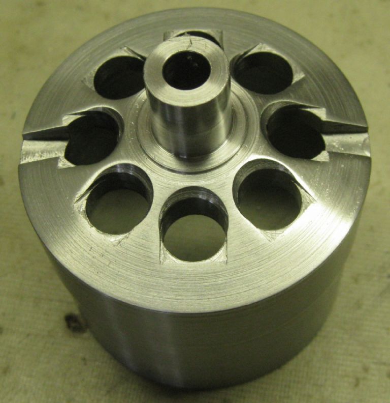
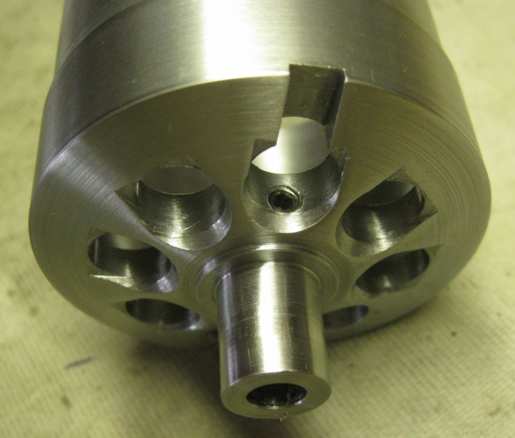
      CNC'ed the air cooling holes into the magnet Rotor housing this morning, and fitted the locking grubscrews. rotor aircooling1.jpg

      rotor aircooling2.jpg

      Getting there…

      Advert
      #561220
      Joseph Noci 1
      Participant
        @josephnoci1

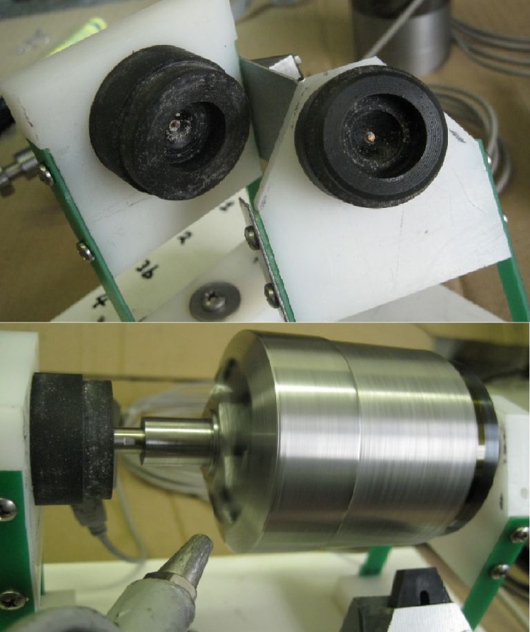
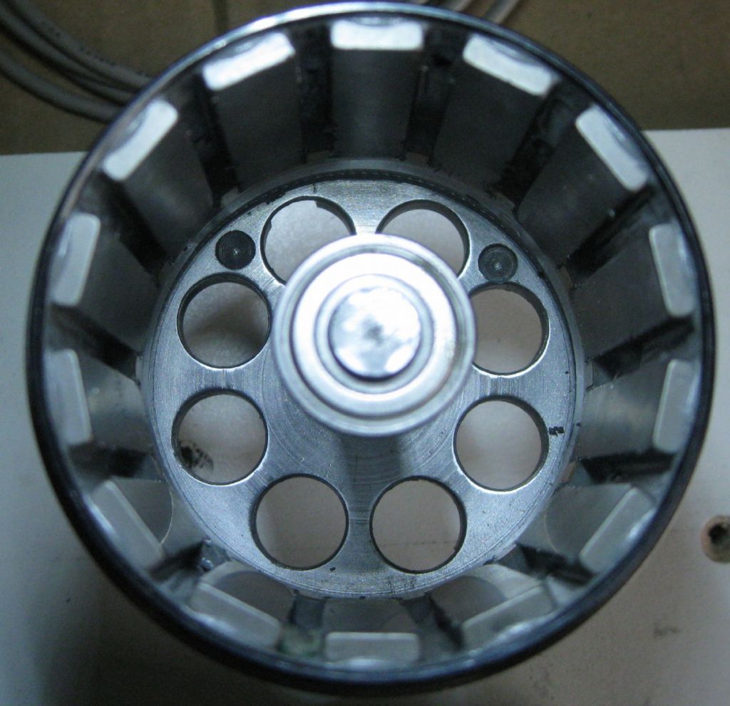
        The motor Rotor/Housing is complete – just finished dynamic balancing of it at 8000RPM – worked out nicely. Have created a separate post on the balancing – this post is becoming a bit of a saga..

        air spinning and bearing housings.jpg

        final balance holes.jpg

        Joe

        #563044
        Joseph Noci 1
        Participant
          @josephnoci1

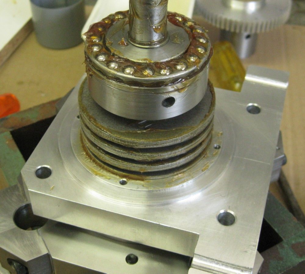
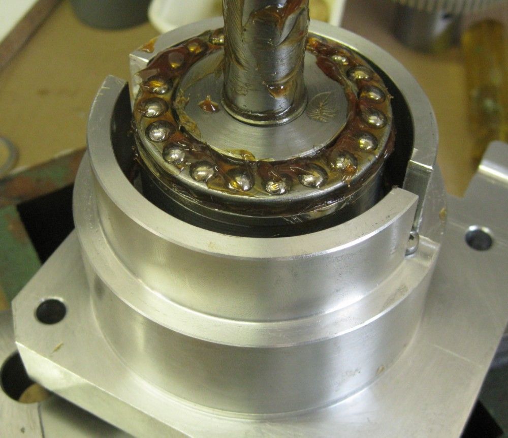
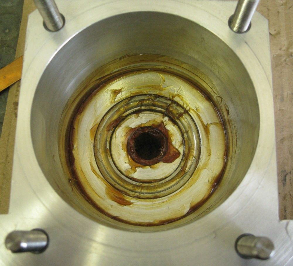
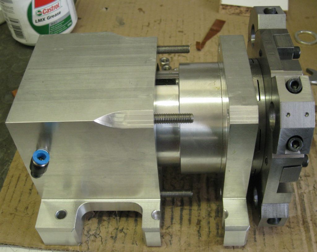
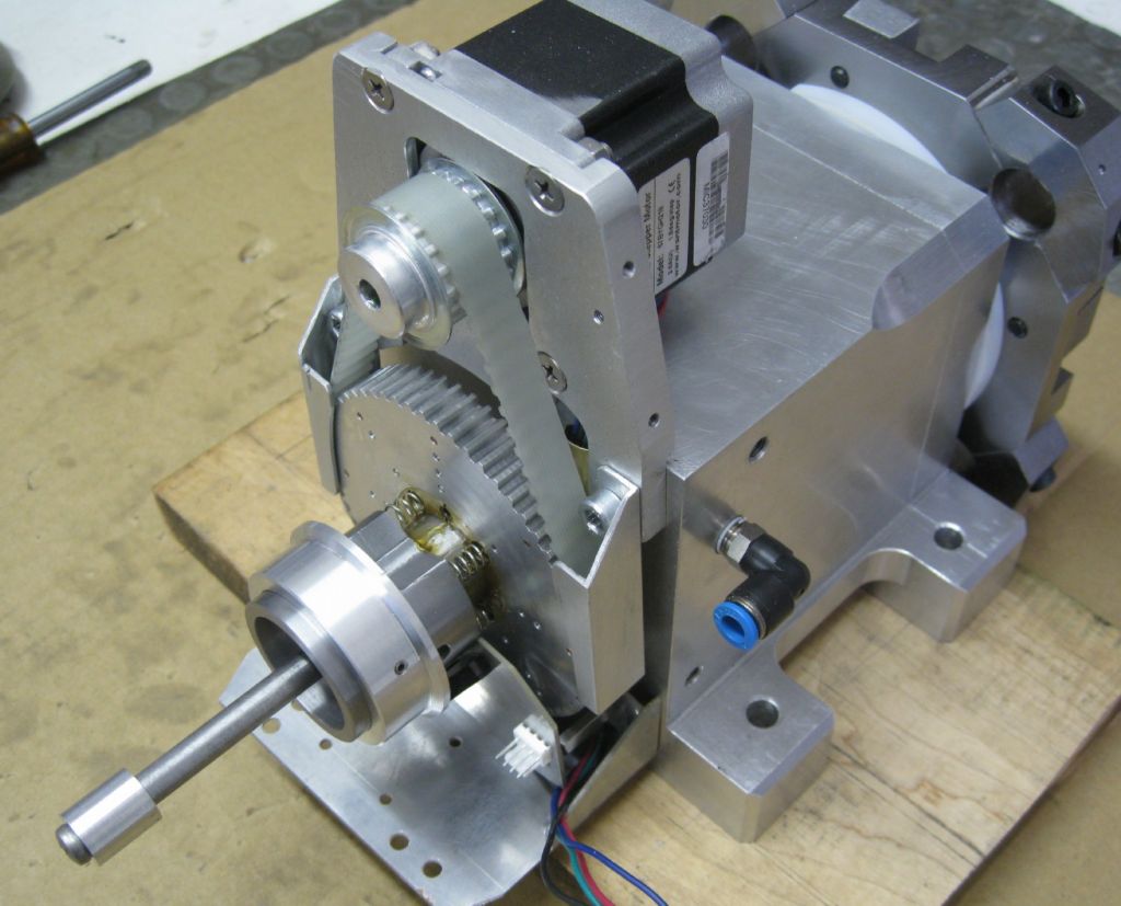
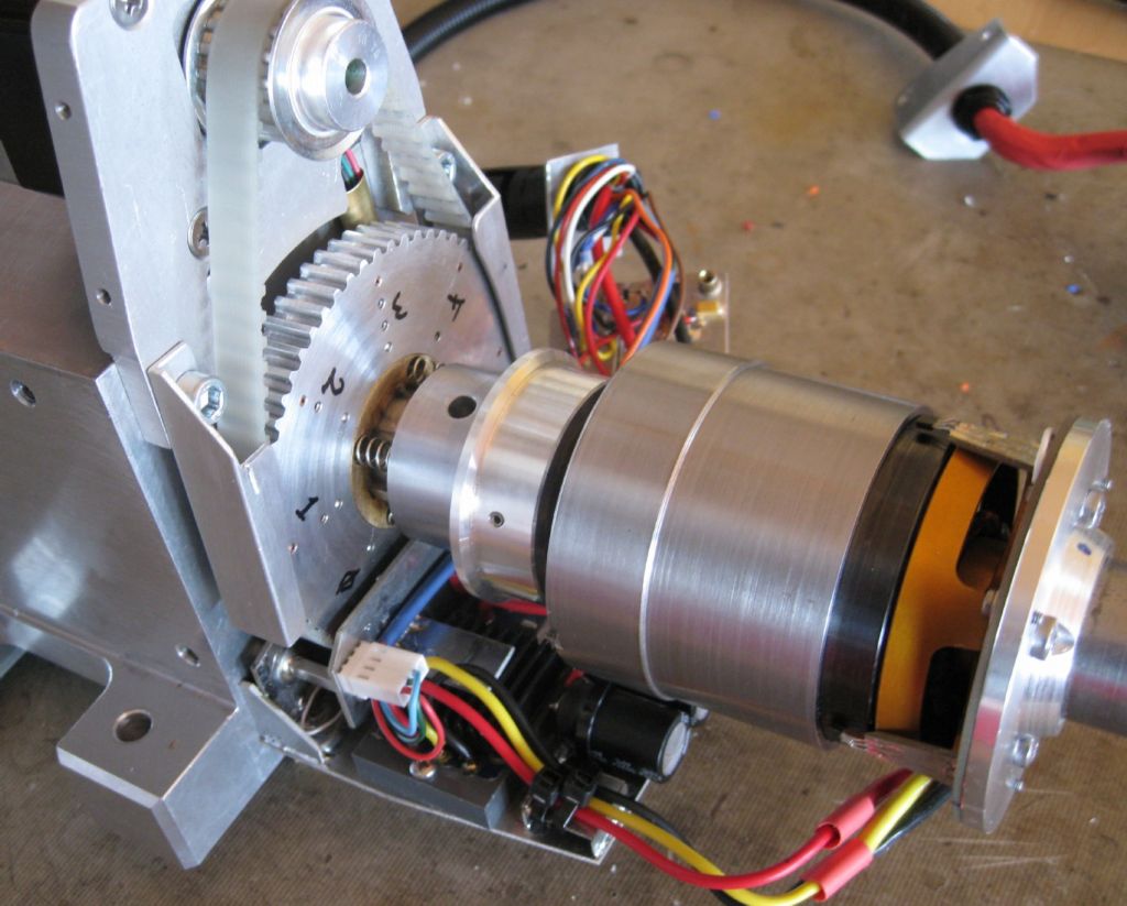
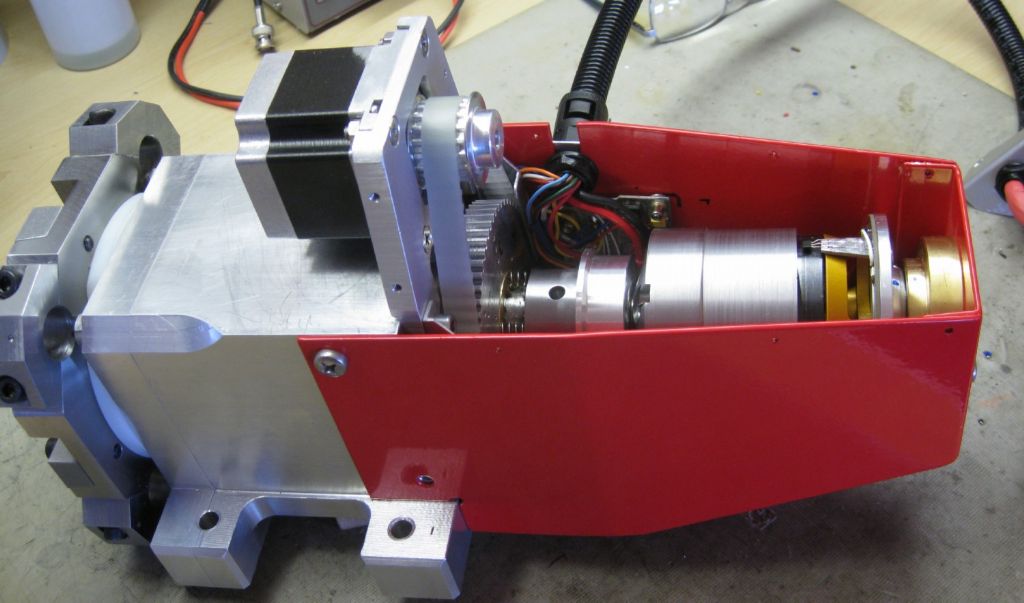
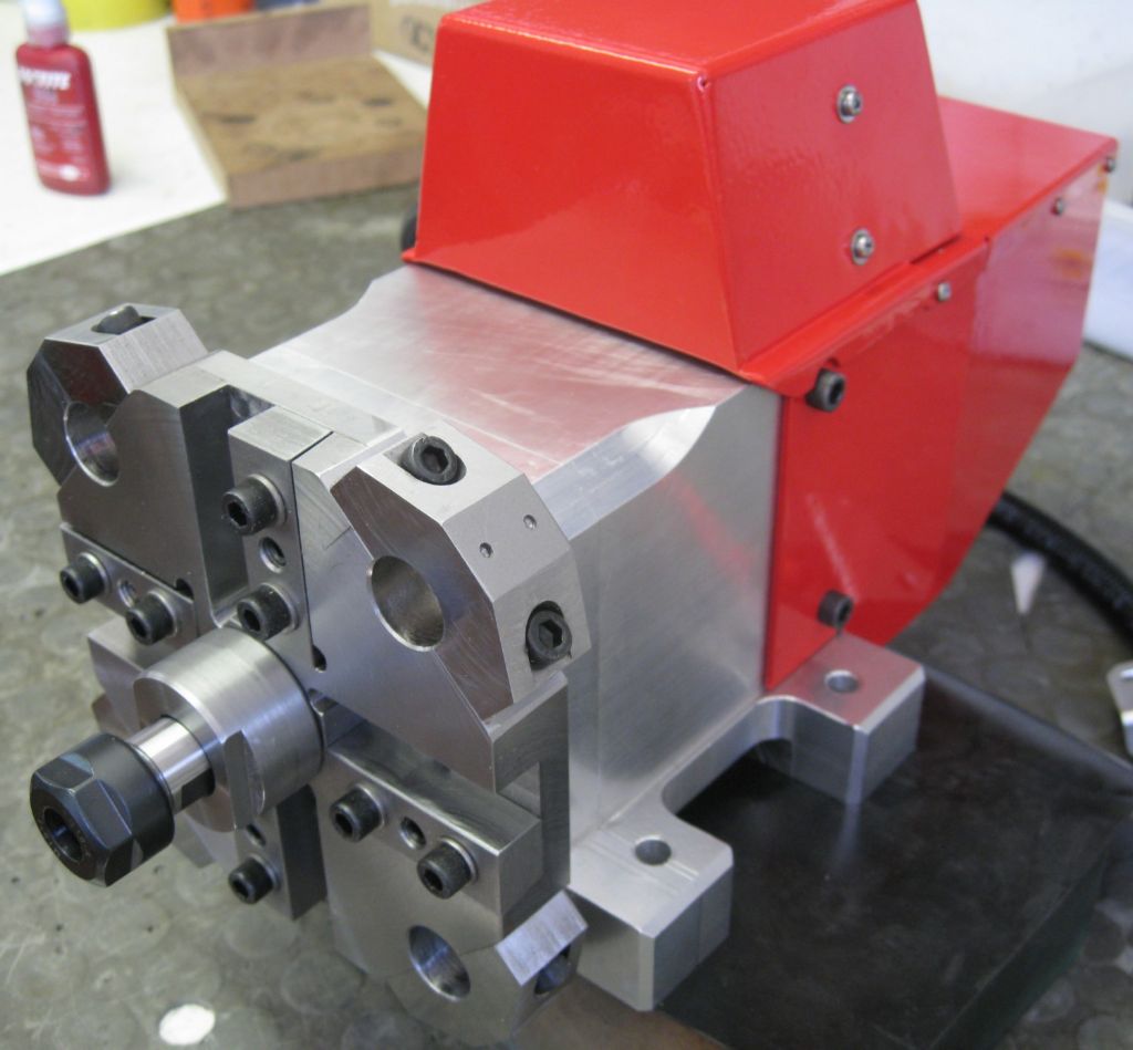
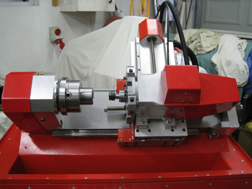
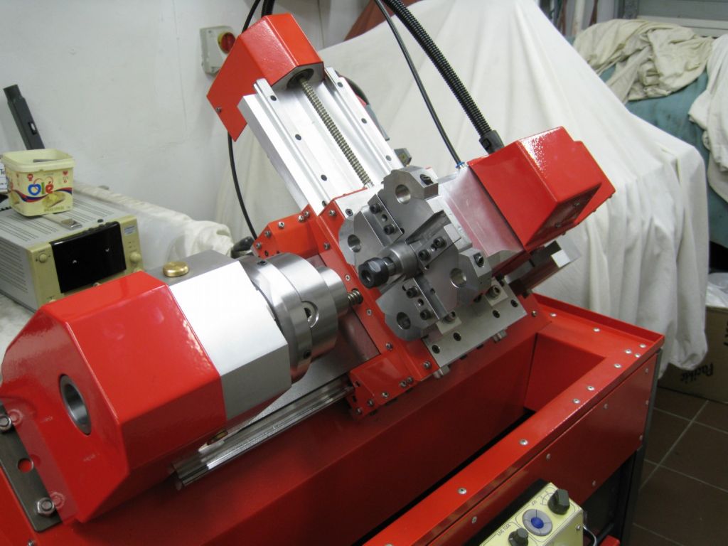
          The ATC is 'complete' – all parts are done and the thing is assembled. I have tested it using a Nucleo with some test code – The Hirth coupling disengages @ 105psi and the stepper turns the tool plate just fine. The live spindle drive also works very well, so all in all I am happy.

          View of the Bellville springs under preload.

          bellville preload.jpg

          Piston travel limiter installed.

          piston travel limter.jpg

          Piston fitted into the cylinder body.

          piston in cylinder body.jpg

          Mating all parts together

          mating parts.jpg

          Live spindle drive shaft installed

          live spindle driveshaft.jpg

          Spindle motor and drive electronics fitted

          spindle motor electronics.jpg

          Main cover fitted

          main cover on.jpg

          All covers on, ready to fit to lathe

          atc closed.jpg

          Views on the lathe

          atc on lathe1.jpg

          atc on lathe2.jpg

          Now the big deal is to get LinuxCNC to talk to the ATC, so I am bum on chair and head buried in the mess of LinuxCNC, HAL and that cryptic world!

          Last post on this lathe will hopefully be a video of it working..

          Joe

          #563101
          Pete.
          Participant
            @pete-2

            Hi Joe,

            I've been quietly following your progress, I know nothing about electronics so can't comment on that side of things, but you've done an amazing job machining all those components and bringing you design to life, I can't wait to see it fired up and put to work.

            Thanks for taking the time to document the process, personally I think it's the best thread on here for ages.

            #563120
            Joseph Noci 1
            Participant
              @josephnoci1

              Thank You Pete. This is not most folk's cup of tea and it is good to receive some comment! Not this forum's idea of 'Model Engineering', and I am considered somewhat anal and excessively fastidious by some….

              On top of that, this project has been, and still is, a challenge. It's scope grew beyond my intentions and the basic capability of most of my machines and challenged me to the point of almost giving up – a few times…Here in Namibia there are NO other folk dabbling in this stuff at all, so cannot even go see someone and lament over a cup of tea, or a barrel of beer!

              Thanks for the encouragement.

              Joe

              #563124
              Ady1
              Participant
                @ady1

                wow, can't wait to see it working

                I would work on lumps of balsa wood for a while, until I was really really sure

                Surely deserves a writeup on lathes.co.uk this one

                #564341
                Joseph Noci 1
                Participant
                  @josephnoci1

                  Well, nothing useful to report, other than that I am feeling somewhat like a piece of threaded rod at the moment…

                  It turns out that when I started this project, the future dilemma would, and did, lie in the fact that success was 'doomed' as I did not know what I did not know. And to discover what you don't know only seems to come about when the task in front of you demands that you dig deep and research a lot, for days…

                  I was searching for a machine controller that could do lathe C axis with live tooling, and did not realised what I should have asked was – C axis with live tooling AND polar interpolation…

                  Many climbed in and said to persevere with LinuxCNC as it 'can do anything' – but if you search ( exhaustively!) you find NO one has actually done this with LinuxCNC…

                  Bottom line is that LinuxCNC CANNOT do Polar modes – it lacks the kinetics, and so lathe polar work is not possible with Polar style Gcodes. And Polar Gcodes are what is generated by ALL the CAM packages I have looked at, tried, trialled and cried over.

                  All CAM packages that deal with Caxis/live tool lathes generate a G12.1 code which sets a suitable controller into polar mode and which then does the Cartesian/polar math. For this to work with LinuxCNC the CAM package would have to convert all coordinated Caxis/Xaxis polar moves to small line increments of angle and x Axis move commands. I have not found any package that can do it! 'Someone' siad F360 can, but did not have the time to test a simple case for me…I also understand that F360 Lathe post-processor has 'warts'…?

                  I had a few CAM companies looking at the issue – it took some doing to get them to understand the issue – they could not get past the disbelief initially that a lathe CNC controller could not do Polar motion…These are companies whose CAM costs between $2000.00 and $4500.00 per seat..Out of 5 companies, 2 were very helpful they even phoned me here in Namibia a few times for more details – I was so frustrated that I was 'sort of' considering paying such a price for something that would work and explained such. They went away and came with a proposal to add the non-polar piece wise Gcode stream – cost to add would be around $2500.00 plus some TBD cost to adapt a postprocessor for the lathe…

                  So I thanked them for their time, and thats that!

                  I do not like F360 – it is to complex to live with – if you don't use it for a few months, it takes a day to get back into it, re-learn the syntax and commands, etc – and they keep changing it – also dislike very much the user use-case and cloud base nonsense…So if someone who knows F360 well is prepared to do a small test code for me, I would be most appreciative – if it works maybe i'll purchase a license…- this may be my only solution bar one – this being that I write my own polar kinematics for linuxcnc and somehow integrate it with some new Gcodes (G12.1/G13.1), etc. That is such a mission – it was supposed to be a user adaptable tool, not a project unto itself!

                  Bah!

                  At least the mechanics are successful – the ATC works well and the whole thing works well as a 2 axis lathe!

                  #564352
                  John Haine
                  Participant
                    @johnhaine32865

                    By polar code, do you mean using the spindle as an A axis? Could you not adapt a milling profile for when you want to do this?

                    #564360
                    blowlamp
                    Participant
                      @blowlamp

                      This is from the PlanetCNC gcode reference – I don't know if it's of any help, I'm just posting if you weren't aware.

                      Martin.

                      G15 – Polar Coordinate Cancel
                      Usage: G15
                      Cancel polar mode coordinate positioning.
                      Parameters:
                      #<_polarmode> – (RW) current polar mode
                      G16 – Polar Coordinate Enable
                      Usage: G16
                      Enable polar mode coordinate positioning. In the polar coordinate mode movement end points are
                      specified as a radius and angle. Origin is determined by the absolute/incremental position mode
                      setting.
                      The current plane setting determines which word is radius and which is angle.
                      G17 – XY Plane – X is radius, Y is angle
                      G18 – ZX Plane – Z is radius, X is angle
                      G19 – YZ Plane – Y is radius, Z is angle
                      Parameters:
                      #<_polarmode> – (RW) current polar mode
                      Example:
                      (square with corners -30,-30 and 30,30)
                      G0 X0 Y0
                      G16
                      G00 X42.4264 Y225
                      G01 X42.4264 Y135
                      G01 X42.4264 Y45
                      G01 X42.4264 Y315
                      G01 X42.4264 Y225
                      G15

                      #564382
                      Joseph Noci 1
                      Participant
                        @josephnoci1
                        Posted by John Haine on 26/09/2021 14:32:29:

                        By polar code, do you mean using the spindle as an A axis? Could you not adapt a milling profile for when you want to do this?

                        John, the spindle is actually the C axis in a lathe, but the principle is similar. And no, you can't adapt a milling profile – or I suppose you can, but you have to unwrap the c axis required motion into a Y axis linear motion and convert that to C axis motion coordinated with X…! So no, not really..

                        #564384
                        Joseph Noci 1
                        Participant
                          @josephnoci1
                          Posted by blowlamp on 26/09/2021 15:58:05:

                          This is from the PlanetCNC gcode reference – I don't know if it's of any help, I'm just posting if you weren't aware.

                          Martin.

                          G15 – Polar Coordinate Cancel
                          Usage: G15
                          Cancel polar mode coordinate positioning.
                          Parameters:
                          #<_polarmode> – (RW) current polar mode
                          G16 – Polar Coordinate Enable
                          Usage: G16
                          Enable polar mode coordinate positioning. In the polar coordinate mode movement end points are
                          specified as a radius and angle. Origin is determined by the absolute/incremental position mode
                          setting.
                          The current plane setting determines which word is radius and which is angle.
                          G17 – XY Plane – X is radius, Y is angle
                          G18 – ZX Plane – Z is radius, X is angle
                          G19 – YZ Plane – Y is radius, Z is angle
                          Parameters:
                          #<_polarmode> – (RW) current polar mode
                          Example:
                          (square with corners -30,-30 and 30,30)
                          G0 X0 Y0
                          G16
                          G00 X42.4264 Y225
                          G01 X42.4264 Y135
                          G01 X42.4264 Y45
                          G01 X42.4264 Y315
                          G01 X42.4264 Y225
                          G15

                          Hi Martin. Unfortunately , not really.. G16 initiates Polar mode but in XY plain, and so intended mainly for XYZ axis machines such a mills. What G12.1 does on a Polar modes equipped lathe is take the polar Y modes of the XYZ machine and convert the motion to X linear and C axis rotation, wrapping what was Y axis linear around the C axis.

                          The key lies in your last bits of the post –

                          G00 X42.4264 Y 225
                          G01 X42.4264 Y 135
                          G01 X42.4264 Y 45
                          G01 X42.4264 Y 315
                          G01 X42.4264 Y 225

                          Still all linear moves, just computing the XY position in polar form…

                          The only way forward I see is for me to write my own full Polar Interpolation kinematics.


                          Edited By Joseph Noci 1 on 26/09/2021 20:07:36

                          #564398
                          Michael Gilligan
                          Participant
                            @michaelgilligan61133

                            Joe,

                            It’s way out of my league … but I just remembered downloading this a while back: **LINK**

                            https://www.researchgate.net/publication/257337791_A_CNC_program_module_based_on_polar_coordinate_system

                            … It may be of more use to you than it has been to me blush

                            MichaelG.

                            #564420
                            John Haine
                            Participant
                              @johnhaine32865

                              Joe, am I missing something here? On my mill under Mach3 the rotary axis is A, and can make coordinated moved with any of the other 3 axes. The A axis is calibrated in degrees,. I guess if your CAM insists on making C axis moves you could just do a global edit on the g code?

                              John.

                              #564439
                              Joseph Noci 1
                              Participant
                                @josephnoci1

                                Hi John,

                                Here is where one has to get you mind wrapped around the issue ( or the axis)…Also why I am only discovering the issue now, since as I mentioned before, you really only learn when you need to, not in passing..!

                                Anyway – The motion you speak of is essentially still just linear.

                                In other words, when you issue G01 X10.00 A10.00the two axes will move to 10mm and 10deg coordinated. So when A has move 1deg, X has moved 1mm, etc. The two axes will accelerated together, travel together and both decel to the 10mm/10deg finish line together. That's coordinated, not interpolated in the true sense.

                                This works identically in the C axis lathe – A G01 X10 C10.00 will do as your mill did.

                                Now Imagine cutting a square head on the end of a shaft in a Caxis/live tool lathe – It is educational to visualise the actual C axis / X axis movement relationships in travel as the path is cut – the path is non-linear, sort of Hyperbolic.

                                If the CAM packagedid the interpolation and then generated Gcode that was simple coordinated 'linear' moves, ie, many short G01 Xxx Cyy moves, then each move would be coordinated and the actual cut path alone one side of the square would be done by hundreds of such G01 moves – Caxis would rotate a tiny bit and X would likewise move a tiny bit, etc.

                                But CAM packages that are capable of C axis/live tool lathe camming tend NOT to generate such piece-wise code – they use 'interpolated modes' – They issue a G12.1 (or similar) which places the controller in polar mode. Then the issues Gcode are a specific notation of X and C axis moves, which if the G12.1 were not active, would make the two axes simply move in coordinated motion as the examples above – the path followed would not be along the side of the square at all! The G12.1 makes the controller looks at the X/C move command and do a linear to polar conversion to establish the path, and back to cartesian coordinates to then move each axis in normal coordinated mode, in very tiny increments, many thousands, compared to the hundred in the example above.

                                A long story…!

                                Hope that explains a little?

                                #564463
                                blowlamp
                                Participant
                                  @blowlamp

                                  It looks like Centroid make a C-Axis controller, but at a price. You'd be looking at around $2300 for the board & software.


                                  Martin.

                                  Edited By blowlamp on 27/09/2021 14:29:31

                                  #564478
                                  Joseph Noci 1
                                  Participant
                                    @josephnoci1
                                    Posted by blowlamp on 27/09/2021 14:28:16:

                                    It looks like Centroid make a C-Axis controller, but at a price. You'd be looking at around $2300 for the board & software.

                                    Martin.

                                    Yes, they do. Centroid was my first port of call, with a near_purchase…It does implement a C axis and was told it would do what I want, but turns out that was not so – It does exactly what my LCNC setup as at present does – NO Polar Interpolation, no G12.1/G13.1. As with mine, it can only do C axis Indexing and coordinated moves. So you can drill holes on the face of a part at any angle, using the live spindle, etc, but no polar stuff..I searched for a controller or software to do this…Considering the pain en-route to what I have, I would have happily paid $3K for an of-the shelf option!

                                    Joe

                                    #564491
                                    John Haine
                                    Participant
                                      @johnhaine32865

                                      I'm still not quite getting this. CNC systems usually have circular/conical interpolation so you can ask it to move in a circle or helix and the controller directly generates the XYZ moves to do this without going through a g-code step so the huge overhead of g-code interpretation is not required. Is what you are asking for in effect a generic interpolation mode, where for example it could move to follow a suitably defined curve without going through g-code?

                                      #564498
                                      Michael Gilligan
                                      Participant
                                        @michaelgilligan61133

                                        Did the brief paper that I linked miss the point completely ?

                                        … Just trying to learn a little from your adventure.

                                        MichaelG.

                                        #564529
                                        Joseph Noci 1
                                        Participant
                                          @josephnoci1

                                          Michael, that paper is exactly the issue and the guts of that paper is precisely the core of what I would need to implement, Unfortunately, as with most papers, they provide the gravy and very little, if any, meat! However, its not really to complex, especially if I limit the function to basics. We will see…

                                          Interesting paper though – positioning accuracies of 6um, etc…!

                                          Joe

                                          Edited By Joseph Noci 1 on 27/09/2021 20:41:55

                                          #564532
                                          Joseph Noci 1
                                          Participant
                                            @josephnoci1
                                            Posted by John Haine on 27/09/2021 17:50:11:

                                            I'm still not quite getting this. CNC systems usually have circular/conical interpolation so you can ask it to move in a circle or helix and the controller directly generates the XYZ moves to do this without going through a g-code step

                                            In fact this IS the Gcode step – It is the Gcode that tells the controller to do the interpolation, and the controller does all the math to create the cartesian moves and steps for the steppers/servos.

                                            so the huge overhead of g-code interpretation is not required.

                                            Not sure what you mean here – there is 'huge' overhead right here, but it is in the crunching capability of the controller – it has to do all the math after interpreting the Gcode or command.

                                            Is what you are asking for in effect a generic interpolation mode, where for example it could move to follow a suitably defined curve without going through g-code? —-NO

                                            Difficult for me to explain – I lack the correct terms and the appropriate math insight!

                                            The Gcode G02 X Y I J allows the mill to generate in interpolated ARC in the XY plane.This will cat an arc in the material at the appropriate position.

                                            If that Gcode is preceded by G17, the ARC is in the XY plane, by G18, the arc will lie in the XZ plane, etc.

                                            Similarly G02 X Z I K generates an interpolated arc on a lathe in XZ plane, but that arc is an XZ move, such as an arc on the end of a shaft in the chuck.

                                            If you use a rotary axis in the mill, and constrain the Y axis (as in a lathe) , the lost Y axis has to be wrapped around the A axis and you would have to use a Gcode along these lines

                                            G02 X A(angle) I J – this is then POLAR interpolated from Y to A to generated that curve. If you machine does not have that interpolater mode it will not work. J is for XY plane

                                            Polar interpolation on the lathe is similar, but 'not quite' – 

                                            For example here is the basic code to mill a 40mmx40mm square on the end of a shaft:

                                            G12.1
                                            G42 G0 X60. Z-5. C0. F.(feedrate)  # this line is the initial; position of X and Z ( and C = Y )
                                            G01 X40.
                                            C20.
                                            X-40.
                                            C-20.
                                            X40.
                                            C0.
                                            G40 X60.
                                            G13.1
                                            G0 Z10. M05

                                            The C axis is not given in angles or arcs – you treat it like a Y axis, cartesian position.

                                            So read that file with Y instead of C, for a milling machine and it is basic XY move from corner to corner.

                                            But the G12.1 Polar mode causes the controller to convert the 'Y' position to a set of cordianted C axis and X moves…

                                            Joe

                                            Edited By Joseph Noci 1 on 27/09/2021 21:42:25

                                            Edited By Joseph Noci 1 on 27/09/2021 21:42:50

                                            #564574
                                            John Haine
                                            Participant
                                              @johnhaine32865

                                              **LINK**

                                              https://www.kadirilkimen.com/thepolarbear/

                                              Could this open-source project be useful?

                                              #564579
                                              blowlamp
                                              Participant
                                                @blowlamp
                                                Posted by John Haine on 28/09/2021 10:02:27:

                                                **LINK**

                                                https://www.kadirilkimen.com/thepolarbear/

                                                Could this open-source project be useful?

                                                That looks interesting, John.

                                                There's also a 'Polarizing Converter' that may be of some use to Joe here. There is no 'C' axis label available, but if the basic conversion is OK, then it might be a simple Search & Replace in Notepad.

                                                Martin.

                                                #564604
                                                Joseph Noci 1
                                                Participant
                                                  @josephnoci1

                                                  The method chosen by the PolarBear designer is to post-convert a standard, non-polar Gcode file into cartesian and angular segments. That is as we discussed in our posts. To expand on the downside – A polar interpolation kinematic would interpret the polat Gcode commands and generate output 'commands' ( step pulses, ie, the smallest resolution increment possible on a given machine) driving the axes along the cut path. To obtain that same resolution ( which you DO need if you look carefully at the hyperbolic path motion for our square in the C axis) in a post-processed Gcode file would mean thousands, maybe 10's of, Gcode lines converting Polar to small coordinated X and Caxis moves. In addition, the surface finish suffers because the feed rate cannot be properly interpolated down to individual Gcode moves, and so impossible to maintain any constant feed rate or material removal rate.

                                                  In the standard Caxis/Xaxis G12.1 interpolation, feed rate is normaly inverse time as well, which gives constant cutting edge feed, while the Caxis motion rate can vary hyperbolically

                                                  See what Polarbear says..

                                                  I had to develop a postprocessor for g-codes:

                                                  **LINK**

                                                  This postprocessor imitates the polar movements that would be run by a cartesian controller. This works great too. But it is not efficient. It generates twice or more g-codes and it cannot run the machine at efficient feed rates. Even if we calculate the best feed rates, the firmware will treat the movements as cartesian and recalculate the decelerations and accelerations, which would be wrong for polar motions.

                                                  Therefore, without special firmware for polar and cross slide motion, the machine often runs at inefficient feed rates.

                                                  My brain is so wrapped around this C axis at the moment…head spinning.

                                                  #564607
                                                  blowlamp
                                                  Participant
                                                    @blowlamp

                                                    Surely this would do it? smiley

                                                    Edited By blowlamp on 28/09/2021 12:46:59

                                                    #564612
                                                    Joseph Noci 1
                                                    Participant
                                                      @josephnoci1
                                                      Posted by blowlamp on 28/09/2021 12:46:39:

                                                      Surely this would do it? smiley

                                                      Edited By blowlamp on 28/09/2021 12:46:59

                                                      Sent a request for the supported Gcode list – lets see!

                                                      Joe

                                                    Viewing 25 posts - 126 through 150 (of 173 total)
                                                    • Please log in to reply to this topic. Registering is free and easy using the links on the menu at the top of this page.

                                                    Advert

                                                    Latest Replies

                                                    Viewing 25 topics - 1 through 25 (of 25 total)
                                                    Viewing 25 topics - 1 through 25 (of 25 total)

                                                    View full reply list.

                                                    Advert

                                                    Newsletter Sign-up