Ok, back to work…
Duncan, I think I follow your idea – makes sense and I will see down what road that all takes me..
This thing is certainly taking me down many a painfull track!
Still fighting the tool changer – still have not receive the Bellville springs from SA..
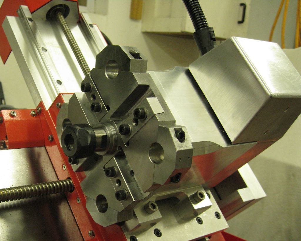
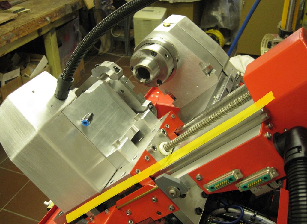
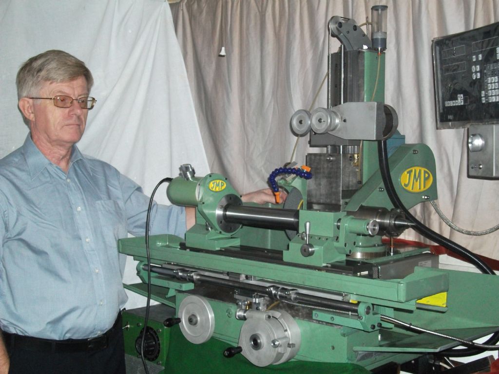
So I started think about the live tooling or milling spindle. The ATC is small, so not easy to incorporate conventional live tooling. I would like to have a radial and axial milling capability, but that means swinging the milling spindle around, and doing that servo-ed is not really feasible on the cross slide, space, etc. Manual swiveling is ok, since milling on the C axis is not done often. I considered 2 milling heads, at 90deg – the axial head can remain in place and will ( should..) not crash, but the radial head must be removed at times..all together a pain in the butt!
Then I thought if I made the axial spindle coaxial with the ATC main shaft, it would free up space in front of the ATC and allow the radial spindle to be fitted there somewhere.
And so the hack began…
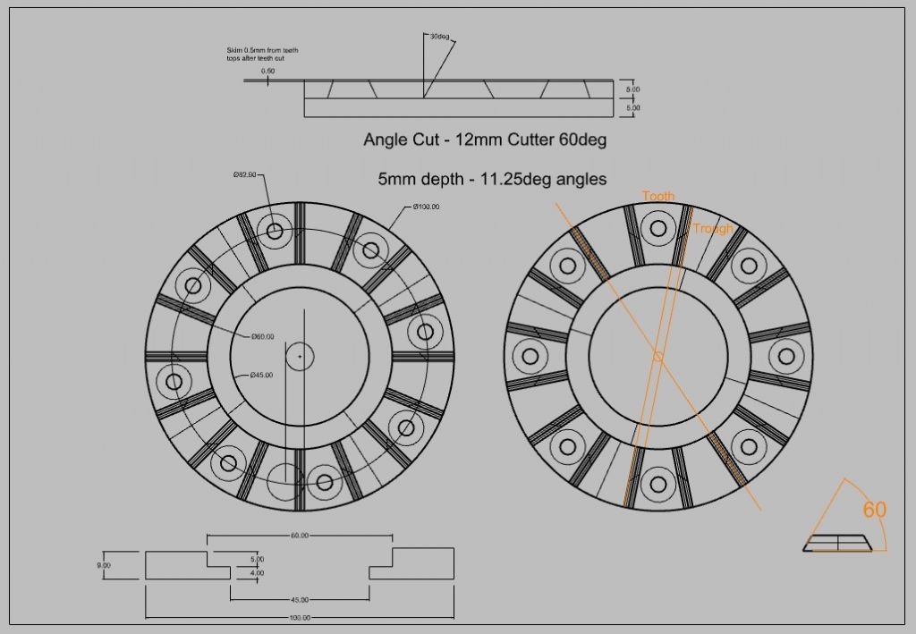
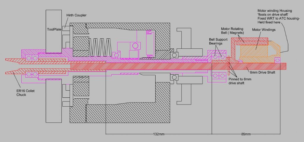
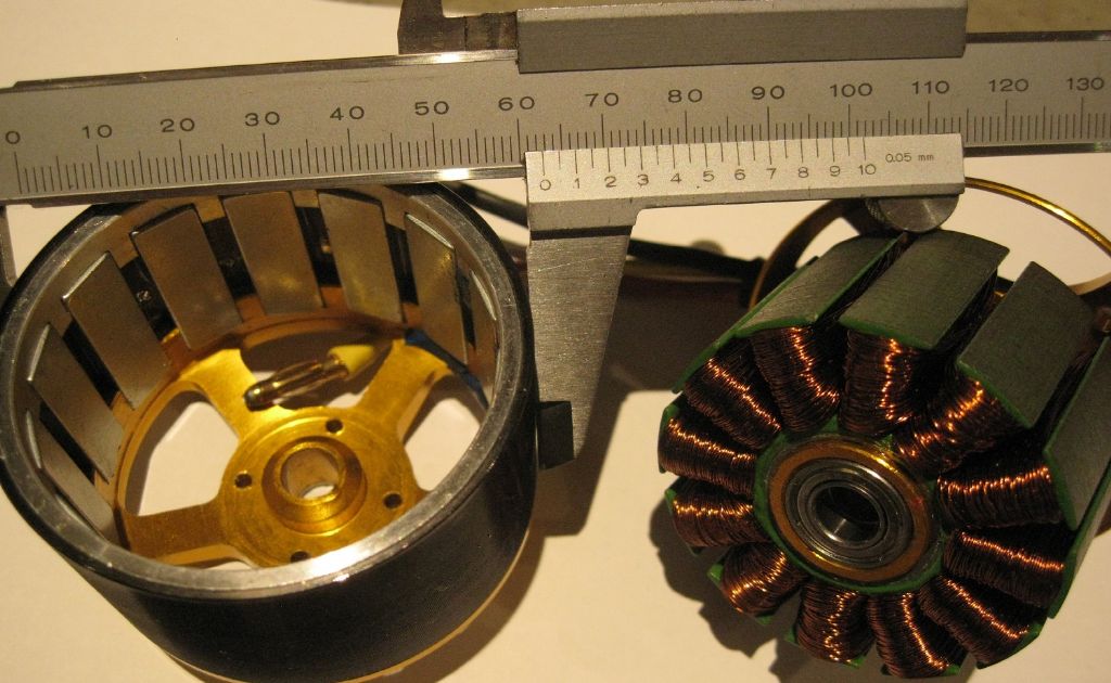
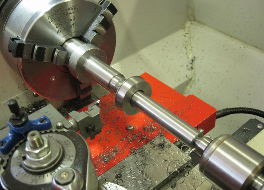
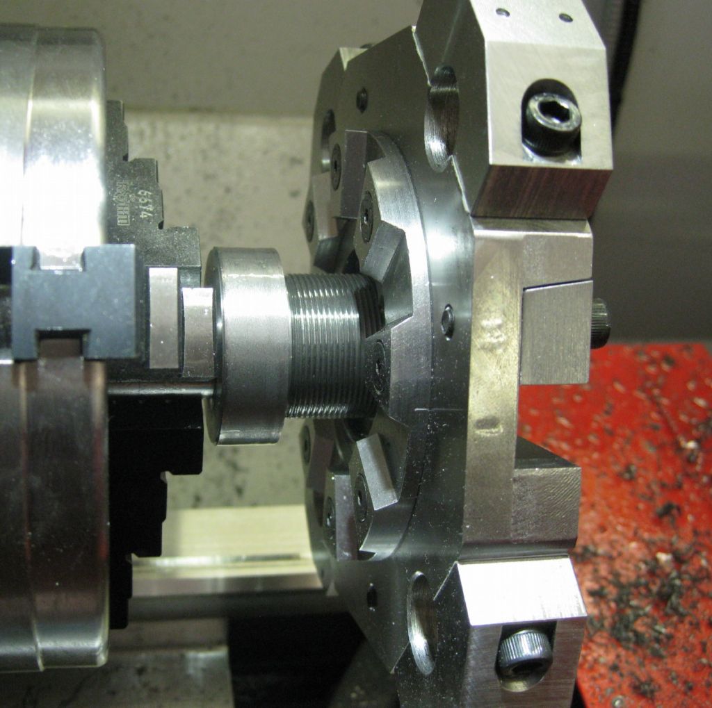
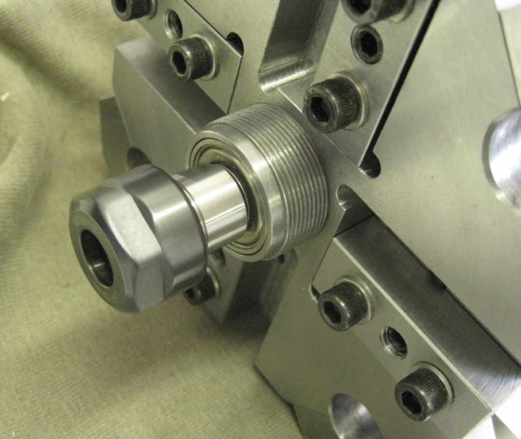
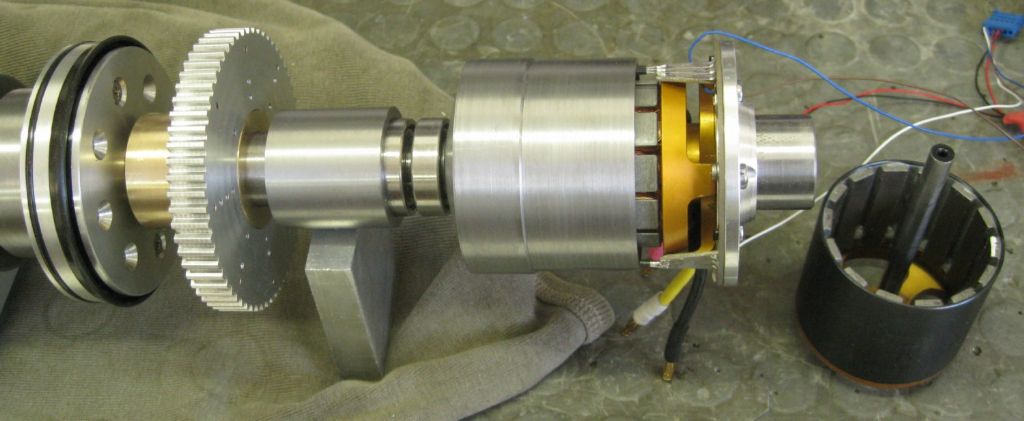
The 9th toolstation was the ER20 Chuck in the ATC toolplate center ( see previous pics..) – the idea was to remove that, and fit bearings carrying an ER16 chuck, with the chuck drive shaft through the ATC main shaft, out the rear and driven by a BLDC motor at the rear.

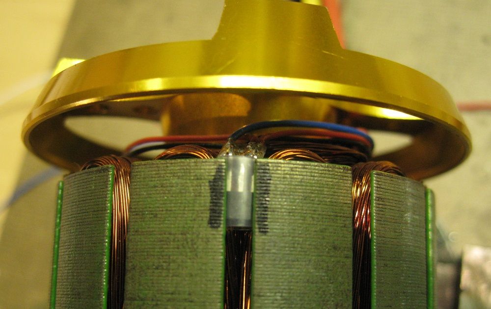
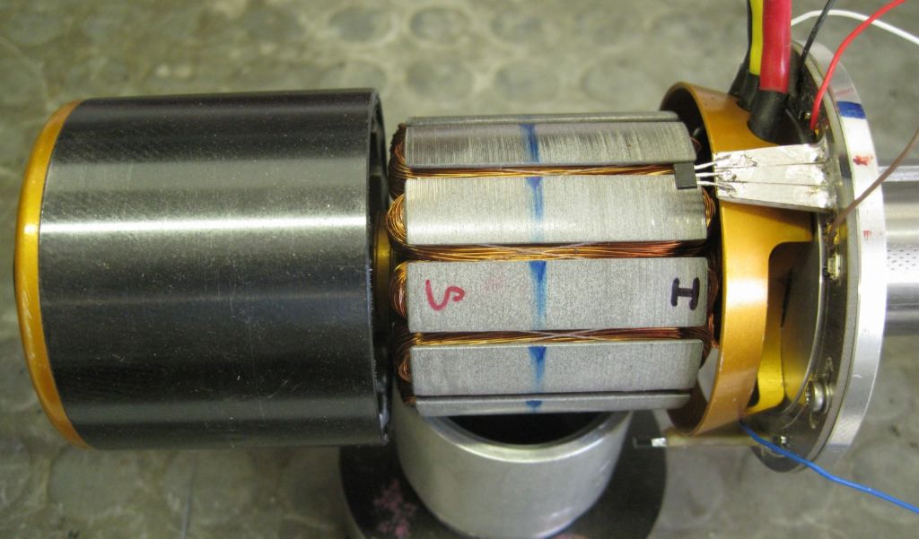
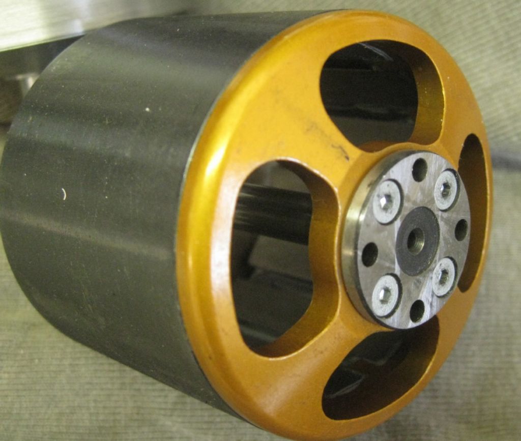
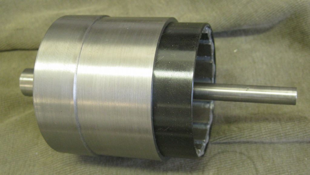
The RED parts are the milling spindle and spin together. The Lilac parts are the ATC main shaft and are static, except when changing tools – they then rotate to new tool position, and slide left to clear the HIRTH coupler before rotating. On the right is the BLDC motor Bell housing ( contains the motor magnets) which is pinned to the 8mm spindle drive shaft. It is supported by the Bell Support Bearings ( Lilac). The Orange parts on the right are the BLDC motor Windings and rotor(?) core, on bearings, on the 8mm drive shaft. This orange section is constrained from rotating, by a sliding retainer ( not shown) fixed the ATC housing. The orange section, Red and Lilac sections are slide left to clear the Hirth coupler during a tool change.
The 8mm drive shaft has a free length of 132mm.
I have been trying to model what sort of torsional mode will arise in that section when milling – vibration, resonance, etc, but have given up! Very difficult to find data on milling cutter energy needed for an milling edge to cut say mild steel, given DOC, RPM, etc, etc..and then the resulting twist in the drive shaft, and release of that wind-up when the cutting edge clears, etc..
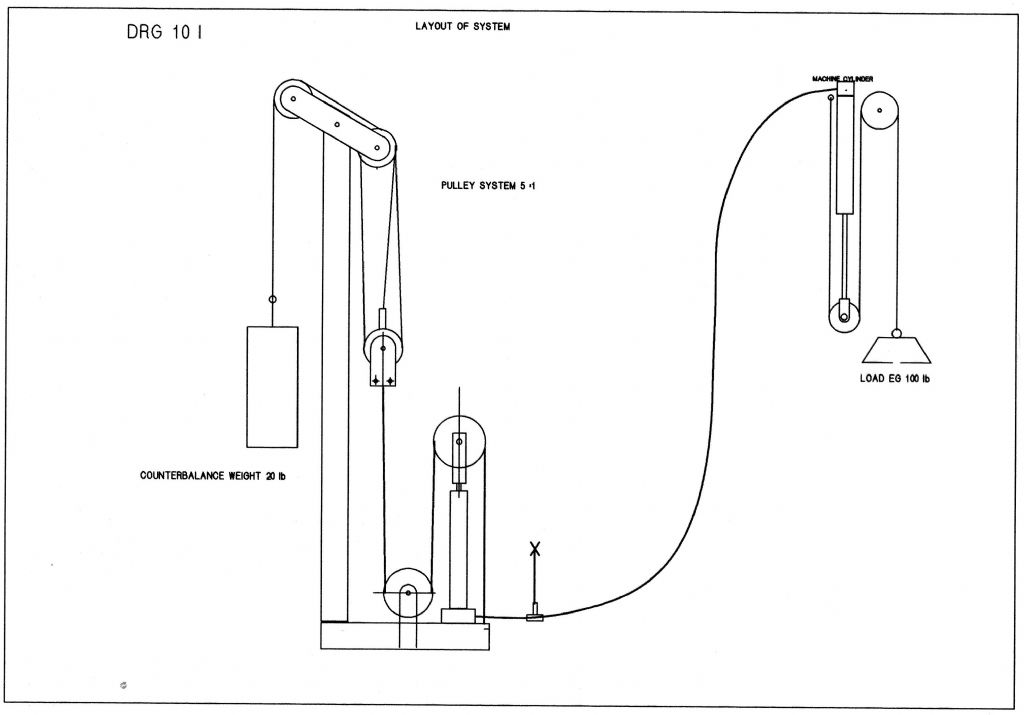
I cannot go larger than 8mm on that drive shaft – increasing means increasing the through hole in the pneumatic piston for the Bellville spring compression. That means less piston surface area and more air pressure needed. I am trying to stick below 110PSI – if you followed the discussion previously in my posts you will know the reasons behind said pressures..
The milling process is low key – not high rate of metal removal, etc.
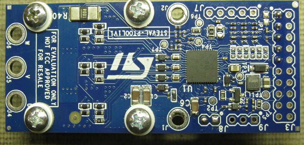
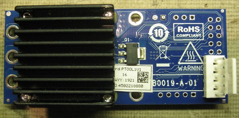
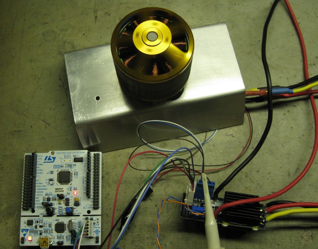
The BLDC motor is a 400watt motor- 400watts for 60sec it says.. 250watts cont. The largest milling cutter would be 8mm, probably 6mm. The lowest useful spindle RPM would be 300rpm and the highest around 5000rpm. The BLDC motor is capable of 5000rpm at 45VDC supply.

Am I wasting my time???
Joe
sam sokolik.


