CNC Lathe Scratch Build
CNC Lathe Scratch Build
Home › Forums › Work In Progress and completed items › CNC Lathe Scratch Build
- This topic has 172 replies, 28 voices, and was last updated 25 August 2022 at 18:08 by
sam sokolik.
-
AuthorPosts
-
26 April 2021 at 22:06 #541775
Joseph Noci 1
Participant@josephnoci1Posted by Ross 77 on 26/04/2021 13:25:42:Joe
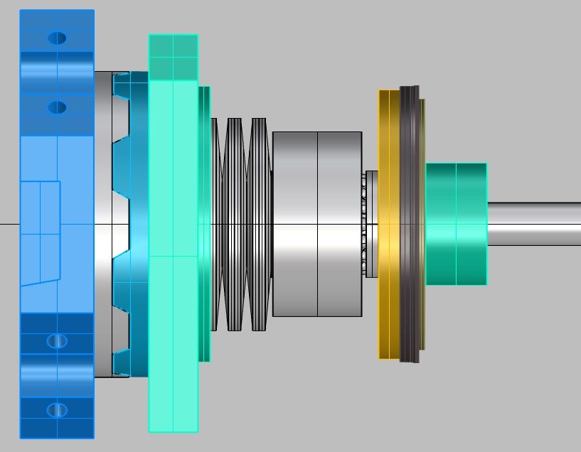
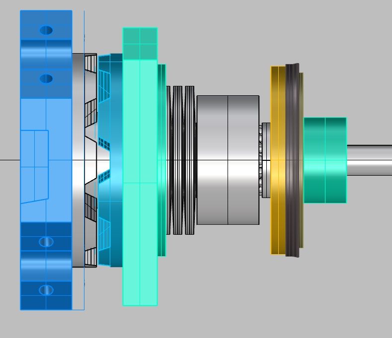
I think 8mm of travel would cause you problems with the bellevilles by raising the opening force. we had 4mm tooth height and 1mm clearance so total travel of 5mm. that was generating a lot of force to reach the opening distance.
Martin
The coupling is quite easy to machine on a rotary table if you do full passes, then it is only 8 changes. T.B mentioned early that any error isnt really a problem as it is always repeatable.
Ross,
The 8mm teeth were just a modelling test – far to tall. What is the actual contact height ( axial height) of the teeth in your design? Around 3mm? – 4mm tooth height with what seems to be about 1mm between tooth crest and opposite trough?
What sort of milling cutter did you use? seems to be an angled cutter with a carbide insert?
The rotary table seems to be horizontal, so cutter is angled.
How did you do 'full pass' machining? Milling the flank of a tooth would require the cutter to be offset , say, to the left of the tooth flank, and then past the tooth, to the center of the disc, where the offset would need to be shifted to the right of the flank of the opposite tooth ( the tooth @ 180degrees).
I glibly thought to use my shaper to do full pass cuts – Not Possible!
Joe
Edit – text changes
Edited By Joseph Noci 1 on 26/04/2021 22:08:30
27 April 2021 at 00:53 #541790Ross 77
Participant@ross77Joe
Ah sorry I must have miss read your comment, Id have to measure the contact height to know for sure but I though it was closer to 4mm but yes that sounds about right with 1mm clearance on the peaks and troughs.
It was an angled cutter that was modified to have a flat bottom. a pointed cutter didn't work very well. the cutter was measured and then had the tip ground down and remeasured. the difference was used to work out the new cutter base width for the offsets.
I got the machining process a bit wrong. it was the roughing pass that went full pass (parallel cutter) , then as you say the angled cutter was set up at an offset to mill the flanks. sorry, I didn't do the machining and it was a while ago. I just had to work out all the offsets to set the DRO on the mill

I did wonder how you were going to use the shaper. Rotary table seems the easiest.
1 June 2021 at 15:22 #548009Joseph Noci 1
Participant@josephnoci1A plea to any of the folk who have implemented an ATC on a lathe, using LinuxCNC – I would dearly like to discuss some of the ins and outs please!Maybe T.B. , Ross, Simon?Thanks YouJoe1 June 2021 at 21:12 #548035Ross 77
Participant@ross77Hi Joe
I do use Linux CNC but I'm certainly not an expert user, more of a trial and error code basher and I haven't implemented an ATC yet. I'm going through the same issues with my Boxford and and trying to build a custom interface for the lathe that fits my touchscreen.
I'm using a 7i96 and managed to get it working on the Ethernet and setup with the pc-config. The ATC will be soon but the Boxford one is the ratchet and pawl type so I think there are a few examples already in circulation on the Lcnc forum. I believe its just set up as a rotary axis and no feed back.
What issues are you having?
2 June 2021 at 08:53 #548071Joseph Noci 1
Participant@josephnoci1Hello there,
Thanks for responding – The issues are yet to come I guess – I am progressing well with the manufacture of the ATC – what a lot of work and machining.
While letting the lathe and mill cool down I am trying to get to grips with the ini, HAl and ATC component in Lcnc..I have just a few days ago got he lathe and its C axis working very nicely , thanks to Andy on the Lcnc forums, and so on to the ATC now.
I have dug through all the examples I could find, inc the Carousel setup done by Andy ( lost me though..) and the I found a Hal/ini/comp set of files on Github – I think the original was done by 'arceyes' for a boxford 240 and I believe you modified for the Compact 5 – was under the Machinekit configs.? Not sure if I have this correct.
I would like to try take that set of files and begin understanding how it all works and see if I can make it work with my design, which in essence is the same as the ATC you have made.
However, as Andy found ( to his frustration), I don't get on very well ( at all!) with HAL and Component integration and rather than drive Andy mad again so soon, I thought , if you are doing this already, maybe I could ride on your back for this.
I was going to fit a small proccessor board into the ATC to control it, ie, the stepper, tool position sensing, etc, but Andy said that was a waist as Lcnc would be able to do it all…
Joe
2 June 2021 at 23:20 #548138Ross 77
Participant@ross77Hi Joe
I can definitely confirm that a decent home built ATC is a lot of work
 I think we had about a year invested in ours
I will help were I can and i will be building a similar machine but Andy is the best one to guide you through all this.
have you seen the "the feral engineer" on you tube? The feral engineer – YouTube
he talks through Hal in quite some detail and is on the linuxcnc facebook page if you need one to one.
don't bother with the external processor Lcnc can manage all of that.
what Mesa are you using? if i have a the same card then it will be easier for me to test the HAL and share files.
3 June 2021 at 08:14 #548148Joseph Noci 1
Participant@josephnoci1if i have a the same card then it will be easier for me to test the HAL and share files.
Thank you for the offer.
I am using a 7i92 / 7i76D combination. I also have a 7i73 attached, but that is for jog wheels, user buttons, etc.
The 7i92 provides 4 stepgens – I use three, X/Z/C, and then the last for the ATC
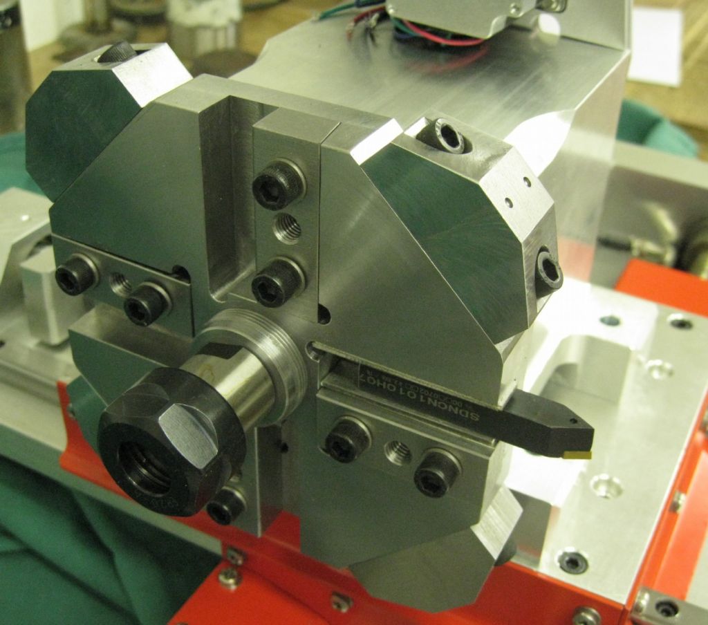
Eventually the ATC would need to handle 9 tools – I have an ER29 collet chuck in the toolplate center, so the 9th tool is ATC centerline aligned with the spindle axis.
I will certainly make use of Andy's kind assistance in the future- I would like to have put in the best effort I can though before I bother him again.
My problem is that HAL confuses me so – I battle to know what is a user define variable, what is part of HAL/Lcnc syntax, signal directions, and why I even need some of those signals…And then how does a component tie into all that as well! I am currently taking the HAL/ini and C_Axis component that Andy divined and 'breaking' it – modifying parameters and seeing what the effect is and so developing an understanding of the how and why. Not the most efficient way, but the Lcnc docs are very good if you know HAL and Lcnc…not for a rookie, that's for sure! My wife and I are both skilled in C, but the 'language' and its constructs in Lcnc/HAl seem to have few rules.
I will do whatever leg work required to learn!
Thanks again…
Joe
Edited By Joseph Noci 1 on 03/06/2021 08:15:56
5 June 2021 at 22:29 #548461Joseph Noci 1
Participant@josephnoci1The Lathe C_Axis is finally working – and very nicely indeed.
Thanks to huge assistance from Andy on the Linuxcnc forums – My contribution was probably 5%, the rest was Andy..
This lathe is a project quite larger than I..
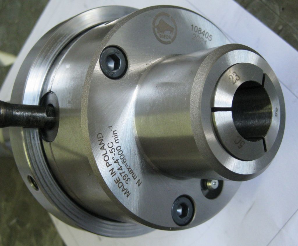
Anyway, since that part is done, It is now worth continuing, and the items in the queue are a new main spindle, to take a 5C collet chuck- received from Bison this week, a very cute 100mm OD 5C chuck. So I need to make a 'set-true' style backplate and new spindle – the current spindle is flush with the headstock, so no place to mount a backplate.
Another item in the queue is the Tool Changer and that is a real mission…Been doing a lot of CAD modelling and believe I have a workable design. I have started rough machining of the big metal bits, save for the main body. Still waiting for pneumatic piston and rod seals, and the belleville springs before that part of the design can be refined.
Side View – Closed Pre-load position – preload approx 2000N
Side View – Open Position – Load approx 4000N – movement 6mm @ 4000N
Edited By Joseph Noci 1 on 05/06/2021 22:30:04
7 June 2021 at 23:09 #548786Ross 77
Participant@ross77Hi Joe
Nice work and I like the combined housing and cylinder bore. We did consider that, but decided the proto should be made up of individual parts so they could be easily changed or modified if they did not work.
Sounds like you are getting there with Lcnc. I have those Mesa cards as well so I will be picking your brains on the C axis implementation.
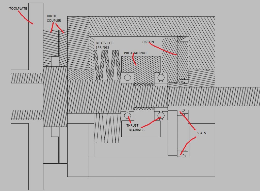
You asked for a critique but I see you are using a different arrangement on the shaft loading and now rely on the trust bearings which is different from our design so I have no experience in that layout and what the pit falls are. I don’t know if it will help but here are a few comments from a fresh pair of eyes and some points that we were looking to work on.
Design checks
- I think you need a clearance gap between the main shaft and the Body front plate to allow the Hirth coupler space to close and fully compress.
- Have you got enough Bellevilles and are they within the 75% max crush?
- The Bellevilles are constrained by their ID on the main shaft which might damage the shaft as the Id changes. On ours I used the piston to constrain the springs on their OD, leaving a clearance space on the shaft.
- Is the front thrust bearing over constrained? The shaft and spring are bearing on the same face.
- Is there a lock nut on the preload nut? Will it work loose over time?
Questions / logic check
- How is this assembled?
- How is the rear bush/piston seal located to stop it from moving when pressurised?
- Do the Hirth teeth have to be so deep? The shear is a the base of the tooth.
- What is the purpose of the spacer that the Bellevilles bear on?
- If the piston is transferring force through the thrust bearing is there chance that it is to slender and will want to cant/ bind in the piston bore?
- Can you use an odd number of bellvilles?
Considerations
- Can the Hirth couplers be machined directly into the tool plate and housing front plate?
- The piston bore only needs to be the last 20-30mm so is it worth enlarging the front section as a roughing cut to save machining time?
- Hirth tooth angle. Look to make this as steep as possible as it helps reduce the axial load so a lower opening force can be achieved. We played safe as a shallower angle helps with any positioning error from the stepper and will still centralise if the motor over runs. In use it seems to stop perfectly.
- Look to reduce the Hirth tooth height as that also reduces the opening force. Having seen a few commercial ones they seem to have quite shallow teeth.
9 June 2021 at 12:36 #549002Joseph Noci 1
Participant@josephnoci1Hellp Ross.
Thanks very much for some very constructive criticism and very good points!
I have adapted the design concept accordingly..
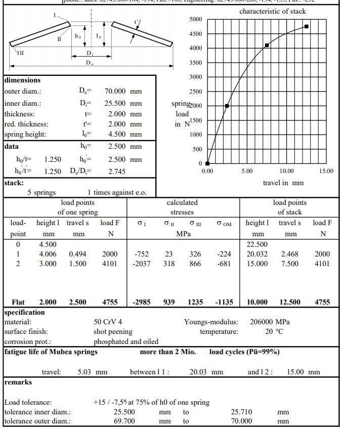
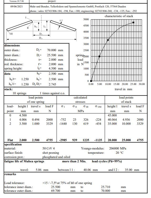
The Bellevilles are 70mm OD, 25.5mm ID, 2mm wall, 4.5mm height Qty – 5. That gives a height of 22.5mm.
At 2000N preload, they are compressed to 20mm ( lower half of image below)
At 4200N they are compressed to 15mm ( upper image half ) with a 5mm extend., ie , a 68% crush.
Use of odd numbers of Belleville spring is OK, if always in series, ie, each one inverted in relation to its mate – if you nest them, they can still be odd numbered, but each must have a nested mate…
Clearances have been adjusted all round to eliminate over-constrained contact.
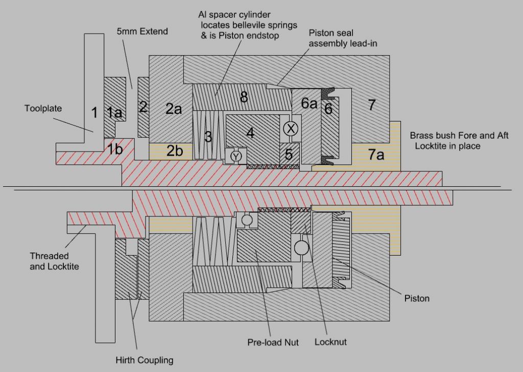
A much larger diameter thrust bearing fitted behind the piston to prevent canting. Piston also impinges on spacer -8- when pressurised, as end limit stop.
The pre-load nut -4- now has a lock nut -5-.
Assembly and operation ( as I see it..)
Toolplate -1- and shaft -1b- are threaded and locktite bonded. Hirth coupler -1a- is then fitted to -1- : it centers snugly on shaft -1b-.
Face -2a- is bolted to housing -7-, then brass bush -2b- and -7a- are locktite'ed in place, using shaft -1b- as alignment guide.
A lathe cutting tool is fitted into the toolplate.
Shaft assy -1,1a,1b- is extracted and Hirth coupling 2 is mated with mate -1a-. Housing -7- then fitted to lathe cross slide, locktite applied to Hirth -2- to housing -2a- face and the shaft assy inserted into the bushes.
The cutting tool is aligned with lathe center height, and the shaft assy slid to mate -2- to -2a- and kept in place till locktite cures. Shaft assy removed, then holes drilled and tapped into -2a- to bolt down Hirth -2- to housing -2a-.
-2a- unbolted from main housing.
Shaft re-inserted, Bellevilles fitted, thrust bearing Y fitted, and lock nut 4 tightened till Bellevilles are compressed to 20mm. Locknut fitted -5-. Piston assy -6a / 6- fitted into housing -7-. Cylindrical spacer -8- fitted in housing -7-.
Thrust bearing X fitted over locknut -5-.
Assy -1,1a,1b- , -2,2a- , -3- , -4,5- and thrust beearings are now slipped into the housing -7-, into bush -7a-.
-2a- then bolted onto housing -7-..
ETC….
Seems such a waste of time, removing all that solid material from the innards of housing -7-, and then refilling it with odd shaped pieces of material again…
Joe
10 June 2021 at 00:05 #549104Ross 77
Participant@ross77Hi Joe
That all makes sense. You have used bigger Bellevilles then we did and looks like you have a larger piston diameter to deal will the forces required to open the Hirth coupling.
We were limited in cylinder size and a max 8 bar, as safe usable, pressure so I had to balance to pre-load force and the opening force. I'm sure you are aware but by using more springs you can change the load profile and reduce the opening force.
There is the down side that the stack is bigger but if you are considering long term reliability then it might be a good trade off as it will give the thrust bearings and stepper motor an easier life.
for example if you doubled the stack to 10 springs then your 2000N preload is at 5mm and the open stack force would be 3300N @ 10mm. That is nearly 1000N (25%) lower then 4200N from a 5 stack system.
It might not be so critical here but I have done this on my mill PBD to keep the max loads as low as possible for reliability.
5 Stack loadings
10 stack loadings
10 June 2021 at 08:34 #549110Joseph Noci 1
Participant@josephnoci1Thanks Ross.
Not sure what diameter your piston is – mine is 90mm, with 24mm lost in the center bush area, so around 9 square inches which @ 120psi is around 4800N – to mix a few units…
I have no idea how to integrate losses, friction, etc into this, but I am content to go to 120 psi (8.2bar).
I played around extensively with the evaluation tool you linked to – the one you used to create the data sets in your post above. I would have liked to go for 8 springs, maybe more, but the housing length becomes an issue for me to machine – I would really like to machine the housing interior in the lathe with the 4Jaw, rather than on my small mill with the boring head – that is excruciating in focus and concentration, and very slow to get the pneumatic seal finish required..
A lengthened housing in the 4jaw scares me though – the housing is quite large – 140x130x95mm deep -5 more springs adds another 15mm or so to the depth- we will see – need to model a bit more!
I have reduced the Hirth engagement to 4mm, expecting a 4.5 to 5mm extend for the teeth to clear. I kept the tooth angle at 60deg – steeper would allow reduction of preload forces as you say, but I worry as to how steep – when does it become a 'taper-lock' with corresponding big force needed to break the lock?
When you say 8bar is 'safe useable' – what do you mean? I have a 2KW 2 cylinder compressor that seems very comfortable at 10bar. The pneumatic solenoids I have (Festo) for air control give limiting pressures of 15bar. Am I missing something here?
Joe
Edited By Joseph Noci 1 on 10/06/2021 08:36:11
11 June 2021 at 00:46 #549245Ross 77
Participant@ross77I guess that's the joy of engineering and there's always a balance between design and buildability.
To reduce the machining and wasted material could you use a thick wall box section for the main body and then just machine up a rear plate for the piston bore? I considered using an old hydraulic cylinder but worked out to expensive in that ID.
I'm not sure on the taper lock, its quite a large diameter and small contact area compared to a morse taper tool. I guess there will be a point at which it could lock up.
The 8 bar safe usable was due to the recharge range and ensuring there was always sufficient pressure. Whilst they will pump up to 10 bar they then drop to 8 bar (or less) before recharging. TB is using a small silent compressor and had to adjust the lower limit to get it to work.
11 June 2021 at 07:50 #549262Joseph Noci 1
Participant@josephnoci1Thanks again for your ideas and input. Will spend a bit more time and effort modelling different approaches before committing to cutting I think. The concept is OK but machining capability is a real constraint.
Thank you.
Joe
19 June 2021 at 21:36 #550494Joseph Noci 1
Participant@josephnoci1Further progress in the CNC Lathe – New Spindle
As mentioned before, the current headstock/spindle arrangement , although good for rigidity with zero collet chuck overhang, is a problem for the tool changer – boring bars and drills with crash with the headstock when turning conventionally.
So I decided to remake the main spindle, with a backplate to fit a small 4inch 5C collet chuck. The ATC tool plate is now designed to have the long axial tool clear the chuck diameter.
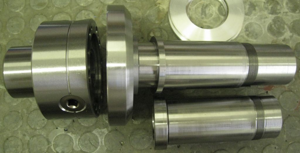
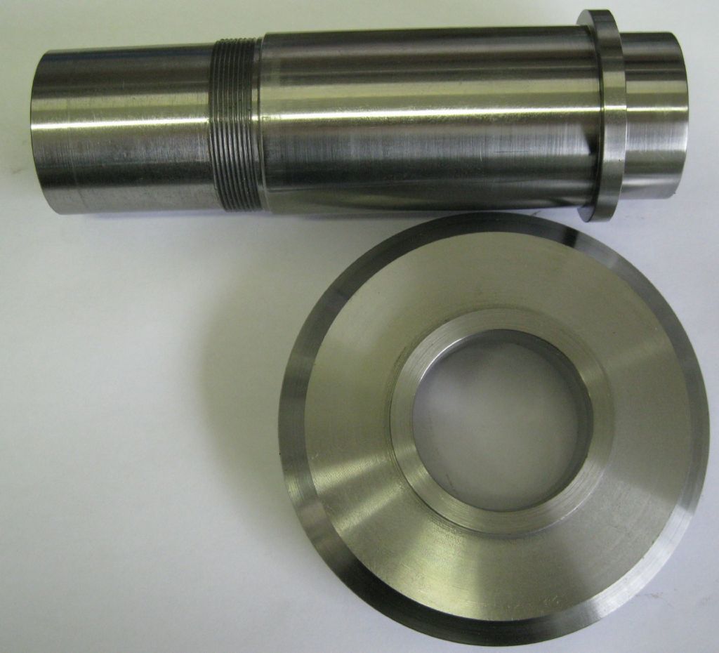
The spindle at bottom is the old short one. The backplate is seen not yet fitted.
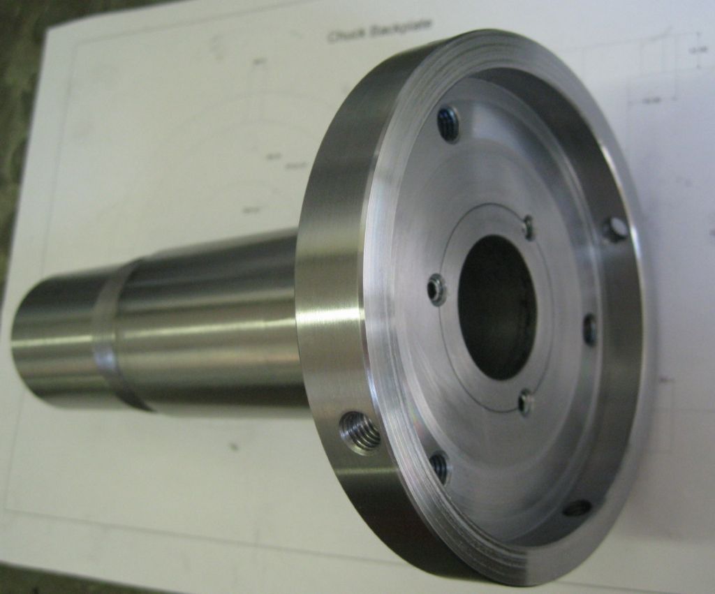
Backplate below, before drilling and fitting to spindle.
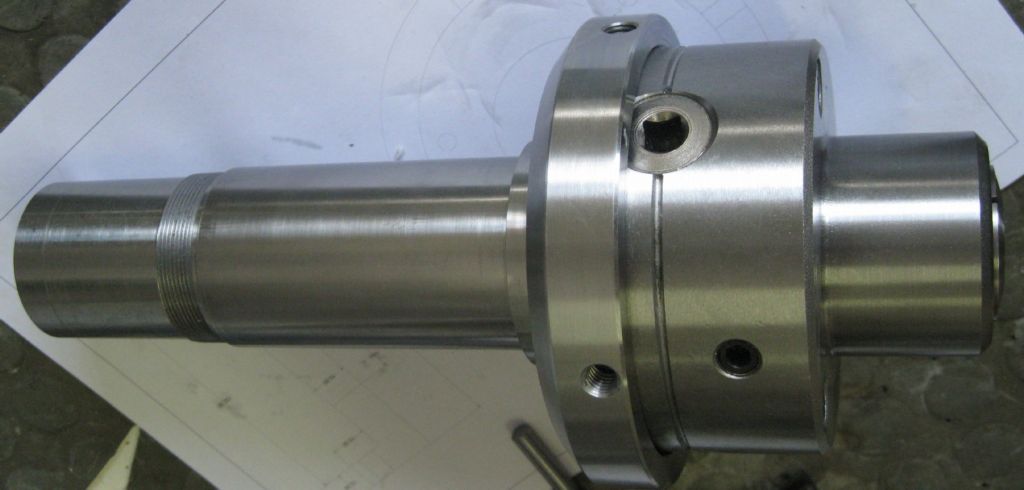
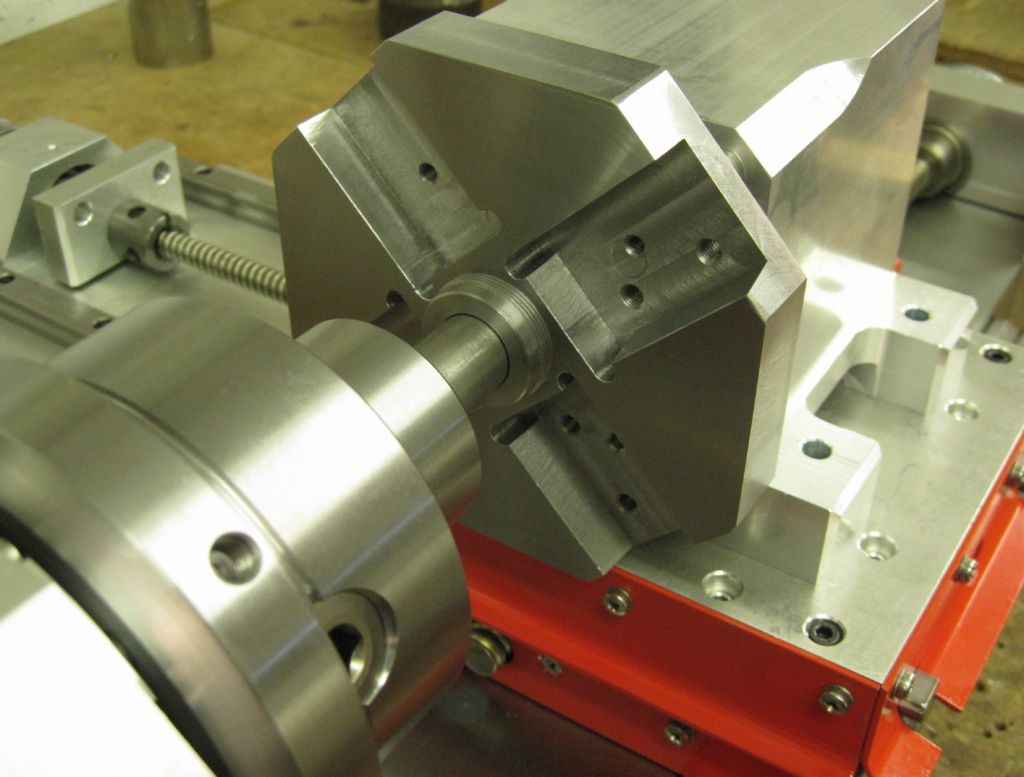
Backplate drilled , tapped and fitted to spindle. The 4 peripheral M8 holes are for grub screws to adjust the 5C chuck to run true when required. The 3 holes between spindle and backplate are to lock the backplate in place, with 3x M6 grubscrews, and locktite on the spindle/backplate interface and grubscrews.
The 5C chuck – BISON
Spindle assembly done.
Headstock assembled – backplate runout axially and radially is around 0.008 max – will true it up on the lathe itself.
19 June 2021 at 21:46 #550496Joseph Noci 1
Participant@josephnoci1Now that the new spindle is 'done', I get to continue with the Toolchanger.
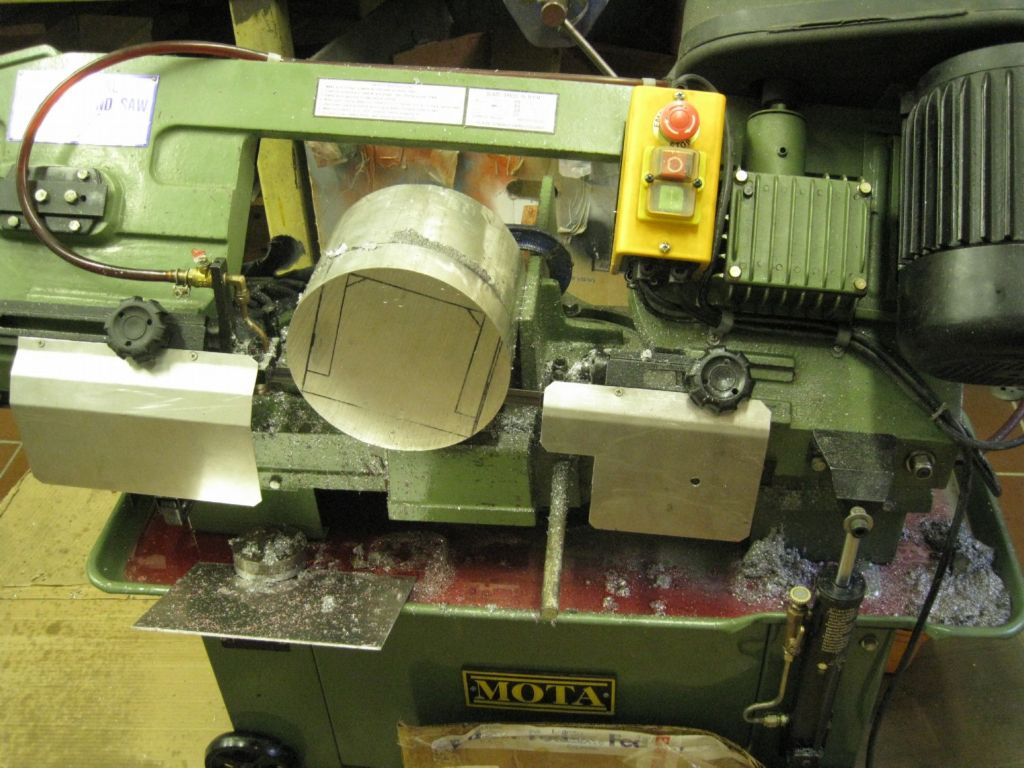
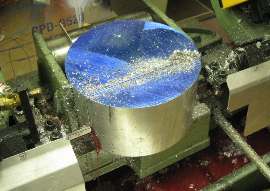
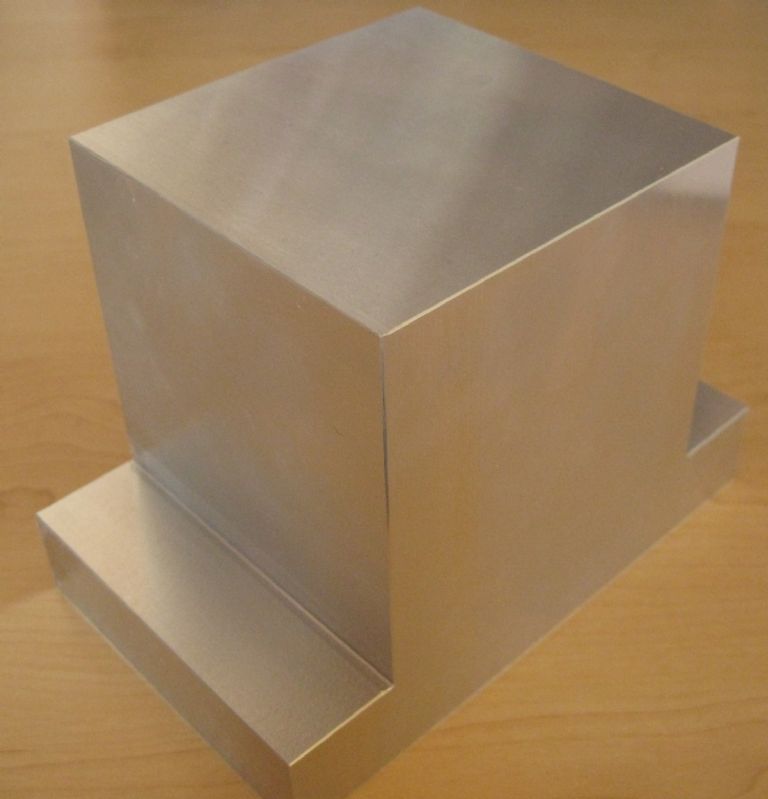
As usual, materials are a problem for me – I needed a big block of aluminium for the toolchanger main body – the body is 120mmx110mmx100mm deep, with mounting feet protruding 30mm either side at the base. The only material I could get was a 200mm diameter x 140mm slice of Aluminium bar!
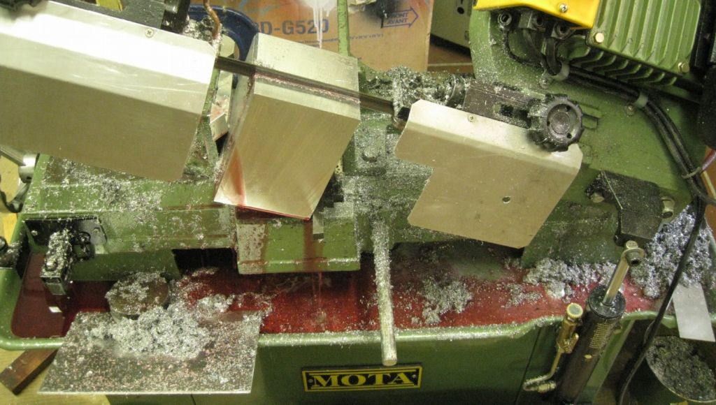
So, into the bandsaw for the better part of the morning…
First 40mm of the length…
Then the base…
And so on…
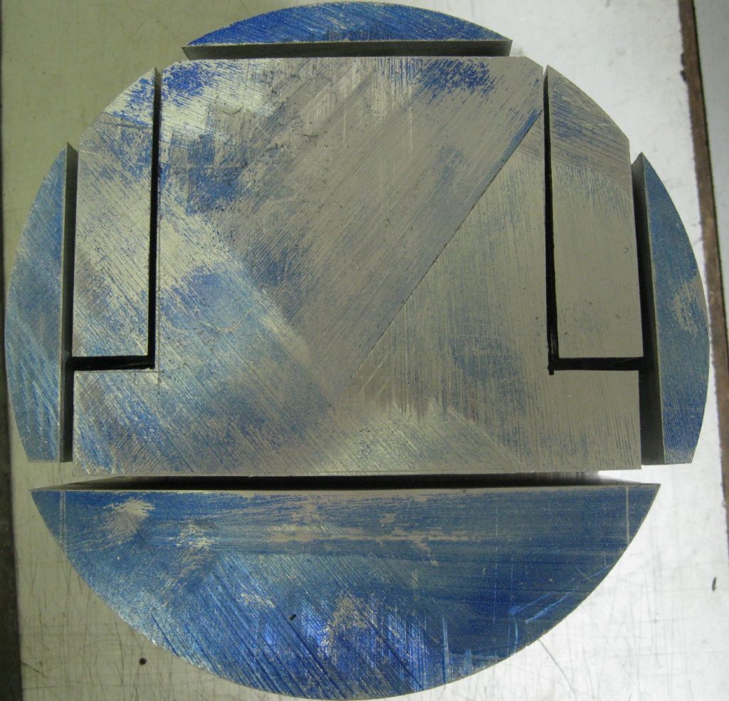
Leaving the puzzle…
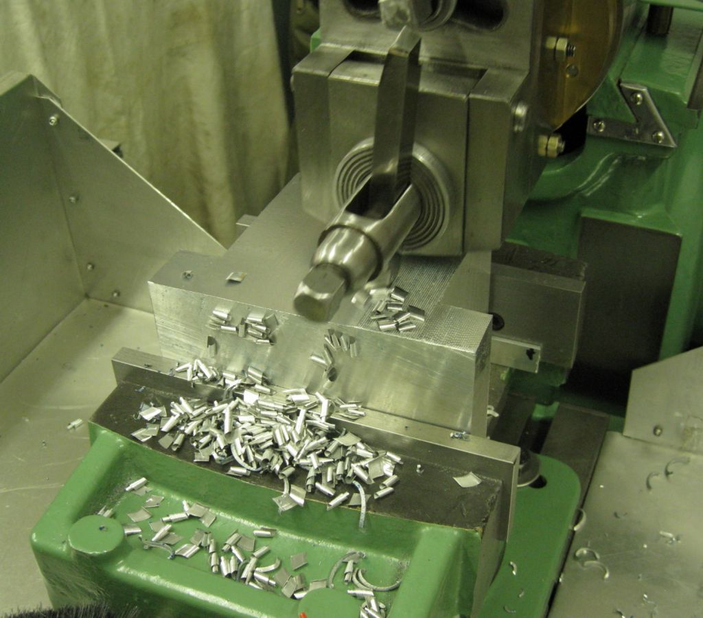
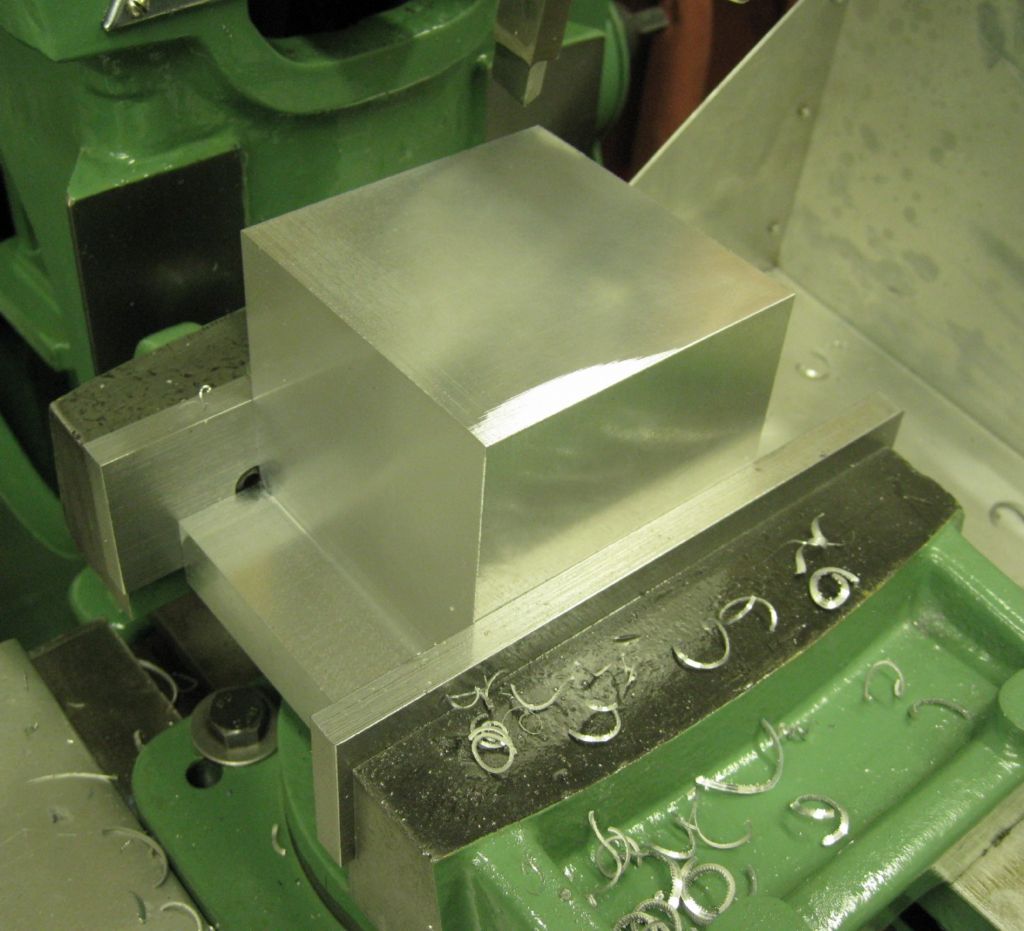
I cut around 3mm oversize as the saw does not cut that straight when abused this way..and so into the shaper to get the block to final size.
The Final Cut to do…
Next I have to bore out a 90mm diameter hole, 90mm deep in the one side….Hopefully in the lathe with the 4 jaw.
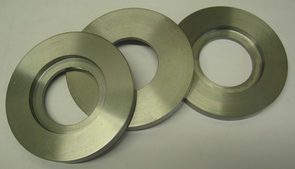
Also machined the blanks for the Hirth coupling – made 3 as I will probably mess one up..These are 100mm OD , 10mm thick EN3
Joe
Edited By Joseph Noci 1 on 19/06/2021 21:50:50
26 June 2021 at 21:00 #551506Joseph Noci 1
Participant@josephnoci1Progress on the Tool Changer main body machining.
There was still some considerable bandsaw work after cutting the main body block from that 'round bar'. This led to some modifications on the bandsaw…
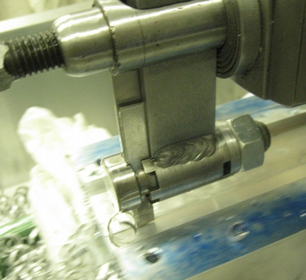
The saw has a coolant pump which is filled with a Rocol neat cutting oil – the red stuff seen in the pics of the cutting process. It works, but is real messy – sort of sticky and hard to get of the cut parts by simply wiping. Also, the saw's drainage system is abysmal! there is a sieved hole located in the center of the saw tray, and the tray is flat and the coolant pools everywhere on the tray except at the drain hole..So I made a new hole rear left, and raised the saw above its front wheels, forcing the coolant to run to the rear. I also raised the saw slightly from its right side wheels to force the runoff to the left as well. That now works well. Had to fit some plumbing to take that drain back into the tank. Then while I was making a mess, I replaced the Rocol oil with soluble cutting oil. And that was a big surprise!
With the Rocol oil, cutting a 140 x 100 piece of aluminium took 16 minutes ( 8TPI blade). With Soluble oil it took 11 minutes!
A tip for bandsaw users – cut a 40mm square of 10 or 12mm thick rubber – the canvas re-enforced stuff ( conveyor belting) . Then with a hacksaw cut a slit 2/3 down the center. slip that over the blade at the lower guide and it stops all the swarf from going into the drive wheels, and places where it's hard to clean out..
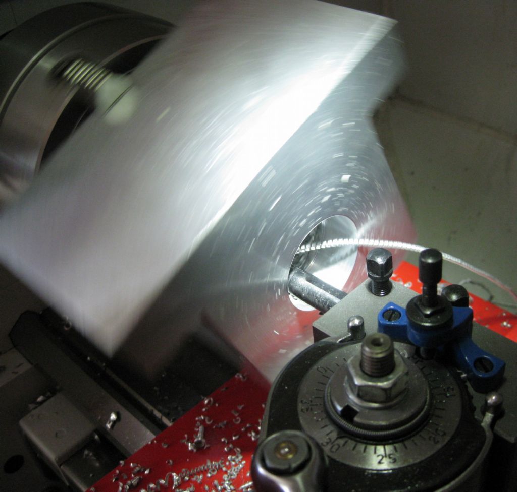
The onto the ATC main body machining – this was done in the 4-Jaw and was a little daunting. The chuck is 200mm OD. The block is 110x110x130 with 2 'ears' ( mounting feet) protruding 30mm from the base end.
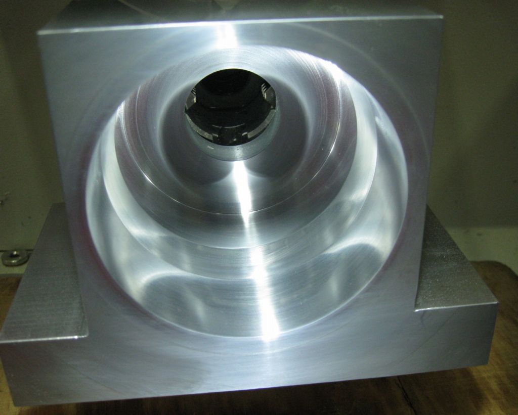
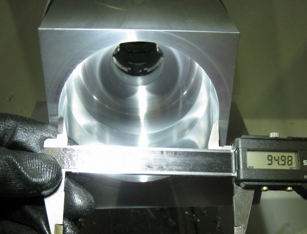
I could not swing it faster than 380-400rpm without the lathe starting to shake..The hole bored is all of 90mm deep, 95mm OD at the mouth with a tapered section as lead in for a pneumatic seal, then reducing to a 90mm hole.
The bore completed.
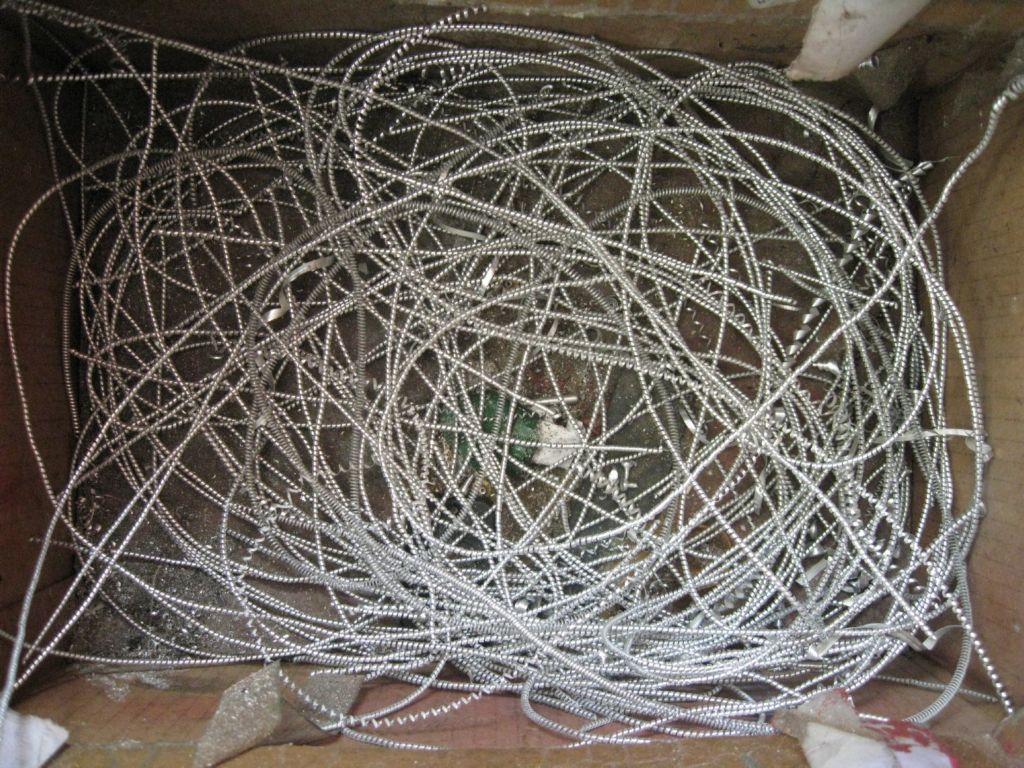
As the inner diameter grew, the surface speed approached what it should be for my DOC and feed rate, and these long snakes came off ( rather than the initial ugly stringy stuff..) Some of these are nearly 4 meters long! The snake would start and go down tween the lathe bed, out the bottom and down towards the floor, and every now and then one would lathe onto my socks and start twitching and wrapping around my ankle, while I am concentrating on stopping the autofeed just in time…
Now busy with the ATC main shaft, preload nut, pneumatic piston, bushes, etc, etc..
And trying to get up the courage to CNC mill the Hirth coupler…Maybe I will do one in PVC to see how it works.
Joe
30 June 2021 at 18:51 #552009Joseph Noci 1
Participant@josephnoci1The ATC is progressing well – Most major mechanical parts are done – awaiting the Bellville springs from South Africa still, and the toolplate has still to be contemplated..Then still the position encoder and stepper/stepper drive.
A refresher of the ATC innards:
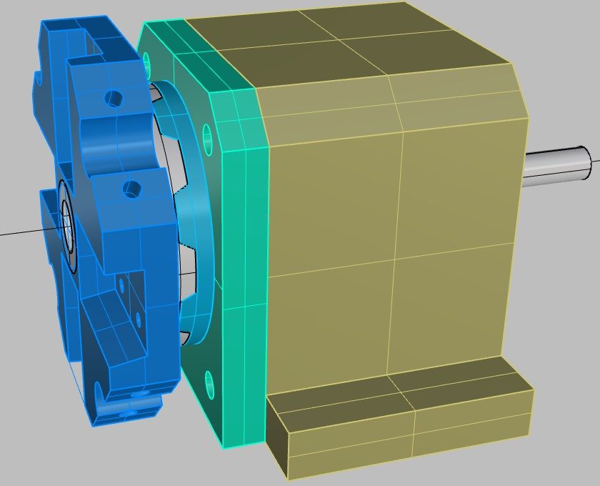
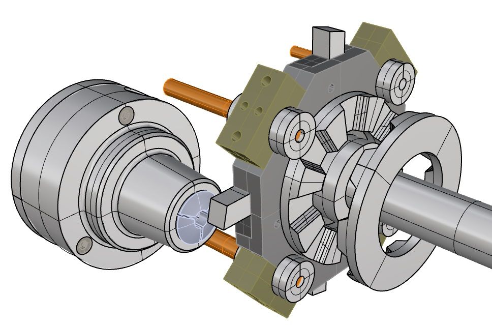
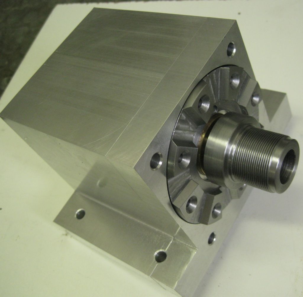
Front view of main Housing with fixed Hirth Coupler (item 2) visible. Threaded main shaft fits to tool plate ( Item 1)
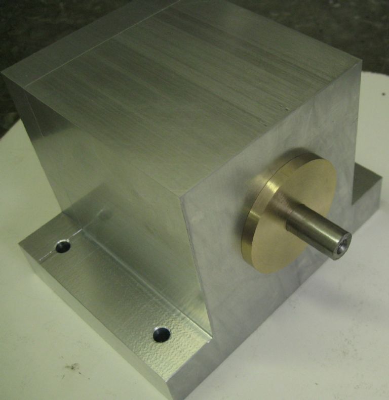
Rear of Main Housing with rear Brass bush (item 7a) amd main shaft (item 1b)
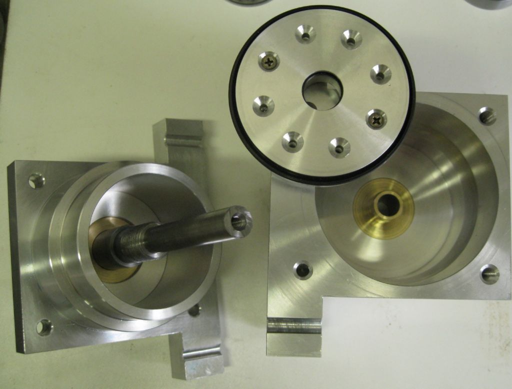
Housing Assembly interior –
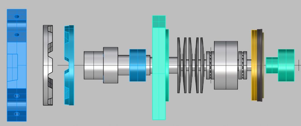
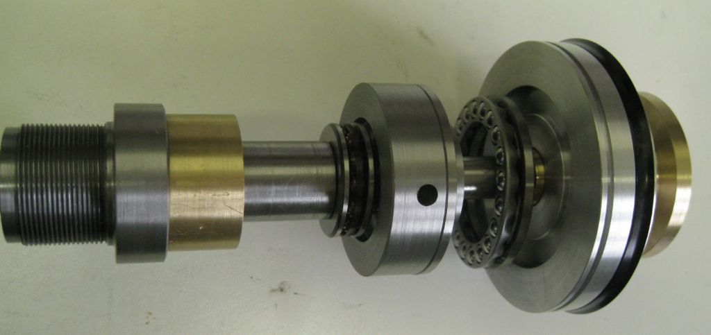
Main Shaft assembly with front and rear brass bushes, pre-load and lock nuts ( items 4 and 5) , pneumatic piston, seals and seal retainer ( items 6 and 6a).
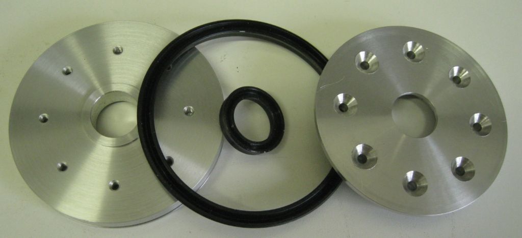
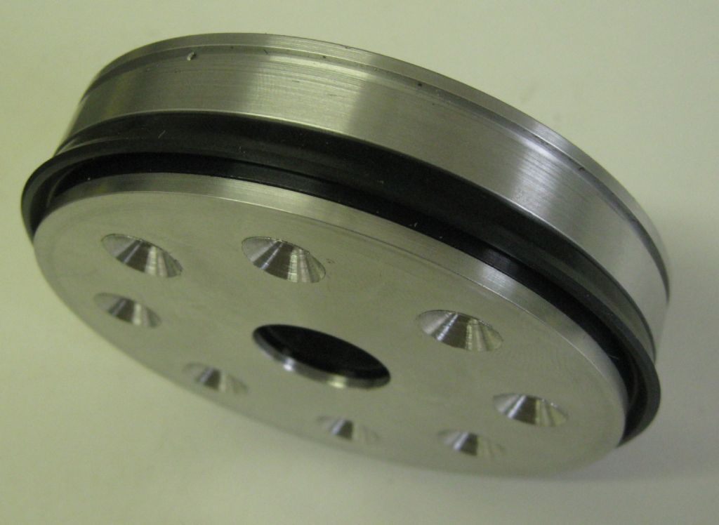
Breakdown of piston assembly – left main piston (item 6a) middle the outer and inner seals, right the seal retainer.
Piston assembly together – rear 'O' ring not yet fitted in groove
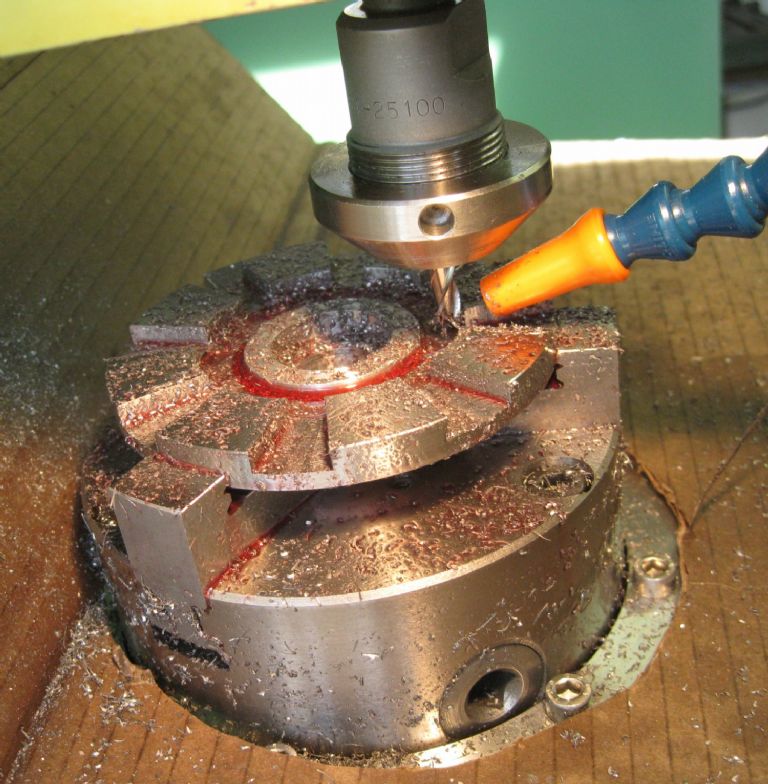
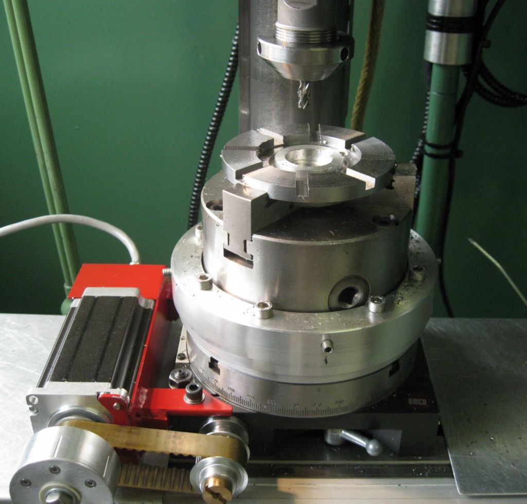
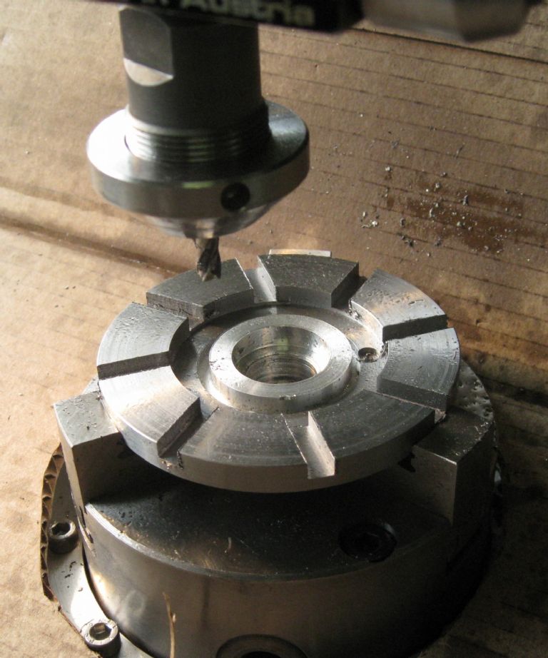
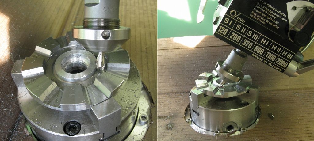
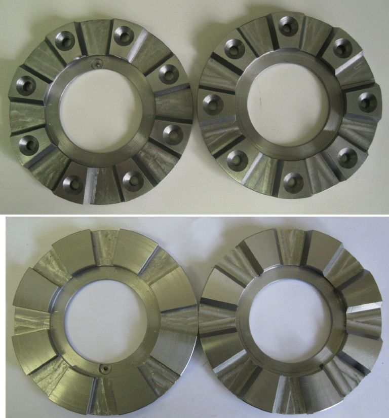
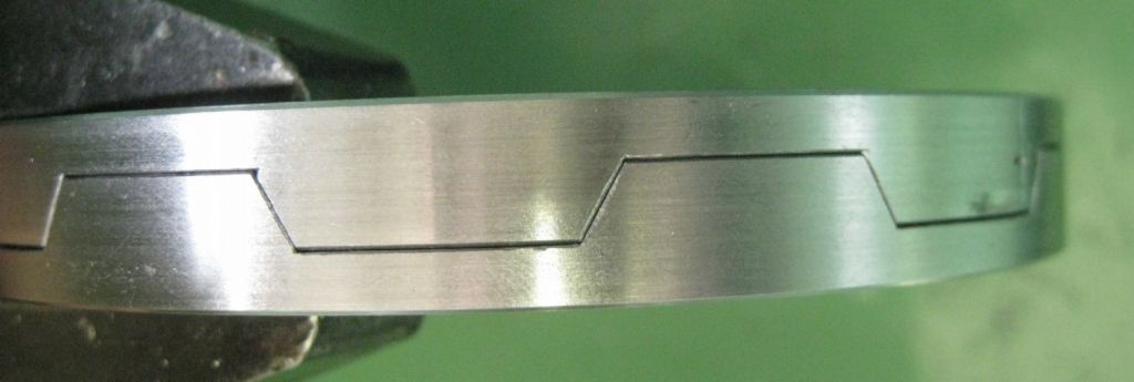
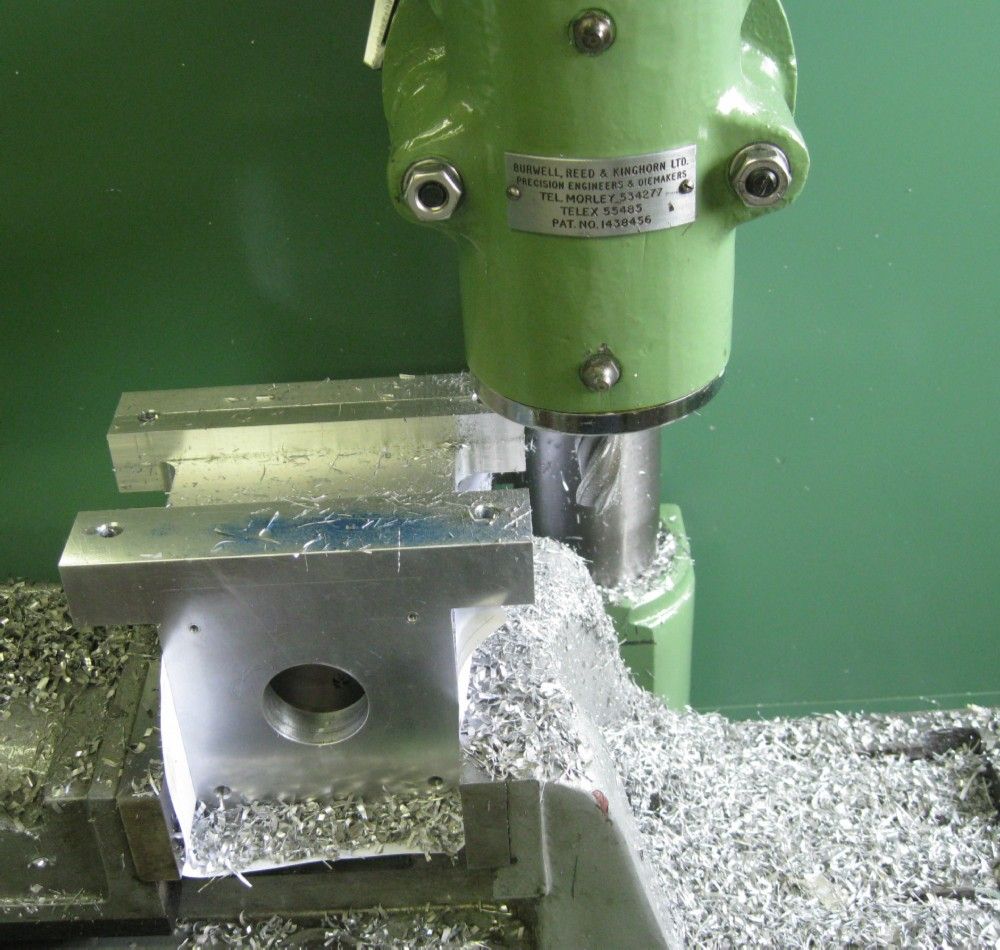
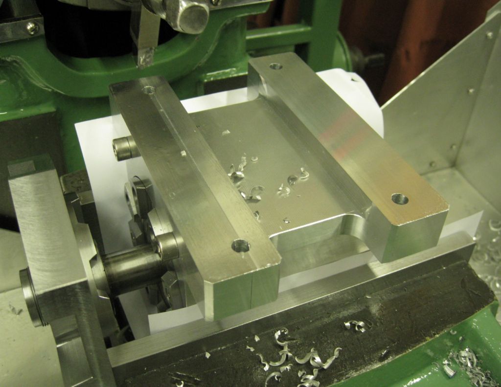
The Hirth Coupler milling operation was complex – many angles and offsets to be implemented accurately. I decided to tilt the mill head to the 30deg angle on the Hirth wedges, rather than make a special milling cutter. However, that required complicated juggling of mill cutter edge positions and offsets, with much head scratching and reversion to CAD.. In the end it was remarkably successful!
Roughing out the slots:
The cutting the 30deg angles to the sides of the slots:
The results:
And the fit – not too shabby-
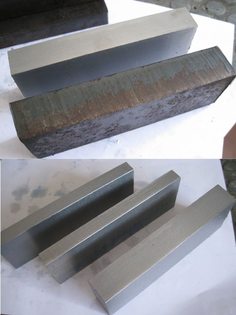
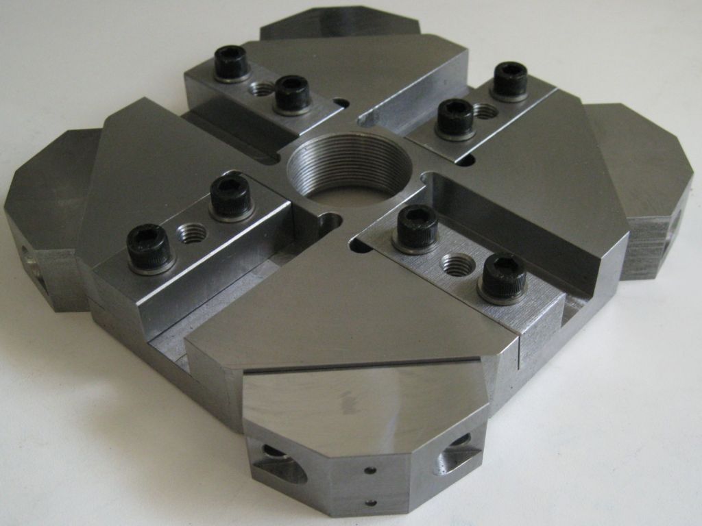
The flat plate I needed for the Tool holding wedges in the toolplate, as well as the clamps for the peripheral tooling on the toolplate ( drills, boring bars, etc) was hidden in some really rough, rusted flame cut steel plate – from a local ship-yard…
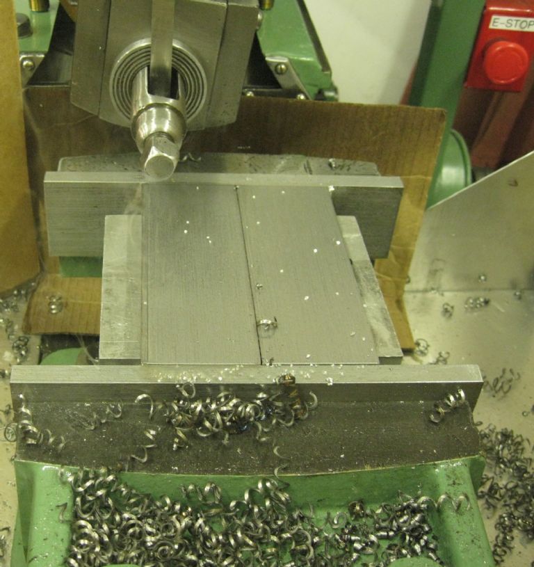
Extracted from the rusted plate by means of the shaper…
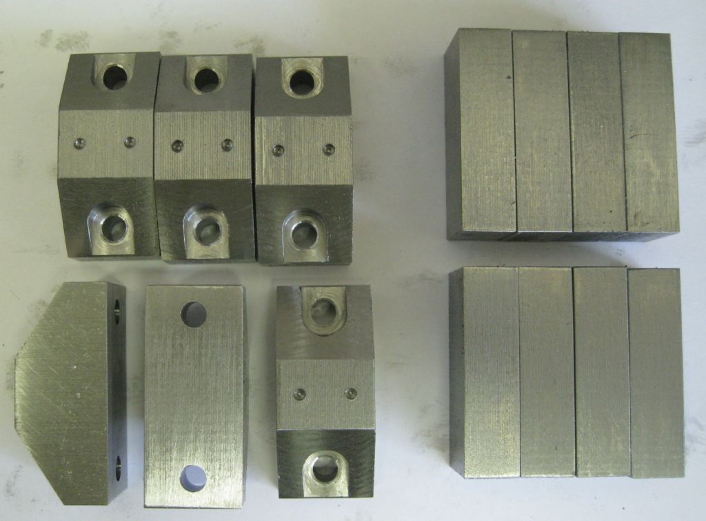
Giving the wedges and clamps:
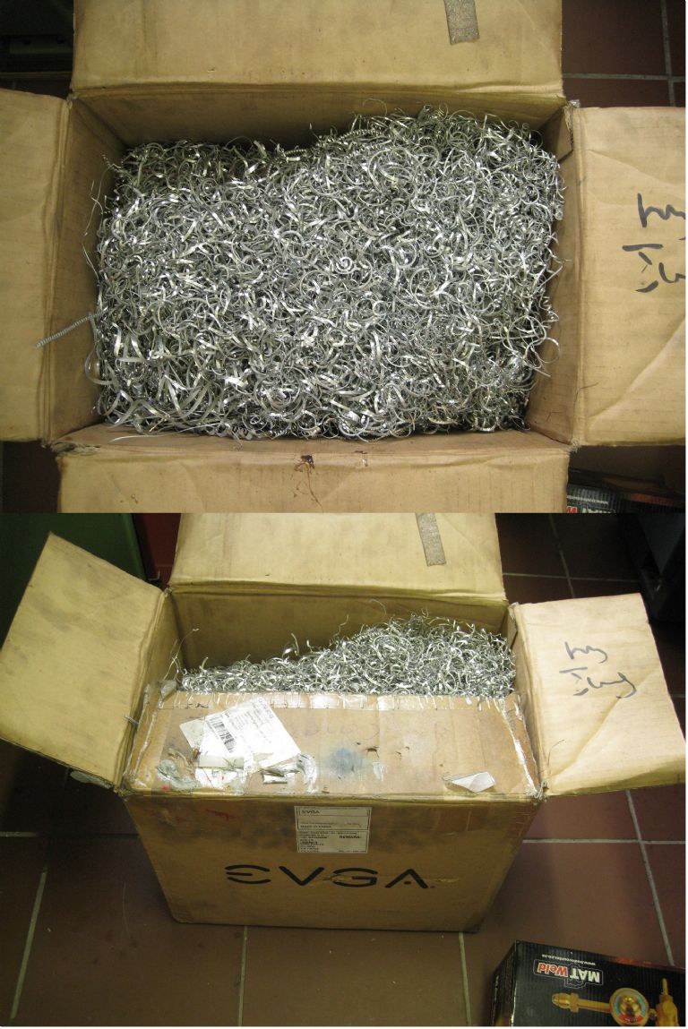
And the whole thing so far filled two cardboard boxes of 450mmx400mmx350mm, one with Aluminium and one with steel swarf..
Hope I have not bored to many folk…
On with the tool plate now..
Joe
1 July 2021 at 14:13 #552090Andrew Evans
Participant@andrewevans67134This looks amazing work Joe – well done!
1 July 2021 at 14:23 #552092 Ady1Participant@ady1
wow, what a great thread
4 July 2021 at 20:29 #552615Joseph Noci 1
Participant@josephnoci1Ady1/Andrew, thank for the encouragement.. This is turning out to be rather overwhelming..
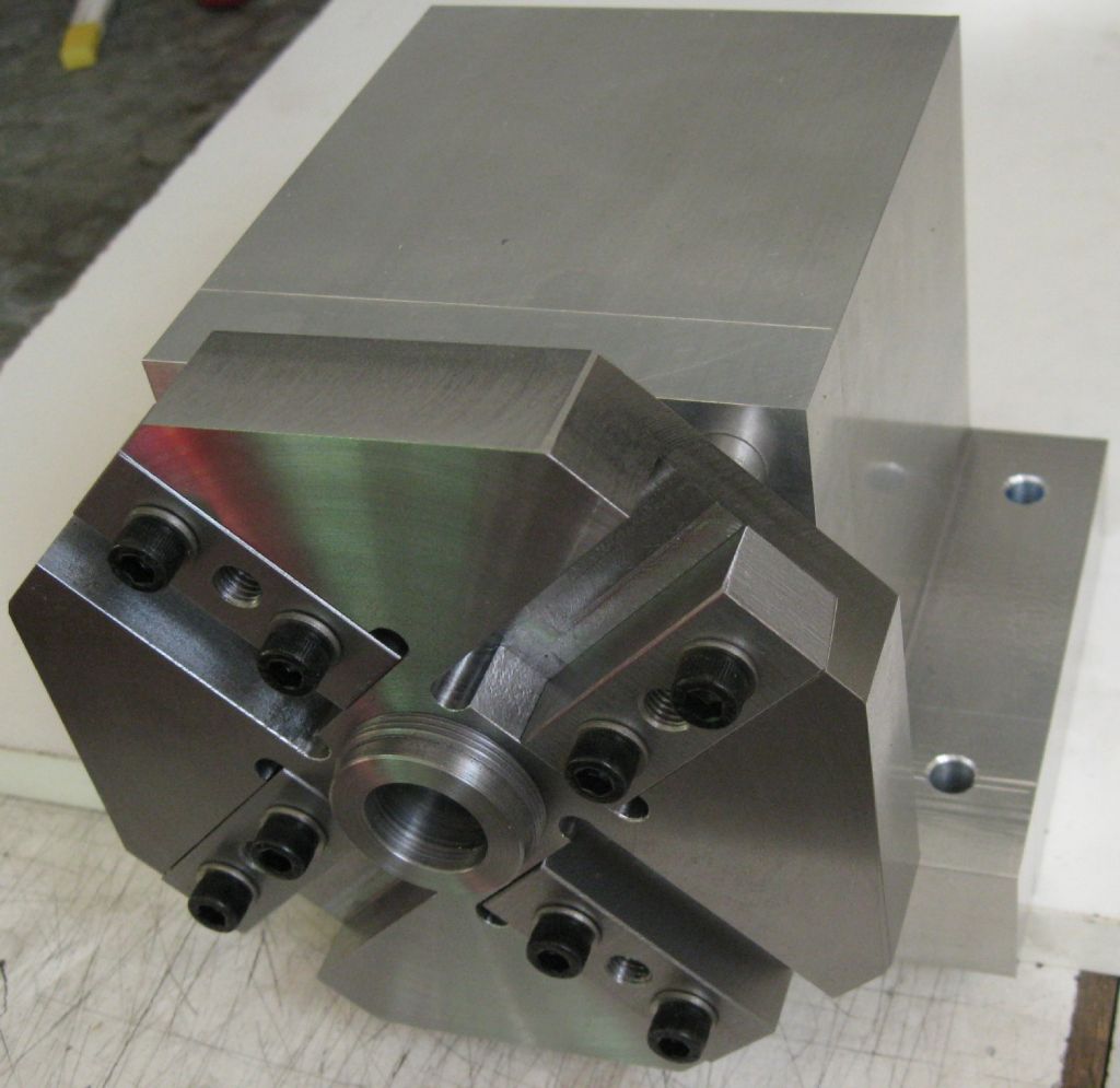
I have progressed well on the toolplate.
A slice of 150OD x 30mm thick steel from a MASSIVE hydraulic ram that had bent…(!) was the raw stock. This was faced both sides down to 23mm thick, and then lots of milling.
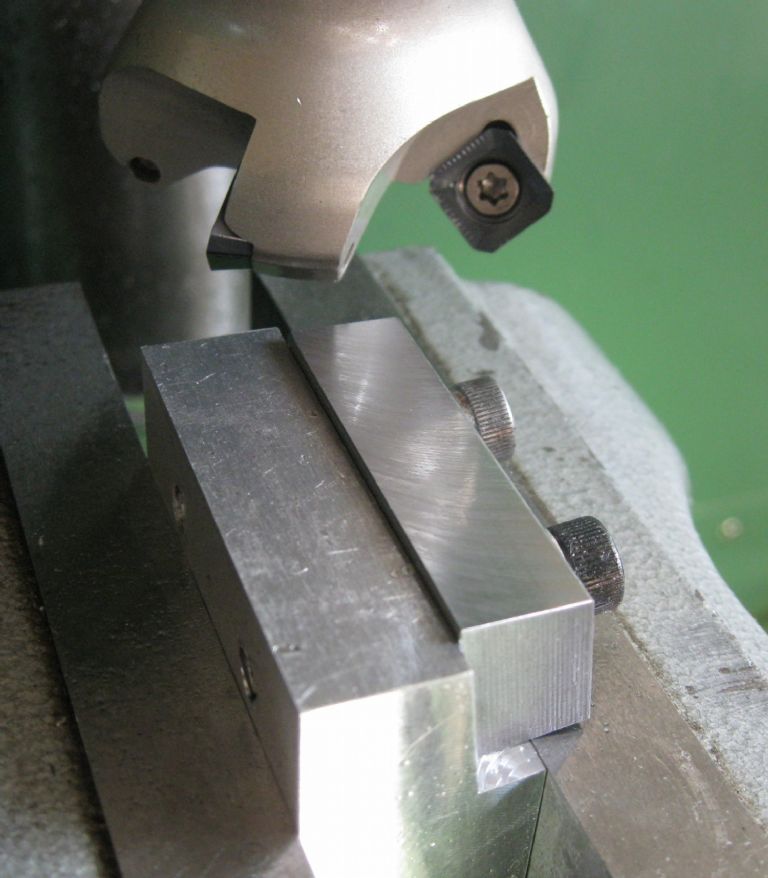
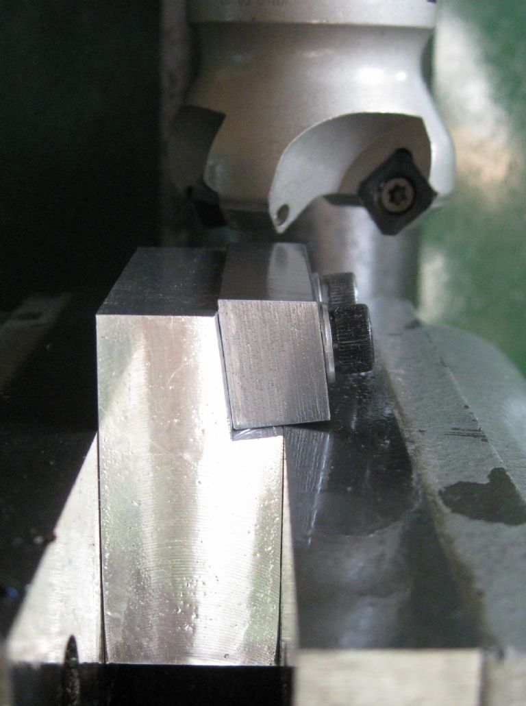
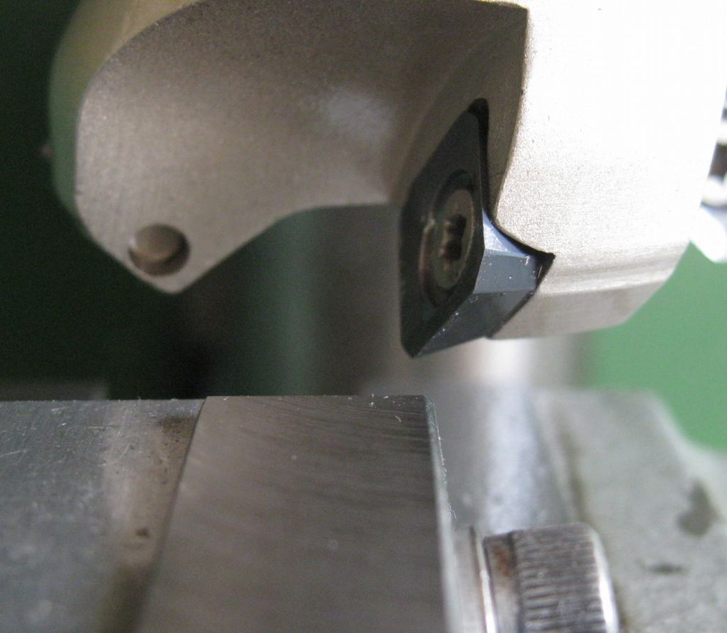
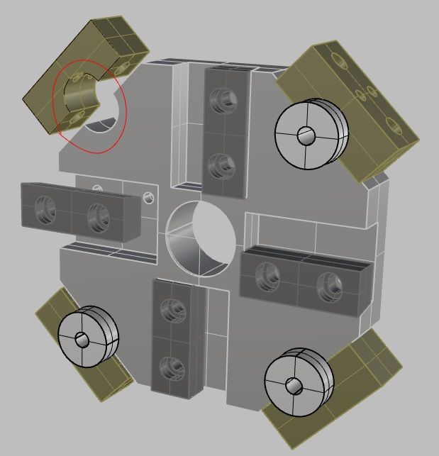
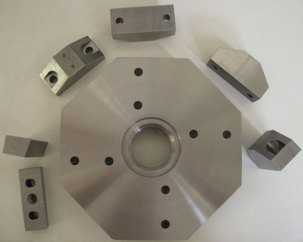
The cutting Tool wedges were previously roughed to dimension on the shaper. An angle jig was made up to hold each wedge in the mill vice to cut the pressure angle as is in the toolplate itself. A 4-insert carbide mill cutter was used to cut the angle. The cutter has a very high rake angle and very sharp carbide tips and cuts the steel beautifully, leaving a gleaming mirror finish.
Closeup of the cutter tips and Rake angle
Holes still required in the tooplate are the holes for the axial tools, as circled in red in the rendering below the toolplate image under. Those holes will be done in situ once the toolchanger is fitted to the lathe and the cutting centers determined. This will ensure the tools end up on lathe spindle axis.
Also, the holes threading on the rear of the toolpate for the toolpate Hirth coupler.
The hole for the axial tooling circled in red below
Toolplate rear view.
Now to get the new spindle/headstock assy aligned on the lathe. Once done, I can trial fit the ATC and trim the body base under to get the ATC spindle axis aligned with the lathe spindle axis. Then fix the ATC in place and drill a and bore out the axil tooling holes in situ.
And find more cardboard boxes for the swarf..
Joe
6 July 2021 at 22:36 #552957Ross 77
Participant@ross77Really nice to see this come together and how you have approached it in a different way to how we did. The results are amazing and I cant wait to see it in action.
The Hirth coupling looks good. The math for tilting the head stock must have been fun!
Have you thought about the motor and encoder set up yet?
9 July 2021 at 12:27 #553396Joseph Noci 1
Participant@josephnoci1Posted by Ross 77 on 06/07/2021 22:36:27:Really nice to see this come together and how you have approached it in a different way to how we did. The results are amazing and I cant wait to see it in action.
The Hirth coupling looks good. The math for tilting the head stock must have been fun!
Have you thought about the motor and encoder set up yet?
Thank You for your support! Yes, The motor/encoder is essentially done – The electronics for tool position detection is working well in prototype form and that is being 'industrialised' now.
So photos of the progress:
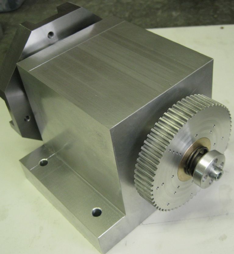
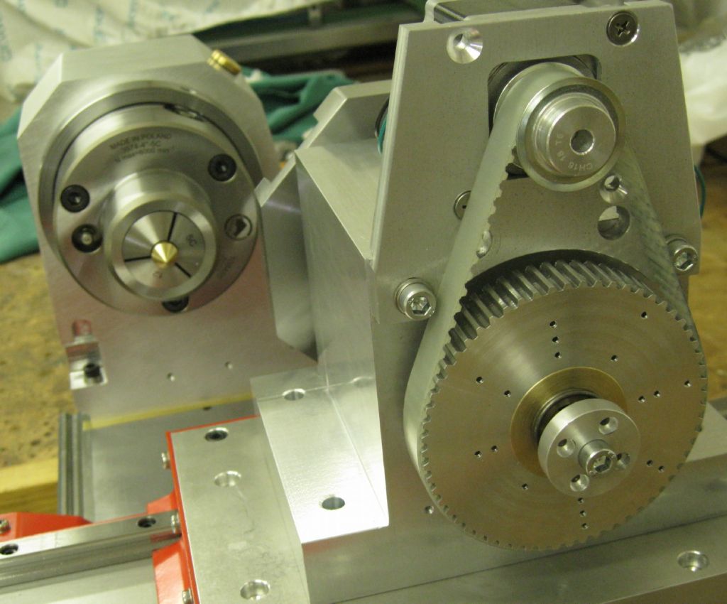
The drive motor is a NEMA 23 Stepper, with a 18 tooth pully driving the main shaft pulley of 60 teeth. At 800 steps/rev this gives a neat 333 step pulses per 45deg tool position selection.
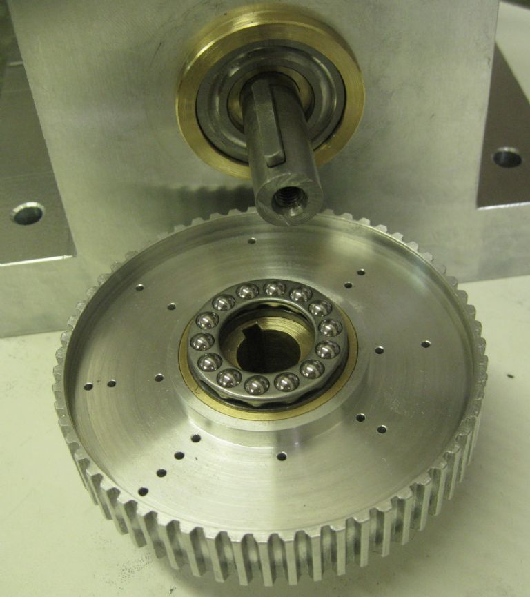
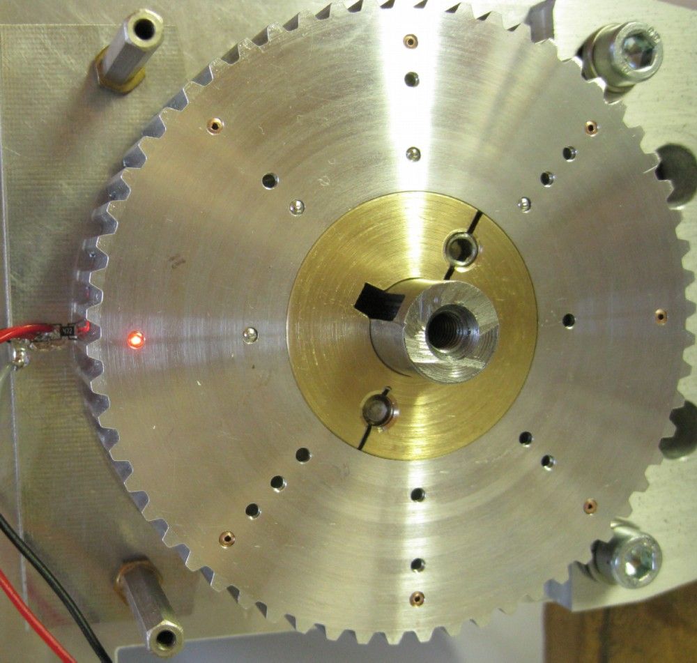
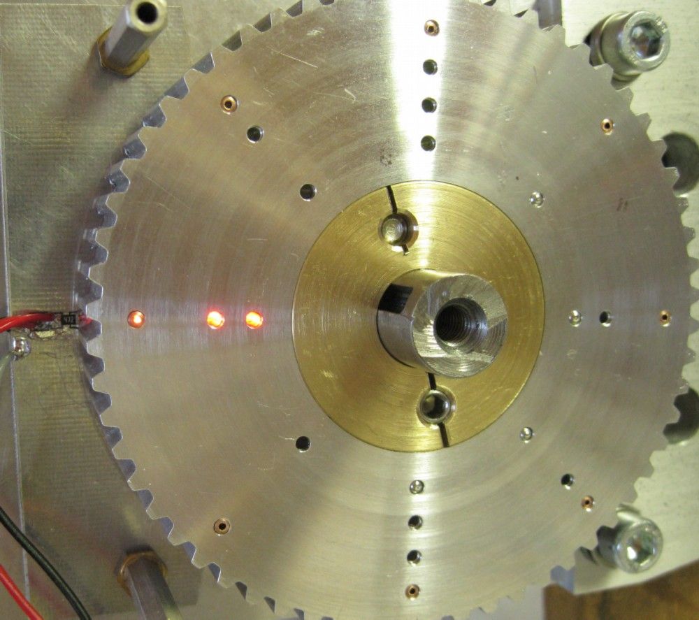
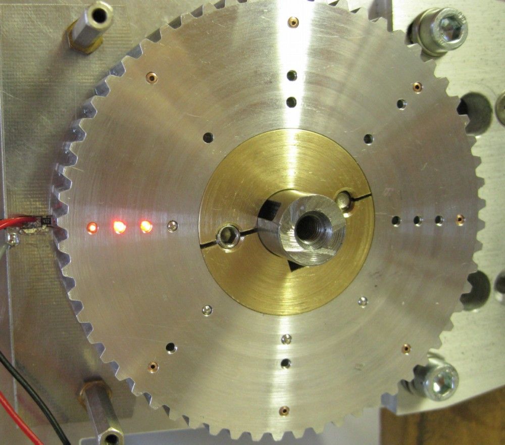
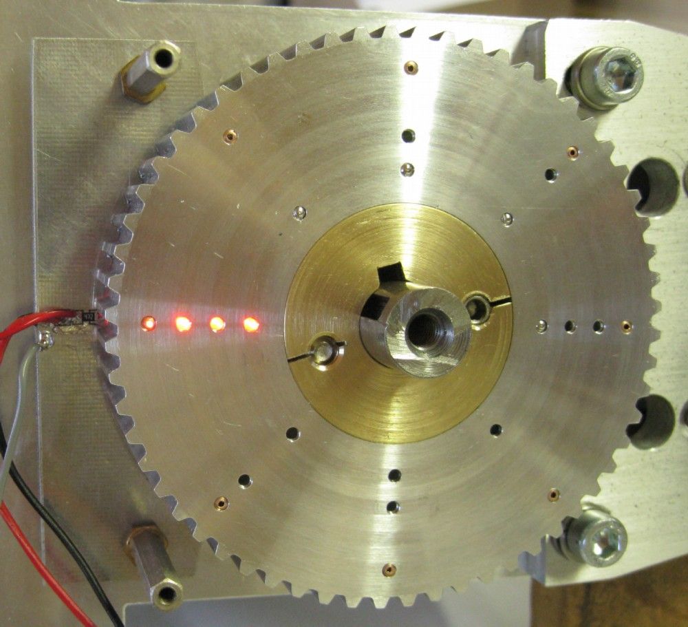
The tool positions are denoted by optical detectors, using a Binary code per position ( Gray is an overkill, and not easily recognized by eye without gymnastics..). The shaft drive pulley incorporates the encoding as seen below.
Reverse side of pully with thrust bearing and drive keyway. The pulley slide on the shaft as the pneumatics push the toolplate out 5mm to clear the Hirth couplers.
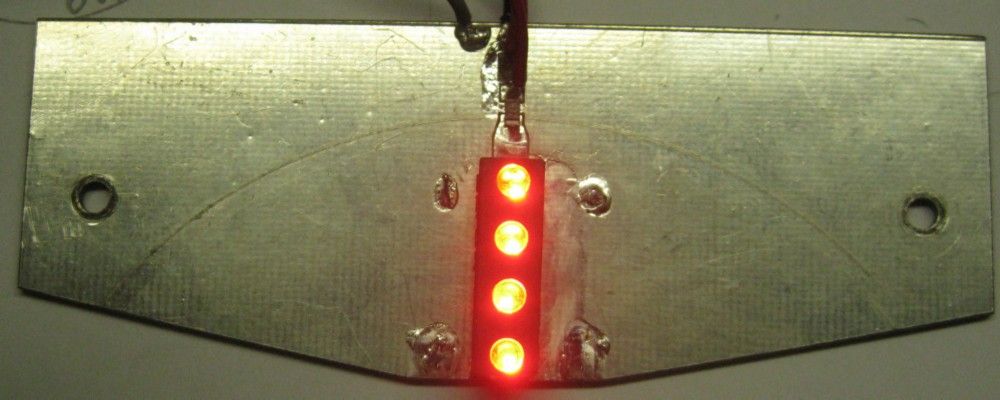
The LED Illuminator PCB – sits behind the encoder pulley lined up with the holes.
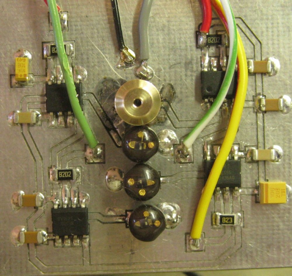
The photo transistor detector PCB prototype. This fits in front of the encoder pulley, over the illumination holes.
4 Transistors, with one ( upper one in photo below) in a brass cap to present a small optical orifice – see reason in explanation with following photos.
The encoding is in binary, 0-7 giving 8 tool positions. There is a 9th position, in the toolplate center, but that is available at any tool position selection and is differentiated by tool offsets only.
There are however 4 sets of holes in the encoder – the inner 3 are the binary encode and the outer is a tool position reference – whenever this detector is active, the other three binary detectors conditions are guaranteed valid. This reference detector is optically stopped down so that there is about 1.5 to 2 deg of movement withing which it is valid. The other detectors optical windows are larger and will detect position before the reference, and maintain position after the reference is declared invalid. This ensures there is never a false tool number for a selected position.
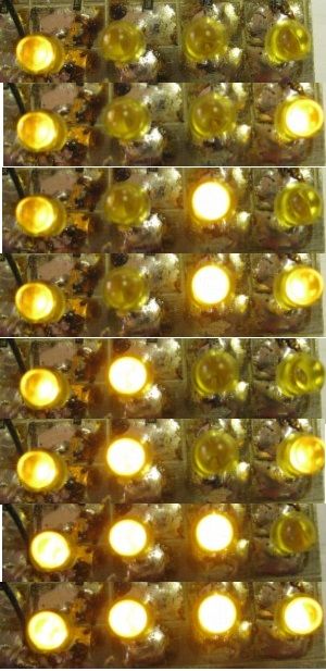
I knocked up a small PCB with 4 leds to be driven by the optical detectors so I could visually validate each position. I did verify that the detection signal is clean, with an oscilloscope – no oscillations, etc.
The photo-detector interfaces to a 555 Timer IC. I drive the internal voltage divider and the 555 is fed from +12v. The signal from the phototransistor must go below 4volts to activate the 555 output ( lit by illuminator LED) and then must go above 8volts to deactivate the 555 output. There is therefore a large hysteresis and no possibility of oscillation.
Binary code per tool position below – from 0 to 7, with the left hand LED showing the reference detector valid with each position. ( the right hand led – Bit-0, is not as clear as the others…camera position issue..)
Joe
Edited By Joseph Noci 1 on 09/07/2021 12:29:18
Edited By Joseph Noci 1 on 09/07/2021 12:37:51
9 July 2021 at 12:35 #553397Joseph Noci 1
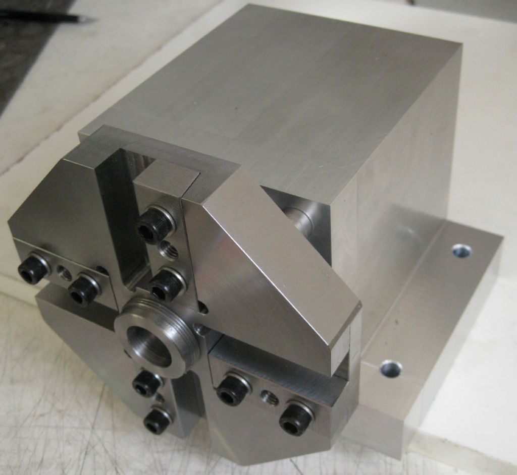
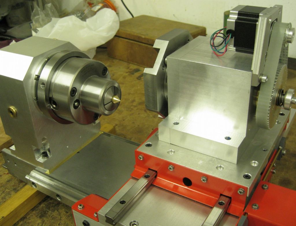
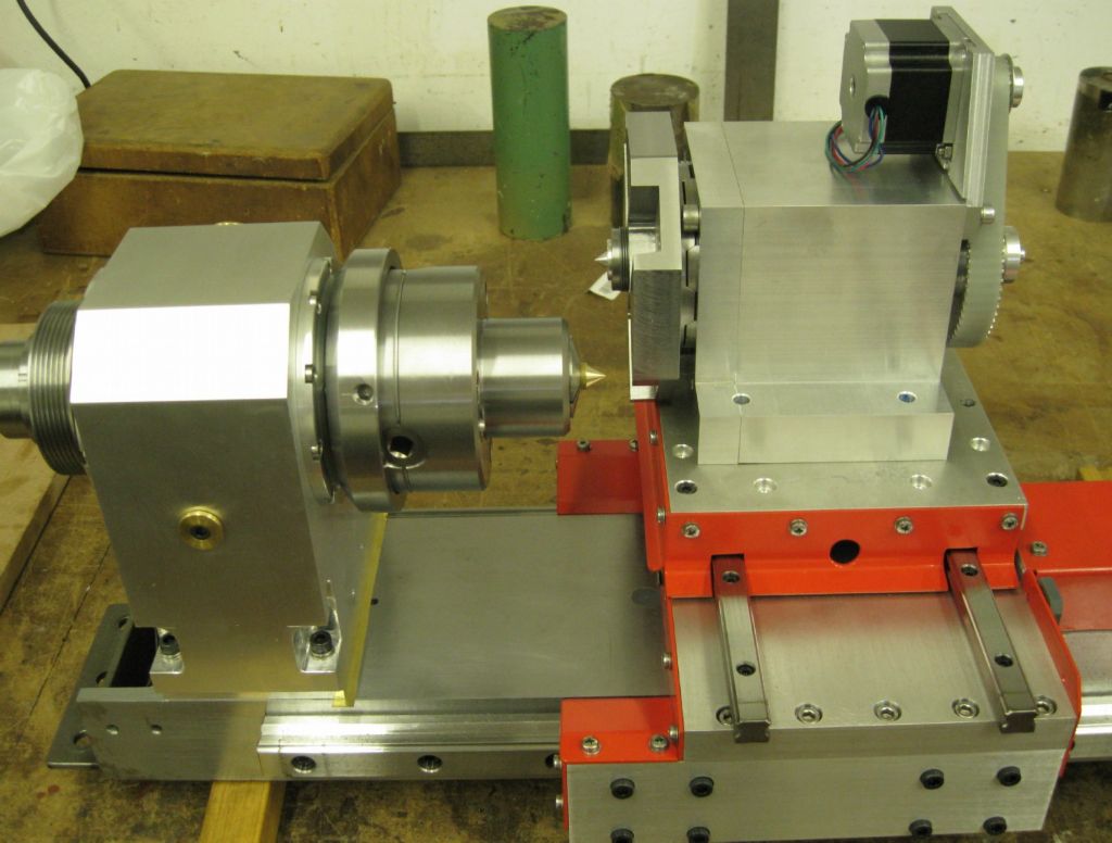
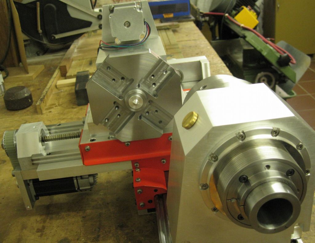
Participant@josephnoci1Some more photos – The ATC placed on the lathe to determine center height, etc..The ATC center is 1.75mm higher than Lathe spindle center – this was done on purpose, although the 1.75mm was not 'designed' in – the idea being that once it is all together I will invert the ATC body in the shaper and bring it to proper height. This was done so since it is awkward to determine beforehand precisely the buildup of tolerances over the months of build…
The stepper drive concept is seen here.
Joe
11 July 2021 at 16:39 #553709Joseph Noci 1
Participant@josephnoci1This thing has GOT to come to an end…
The ATC is closer to completion – STILL waiting for the Bellville springs from South Africa – all sorts of new red tape with imports – exporters in SA need to be registered for export now, with an export code which takes 6 months..and the office is at half-mast with Covid..So much for the SADC free-trade region..Easier to get the stuff from the UK!
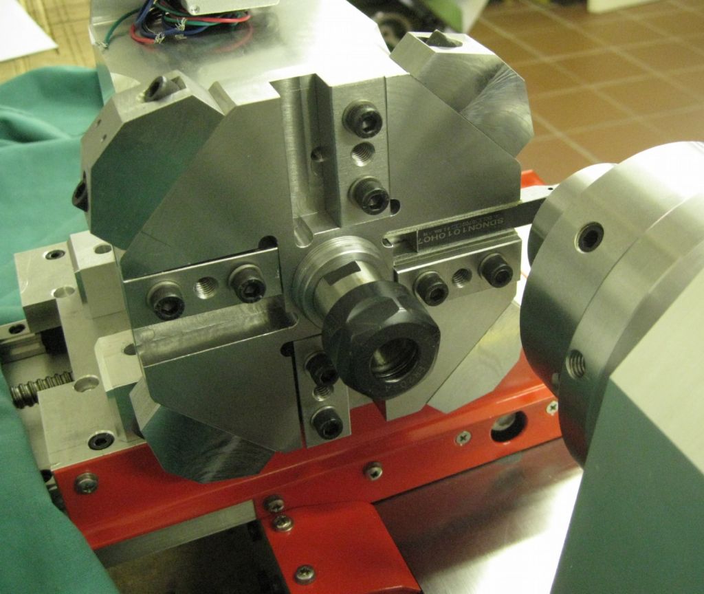
Titivated the ATC housing, losing a bit of excess weight, etc, set it all up with tooling and got the ATC center height set and trimmed.
Here slotting out the base underside with a parting tool in the shaper.
And then gapping the sides of the base as well.
Here skimming the last 1/100th from the base for center height setting.
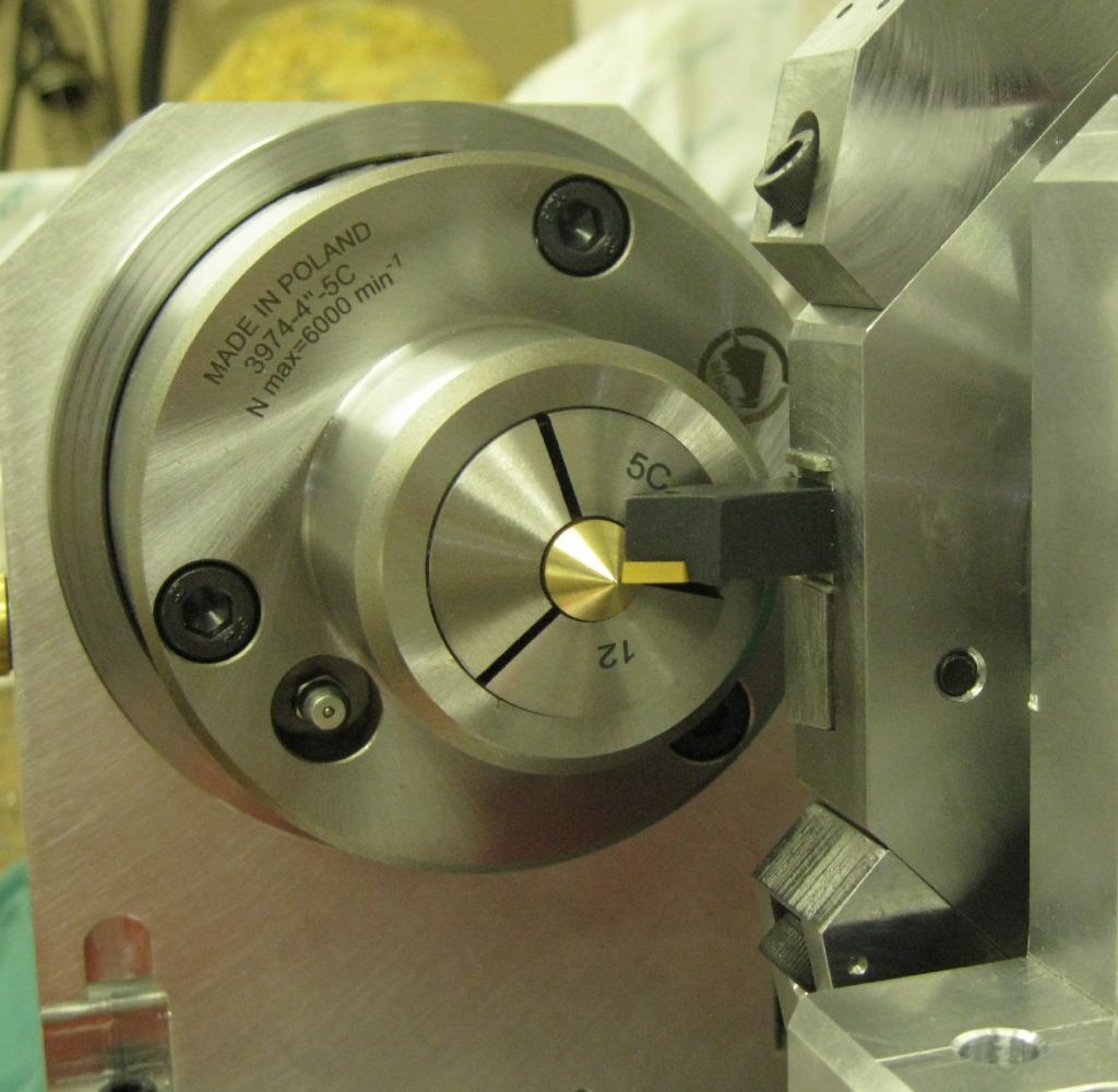
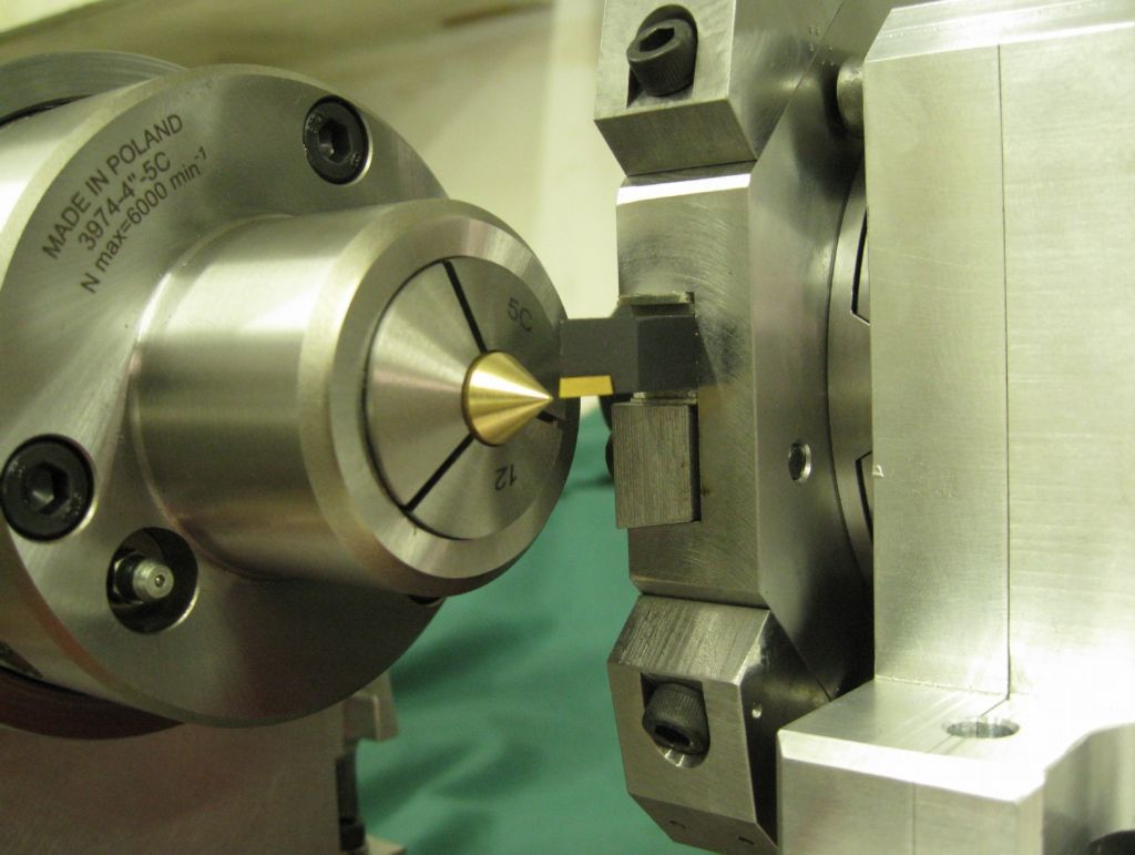
Center height setting was achieved and tested by fitting a sound piece of 20mm turned bar in the 5C chuck and setting the chuck for near zero runout. The center shaft of the ATC has an accurate 20mm bore, 40mm deep. Said shaft if pushed into that hole resists with trapped air pressure and falls out slowly over around 15seconds when inverted..
This hole was then verified for passage over the shaft as below – worked out nicely. The base of the ATC was skimmed in the shaper till is fitted just right. The ATC shaft central hole is fitted with an ER20 collet chuck after.
The ATC body-on-diet can be seen nicely below…lost nearly 350grams..
Lathe tool fitted (inverted) and aligned with center pip in 5C chuck.
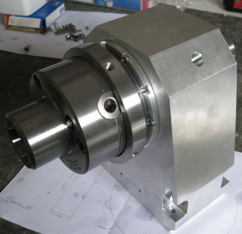
Top view – ER20 collet chuck fitted to tool plate – observe ample crash clearance to 5C chuck with lathe cutting tool brought to Lathe spindle axis center.
Have to make/fit a Hirth Coupler guard ring still – can see in this image how swarf would go onto the Hirth rings and possible get caught between the Hirth teeth when the coupler is opened – totally messing up the tool registration and position!
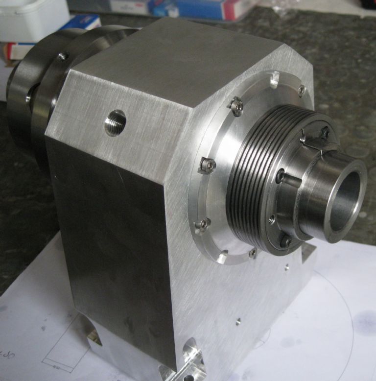
Rear side view of same
For those still following this effort..!
Joe
edit – spelling..
Edited By Joseph Noci 1 on 11/07/2021 16:41:37
-
AuthorPosts
- Please log in to reply to this topic. Registering is free and easy using the links on the menu at the top of this page.
Latest Replies
Home › Forums › Work In Progress and completed items › Topics
-
- Topic
- Voices
- Posts
- Last Post
-
-
Soldering to gold plating
Started by:
Stephen Harris 5 in: General Questions
- 7
- 8
-
16 July 2025 at 19:39
Maurice Taylor
-
Measuring a double Vee lathe bed Vee position
Started by:
Kim Garnett in: General Questions
- 4
- 8
-
16 July 2025 at 19:38
Kim Garnett
-
Drawings for constructing a Rolling Road
Started by:
Greensands in: Help and Assistance! (Offered or Wanted)
- 7
- 10
-
16 July 2025 at 19:16
 Bazyle
-
TurboCAD – Alibre File Transfers.
1
2
Started by:
Nigel Graham 2 in: CAD – Technical drawing & design
- 12
- 48
-
16 July 2025 at 19:11
Nick Wheeler
-
Model Engineer Magazine Collection
Started by:
mfengine1 in: Books
- 1
- 1
-
16 July 2025 at 17:56
mfengine1
-
How many spokes do I really need?
Started by:
 Fulmen
in: Related Hobbies including Vehicle Restoration
- 7
- 19
-
16 July 2025 at 17:13
 Fulmen
-
Boiler Design – issue 4765
1
2
…
8
9
Started by:
Charles Lamont in: Model Engineer & Workshop
- 27
- 212
-
16 July 2025 at 17:04
Paul Kemp
-
Advice to machine stationary engine base plate
Started by:
Greg H in: General Questions
- 3
- 5
-
16 July 2025 at 16:47
 JasonB
-
Silver steel crankshaft
1
2
Started by:
teamricky in: Stationary engines
- 9
- 35
-
16 July 2025 at 16:14
 JasonB
-
Herbert B drill information?
Started by:
Andrew Tinsley in: Workshop Tools and Tooling
- 1
- 1
-
16 July 2025 at 14:23
Andrew Tinsley
-
Electronic leadscrew pitching error
Started by:
 paulg 1
in: Introduce Yourself – New members start here!
- 4
- 21
-
16 July 2025 at 12:19
 JasonB
-
I’m Under Pressure
1
2
Started by:
howardb in: Related Hobbies including Vehicle Restoration
- 18
- 35
-
16 July 2025 at 10:21
 Michael Gilligan
-
motor and switch wiring Myford ML7
Started by:
1957jmh in: Workshop Tools and Tooling
- 7
- 12
-
16 July 2025 at 09:07
Les Jones 1
-
What Did You Do Today 2025
1
2
…
7
8
Started by:
 JasonB
in: The Tea Room
- 33
- 178
-
16 July 2025 at 06:39
Diogenes
-
Suds tray sealant
Started by:
Dave S in: General Questions
- 7
- 7
-
16 July 2025 at 01:31
cogdobbler
-
Error-Message of the day
Started by:
 Michael Gilligan
in: The Tea Room
- 8
- 14
-
15 July 2025 at 20:42
 Robert Atkinson 2
-
Sat nag
1
2
Started by:
duncan webster 1 in: The Tea Room
- 23
- 45
-
15 July 2025 at 20:02
Andy Stopford
-
Farm Boy
1
2
…
4
5
Started by:
Dalboy in: I/C Engines
- 15
- 106
-
15 July 2025 at 19:52
Dalboy
-
“swedish iron”
Started by:
moonman in: Materials
- 15
- 21
-
15 July 2025 at 16:52
Dave Wootton
-
Old plastic handled screwdrivers
Started by:
 Dave Halford
in: Workshop Tools and Tooling
- 13
- 15
-
15 July 2025 at 14:49
Georgineer
-
Another Day … Another ScumBag
1
2
Started by:
 Michael Gilligan
in: The Tea Room
- 15
- 36
-
15 July 2025 at 10:50
Graham Meek
-
Adjustable spanner thread direction
Started by:
 jimmy b
in: Workshop Tools and Tooling
- 9
- 13
-
15 July 2025 at 08:25
 Nicholas Farr
-
Screw cutting 1.25mm pitch on a Colchester Student.
Started by:
Kevin Nicholls in: Manual machine tools
- 7
- 17
-
15 July 2025 at 06:53
larry phelan 1
-
Volt/amp meter
1
2
Started by:
duncan webster 1 in: Electronics in the Workshop
- 15
- 43
-
15 July 2025 at 06:15
 Michael Gilligan
-
Variable DC power supply?
Started by:
Andrew Tinsley in: Electronics in the Workshop
- 4
- 10
-
14 July 2025 at 17:27
Andrew Tinsley
-
Soldering to gold plating
-
Latest Issue
Newsletter Sign-up
Latest Replies
- Soldering to gold plating
- Measuring a double Vee lathe bed Vee position
- Drawings for constructing a Rolling Road
- TurboCAD – Alibre File Transfers.
- Model Engineer Magazine Collection
- How many spokes do I really need?
- Boiler Design – issue 4765
- Advice to machine stationary engine base plate
- Silver steel crankshaft
- Herbert B drill information?


