Simon,
Thanks for the kind words! This project was a mental exercise started some 6 or 7 years ago and all the targets were formed in the mind way back with not much real thought applied to the work involved! And that is becoming a little overwhelming right now..But I am really keen to see the 'end' of it, or rather to see it working, so perseverance has it! From your MEW articles I found the reference to the Onshape info and did register there and take a look, thank you.
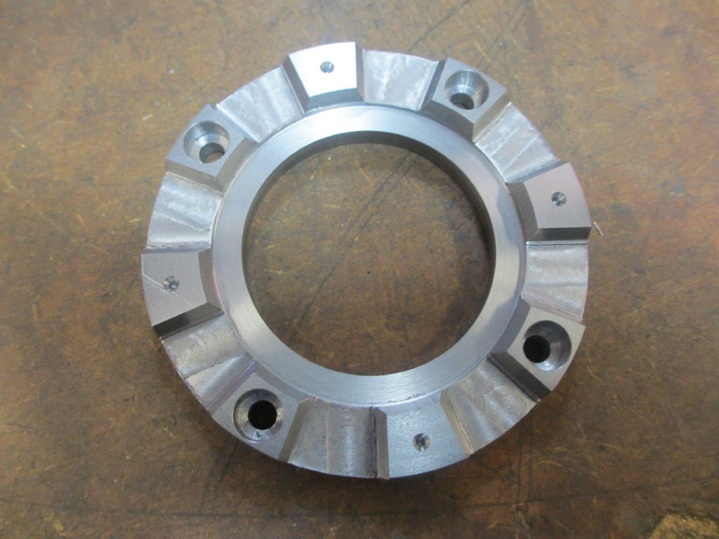
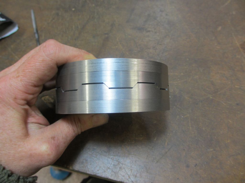
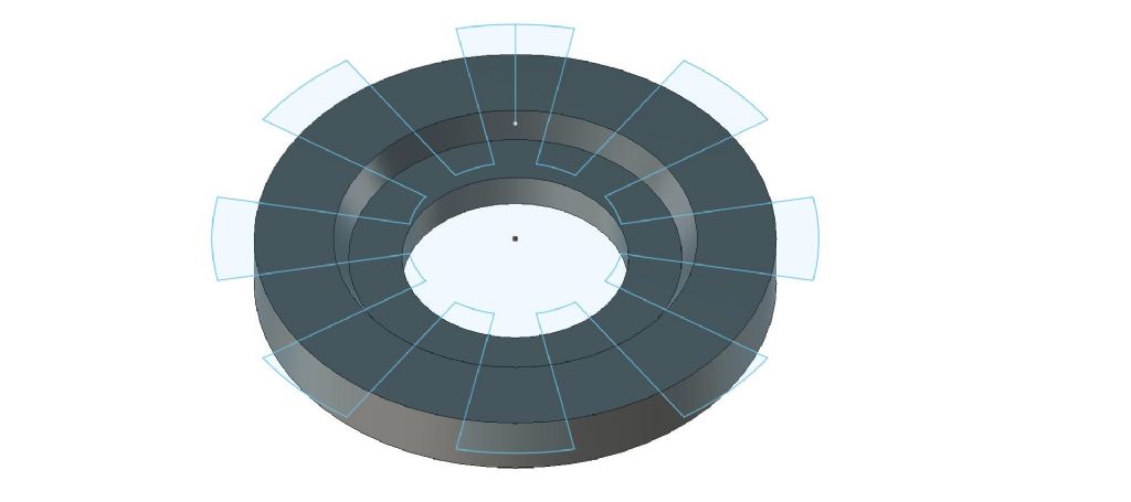
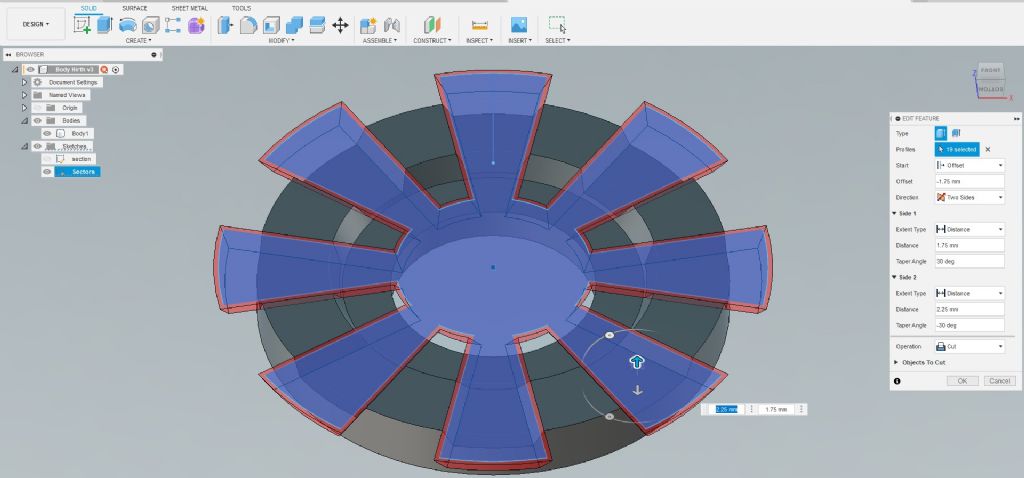
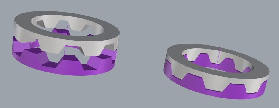
I suppose I will go the Hirth coupler route – as usual decisions are also driven by what materials I can get. I can get almost any thickness 'steel' plate cut to 'size' – Living about 50km from a Marine repair and servicing Harbour there is a lot of ship hull steel plate! Cut to size is relative – within 5mm or so, cut with rough plasma, leaving lousy cutting tool tip unfriendly surfaces, etc..No idea what the grade of steel is – the shaper does not approve of it. A challenge in every way here!
I want to try steer clear of hydraulics and pneumatics if possible – life is complicated enough with this thing, but who knows.
T.B.
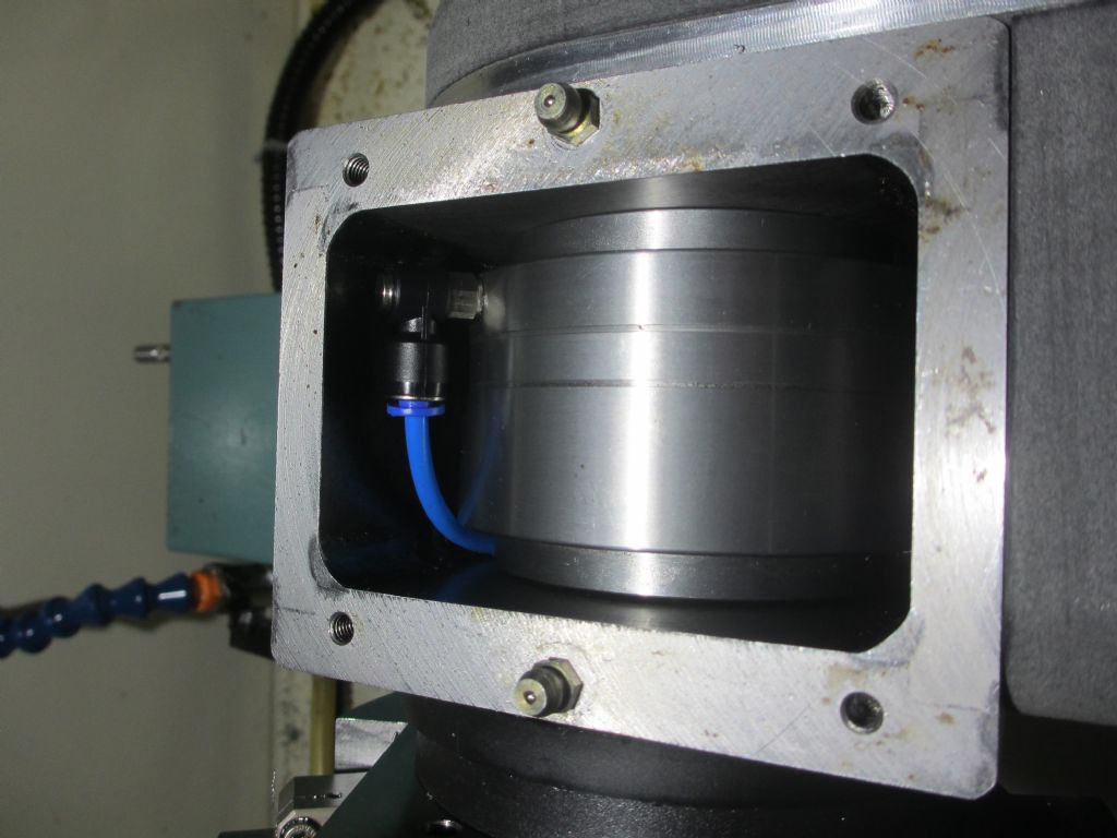
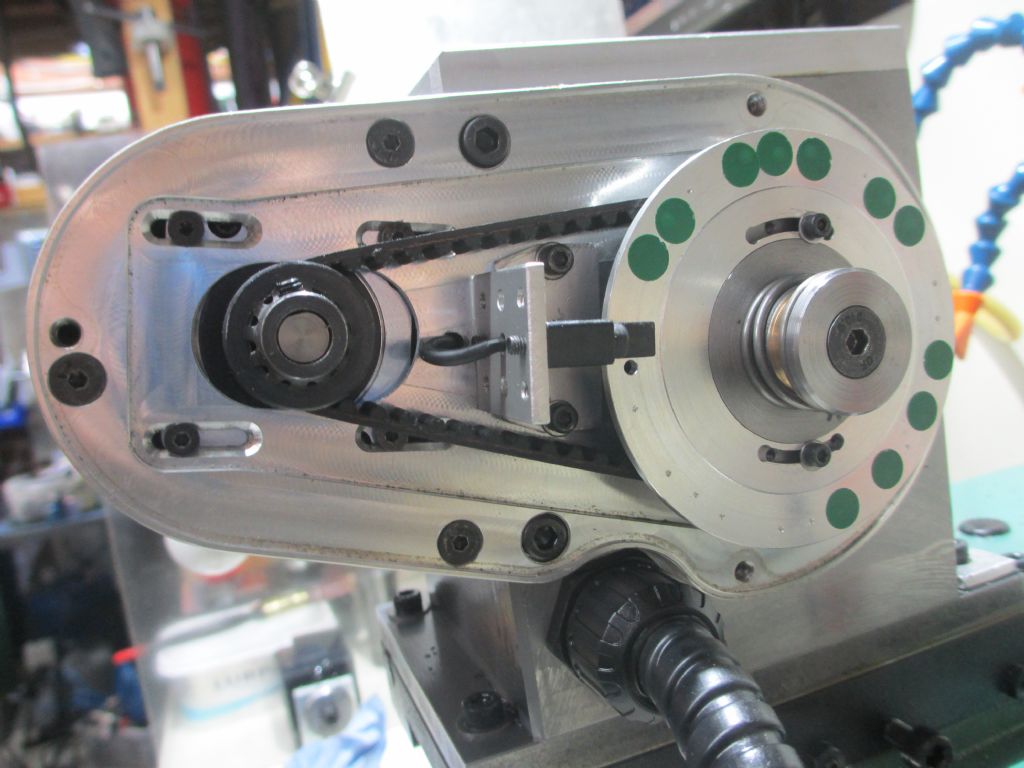
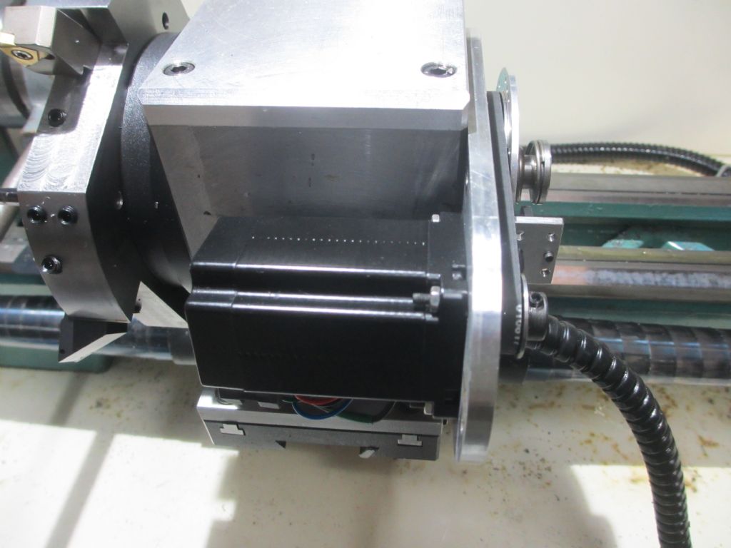
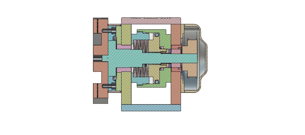
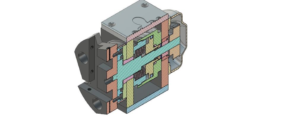
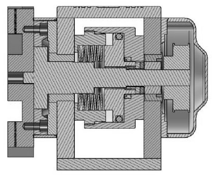
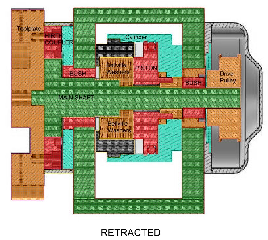
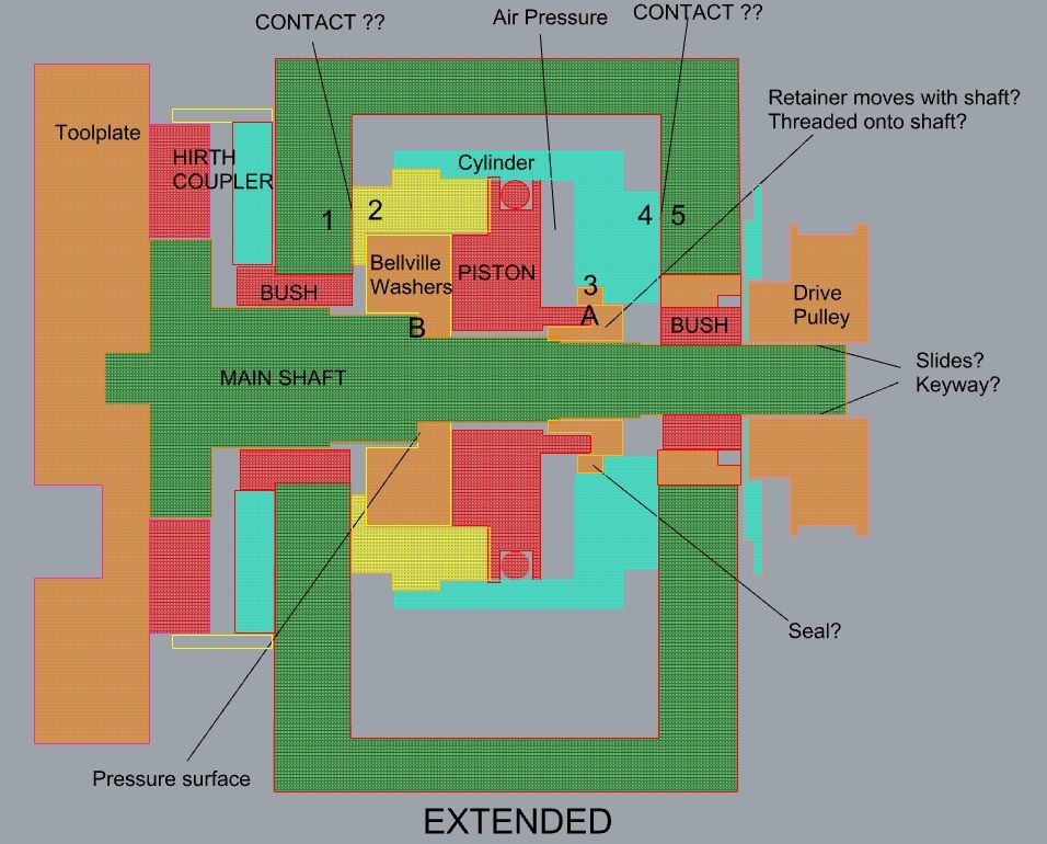
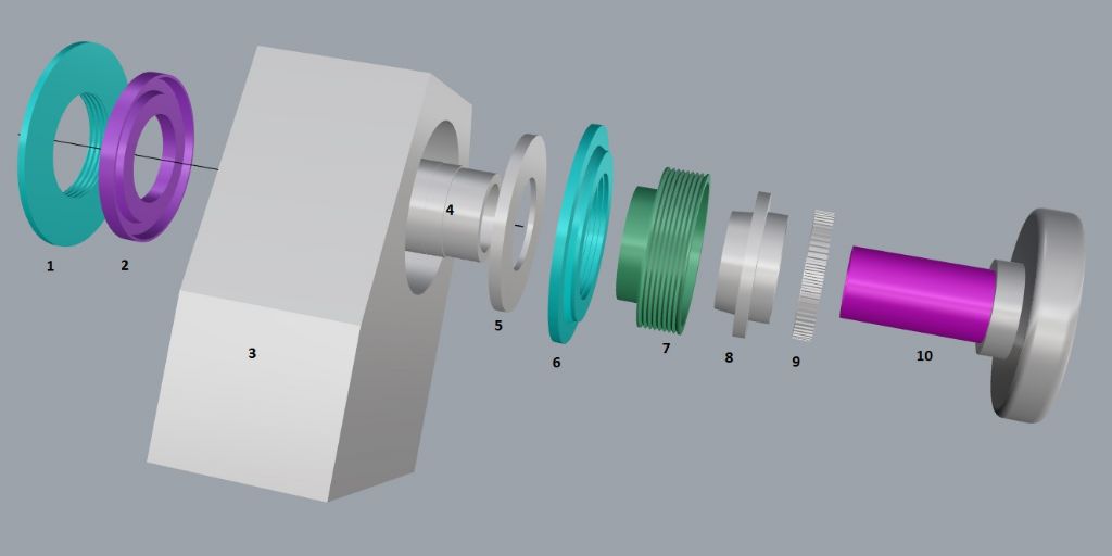
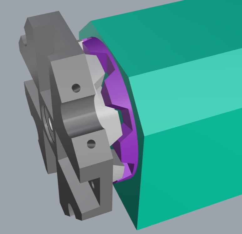
I am impressed by that ATC! Very nice and very well finished indeed. If I may be so bold – have you any detailed drawing or models of the internals that you would be willing to share ? The one thing I have not understood well enough yet is exactly how the tool plate and its shaft slides forward in the ATC block, to clear the Hirth teeth – In the many ATC DIY effort's I have seen on internet, that bit of detail is missing..I would assume the shaft rotates/slides in bushes rather than bearings? That implies that the shaft to bush fit must be very good to ensure rigidity, or does the Hirth coupling provide all the business end rigidity? How does the shaft slide in your design and what drives it? Your (3d printed?) covers hide many secrets!
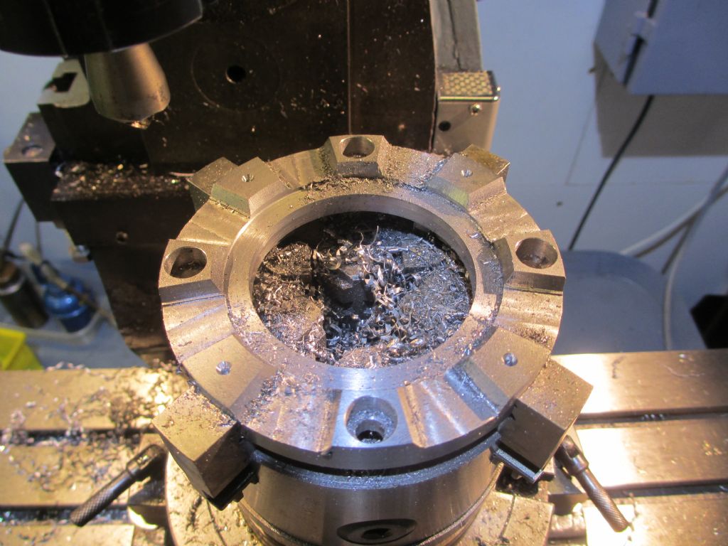
Your Hirth Coupler design as a bolt on has potential of being done on the shaper, so that will help!
Regarding tool / chuck clearances – When modelling my ideas I placed a standard lathe tool in the tool plate, its tip at chuck center height and about 3mm past stock center line, ie, such as a parting tool might move to when cutting just past center, and then located the boring tools/drill on the circumference of a circle around the lathe spindle axis, so that a 16mm boring bar would clear the 4inch chuck with 4 mm gap. Where that circle intersects a circle centered on the ATC spindle axis, the tools are placed. That ensures those tools will always clear the chuck OUTER periphery, so no crunches, and no shortened tools – well, unless the tools are longer than the chuck and smack the headstock
Very interested to see how you did your implementation of the ATC innards..
Thanks both..
Joe
T.B. – Sorry, an Edit –
You kindly offered to assist via a PM, which I will take you up on – just a thought though – seems there are a few folk 'dabbling' in this, and maybe some technical discourse on design within the forum may be of interest to all – if it becomes to heavy for the forum pages we can PM further?
Edited By Joseph Noci 1 on 21/04/2021 09:40:41
sam sokolik.


