Class 22 Diesel (next project)

Advert

Class 22 Diesel (next project)

Home Forums Locomotives Class 22 Diesel (next project)

Viewing 15 posts - 226 through 240 (of 240 total)
  • Author
    Posts
  • #564623
    Ron Laden
    Participant
      @ronladen17547

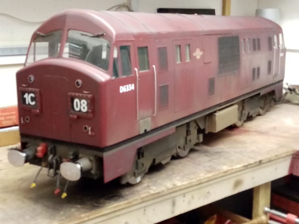
      Apologies for the thread dragging on but life and health (don't ask) just got in the way especially of late. However I did manage a few productive hours in the shop last week and the loco is as finished as its going to be. I still have the two cabs to fit out but they can wait.

      So all been well if I continue to improve the track test is not far away and I hope to get some video of how things go.

      Picture below of it desperate to be sitting on some rails.. smiley

      img_20210928_094806.jpg

      Advert
      #564635
      Ron Laden
      Participant
        @ronladen17547

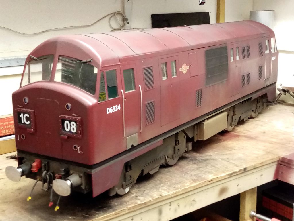
        A bit better focus I think.

        img_20210928_151216.jpg

        #564684
        Roger Best
        Participant
          @rogerbest89007

          Awesome. Great job.

          I know most readers will be more interested in steam engines but having driven a similar-sized battery electric engine at Basingstoke &DMES I can fully appreciate both the modelling and the fun of operation that this model offers. laugh

          #564700
          Jeff Dayman
          Participant
            @jeffdayman43397

            It's looking great Ron. Hope you get your rails wish soon! Cheers

            #564705
            Ron Laden
            Participant
              @ronladen17547

              Thanks Jeff/Roger

              Ron

              #566888
              Ron Laden
              Participant
                @ronladen17547
                The loco passed its track test it runs very well, good traction, quiet, good throttle response and very stable on the track, really pleased with it.
                The only thing I need to change is the gear ratio, its too high which I suspected it would be in using the pulleys that came with the motors. At full throttle its scary fast just too much so a smaller motor pulley should help cure that and possibly a max throttle stop.
                A very short clip of a club member enjoying some circuits in the sunshine
                #566920
                Jeff Dayman
                Participant
                  @jeffdayman43397

                  Looks and runs fantastic Ron! Well done! The driver looks happy on it, too. Did you have a few runs on it yourself? looks like a perfect day for it. Plenty of time later in the cold days to do the gearing adjustments.

                  #566965
                  Ron Laden
                  Participant
                    @ronladen17547

                    Thanks Jeff,

                    Yes I lost count of the number of runs I had there was only 3 steamers and me so a quiet day loco numbers wise, the steamer guys finished early so I had the track to myself and it was a lovely day. I have to say that I was taken by surprise at the acceleration and the top speed when I opened her up on the back straight which is not that long. It really pushed me back and guesstimating top speed at 15+mph and with the club speed limit at 5mph obviously far too much.

                    The motor pulleys that came fitted to the motors are 16T giving 4.5/1, I have some 12T pulleys which would give 6/1 but they are not one piece the toothed section is turned to a spigot with the boss pressed on and with a 8mm bore to fit the motor shaft the boss would come adrift. I could remove the armatures from the motors run between centres and turn them down to 5mm which would leave enough meat on the 12T pulleys but that is something to consider for the winter months. In the mean time it just needs some throttle control to keep things sensible.

                    Ron

                    #566979
                    JasonB
                    Moderator
                      @jasonb

                      Running well Ron.

                      #567018
                      Ron Laden
                      Participant
                        @ronladen17547

                        Thanks Jason, just pleased the design worked out OK.

                        Ron

                        #567033
                        duncan webster 1
                        Participant
                          @duncanwebster1

                          If you're into electronics it should be possible to make a unit that monitors and limits speed but still gives full chat for starting, hill climbing etc

                          #567042
                          Ron Laden
                          Participant
                            @ronladen17547

                            That's a good idea Duncan but I,m afraid I am not into electronics to that level. I am OK with basic wiring and ok with simple electronics if I am shown what to do but I don't have the understanding to design a unit as you describe.

                            I still want to change over the ratio from 4.5/1 to 6/1 which will increase the pulling power and offer some reduction in top end speed.

                            Ron

                            Edited By Ron Laden on 16/10/2021 14:15:34

                            #567055
                            Roger Best
                            Participant
                              @rogerbest89007

                              Its always better to get the ratio right for the characteristics of the motors. Less likely to burn them out.

                              The weathering looks great on the video.

                              #567069
                              SillyOldDuffer
                              Moderator
                                @sillyoldduffer
                                Posted by Ron Laden on 17/08/2021 16:06:37:

                                Hi guys,

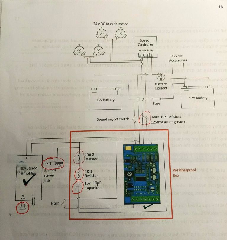
                                … what I dont understand is how the 16v capacitor, 1K ohm and 100 ohm resistors and the way they are connected to the amplifier stereo jack are working. … it would just be good to know.

                                img_20210817_153153.jpg

                                Late answer, but here goes.

                                The 100Ω and 1kΩ resistors form a potential divider. It's purpose is to match the output of the sound board to the level required to drive the amplifier. Most amplifiers are quite sensitive and if the input signal is excessive, the amplifier will clip and otherwise distort the audio sent to the loud speaker. The divider's ratio is 10:1, which would be right, for example, if the amplifier input expected 1mV and the sound board output a 1V signal. It's a fixed volume control.

                                A useful property of capacitors is they block DC current whilst allowing AC to flow. The 16µF capacitor is a isolating precaution: it stops any DC that might happen to be on the sound board output from confusing the amplifier.

                                The divider and capacitor ensure the right level and type of voltage are fed from the sound board to the amplifier. The combination will also act as a tone control, but like as not the effect has been ignored by the designer. If the output sounds a bit shrill, or lacks bass, try increasing the size of the capacitor. Anything up to 220µF should do.

                                Although the amplifier is stereo the Sound Card is mono. The Potential divider drives both Right and Left Channels, a mild bodge. Reason for this is likely cost. Small stereo amplifiers being common as muck are often cheaper and easier to source than their mono equivalents. It's nothing to worry about.

                                Dave

                                #567253
                                Ron Laden
                                Participant
                                  @ronladen17547

                                  Thanks Roger, I must admit I am a fan of weathering providing its not over done or done badly. If done reasonably well I think it can add realism to the subject, though its not everyones cup of tea and I think the majority prefer their locos looking pristine which is fine, everyone to their own.

                                  Dave, thanks for the explanation on the amplifier circuit and what each component does.

                                  I learnt something today by chance whilst watching a video, although a lot of switched circuit breakers look the same there is AC and DC types and they are different animals not to be interchanged. Not knowing there is the two types I just ordered one at the time and I cant remember any reference to AC or DC unless I missed it. So I think it probable I have an AC type in the loco when of course it should be a DC so will have to get one on order.

                                  Goes to prove that too little knowledge can be dangerous.

                                Viewing 15 posts - 226 through 240 (of 240 total)
                                • Please log in to reply to this topic. Registering is free and easy using the links on the menu at the top of this page.

                                Advert

                                Latest Replies

                                Home Forums Locomotives Topics

                                Viewing 25 topics - 1 through 25 (of 25 total)
                                Viewing 25 topics - 1 through 25 (of 25 total)

                                View full reply list.

                                Advert

                                Newsletter Sign-up