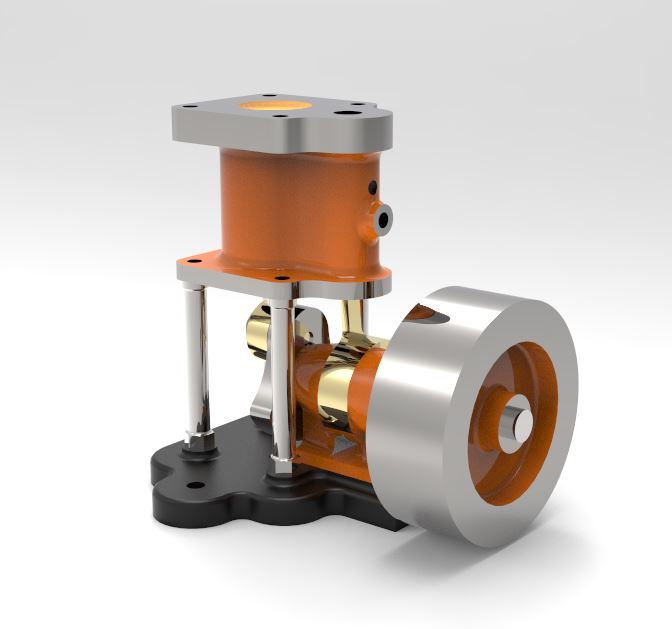
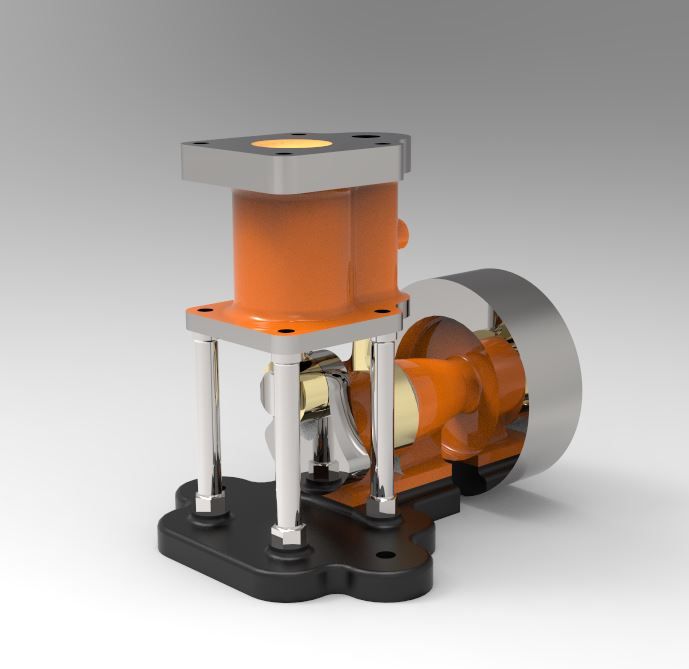
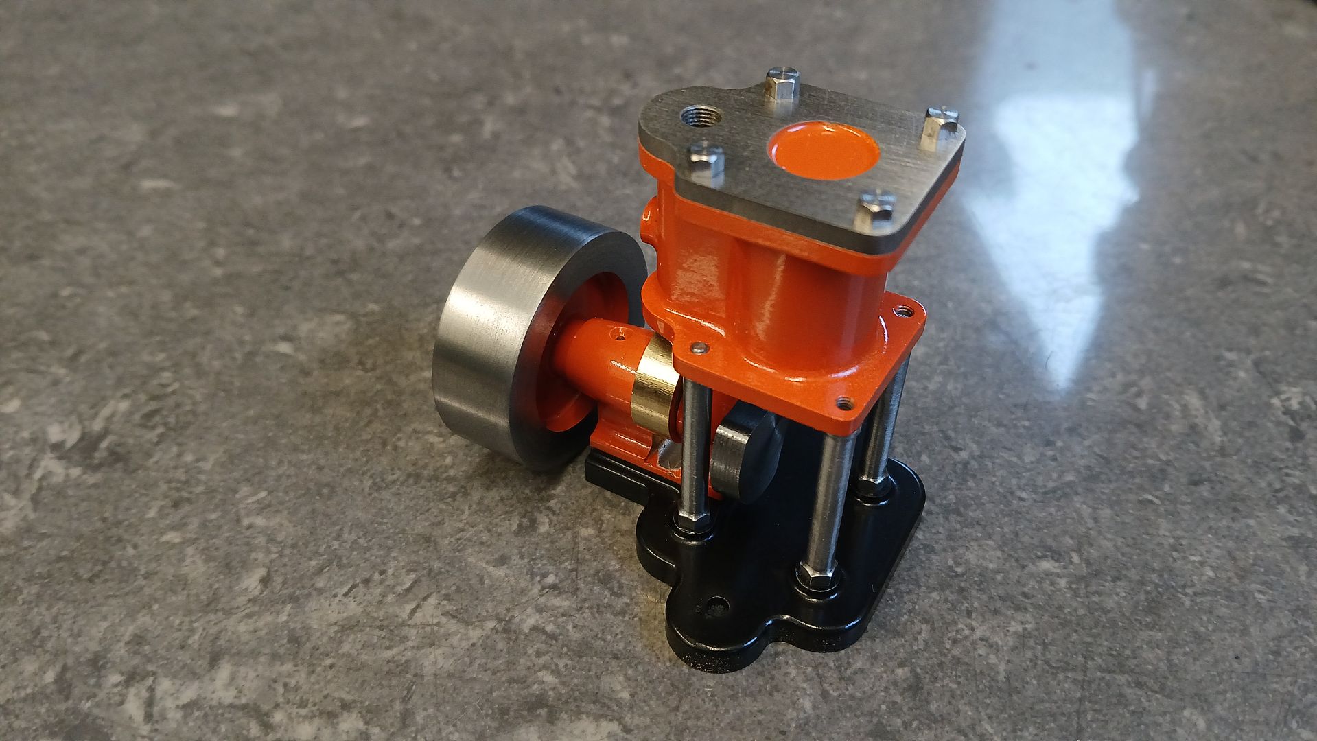
This time the subject is Clarkson’s “Single Acting Vertical” which was a 1/2″ x 1/2″ piston valve engine no doubt destined for use in a pond boat and quite likely with a flash steam boiler though a standard boiler will also do. Castings are still available from Blackgates but I decided to make mine from scratch and as has become my norm in metric, a scale of 24mm:1″ gives a bore and stroke of 12mm x 12mm and most of the other numbers work quite well. I just had to adjust a couple of diameters such as 3/16″ flywheel bore up to 5mm where I wanted a reamed hole as I don’t have a 4.5mm reamer.
The old Clarkson drawings are quite good for this one and I did not find any glaring errors or missing sizes. Apart from a few cosmetic changes to suit my tastes it was all very much as per the original and did not take long to draw up in Alibre.
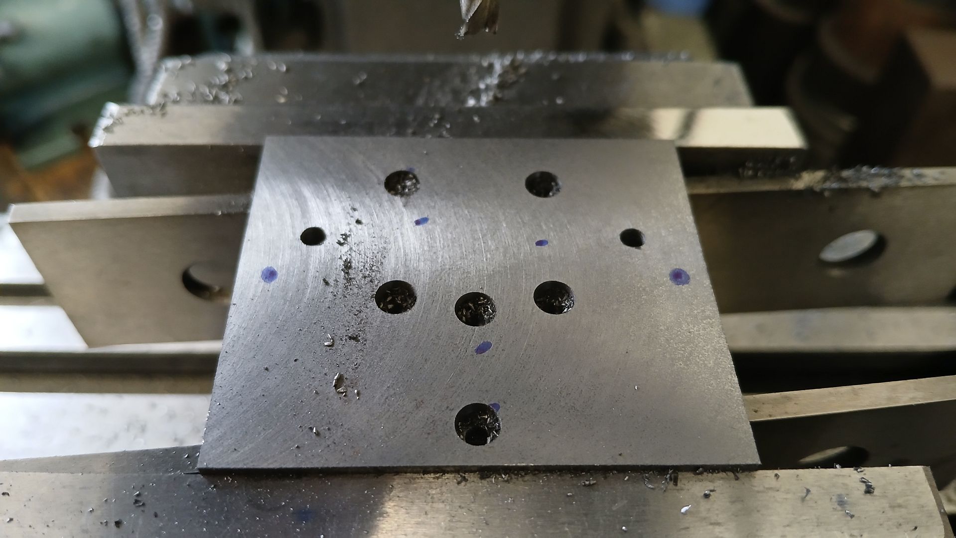
Starting with the sole plate a piece of cast iron was cut from an old unwanted casting and milled to 1mm oversize length and width and to a finished thickness of 6mm. The various holes were then drilled and the ones for screws counterbored. I find the hex sockets in M2.5 Csk screws don’t last that long so deviated from the drawing by using cap heads.
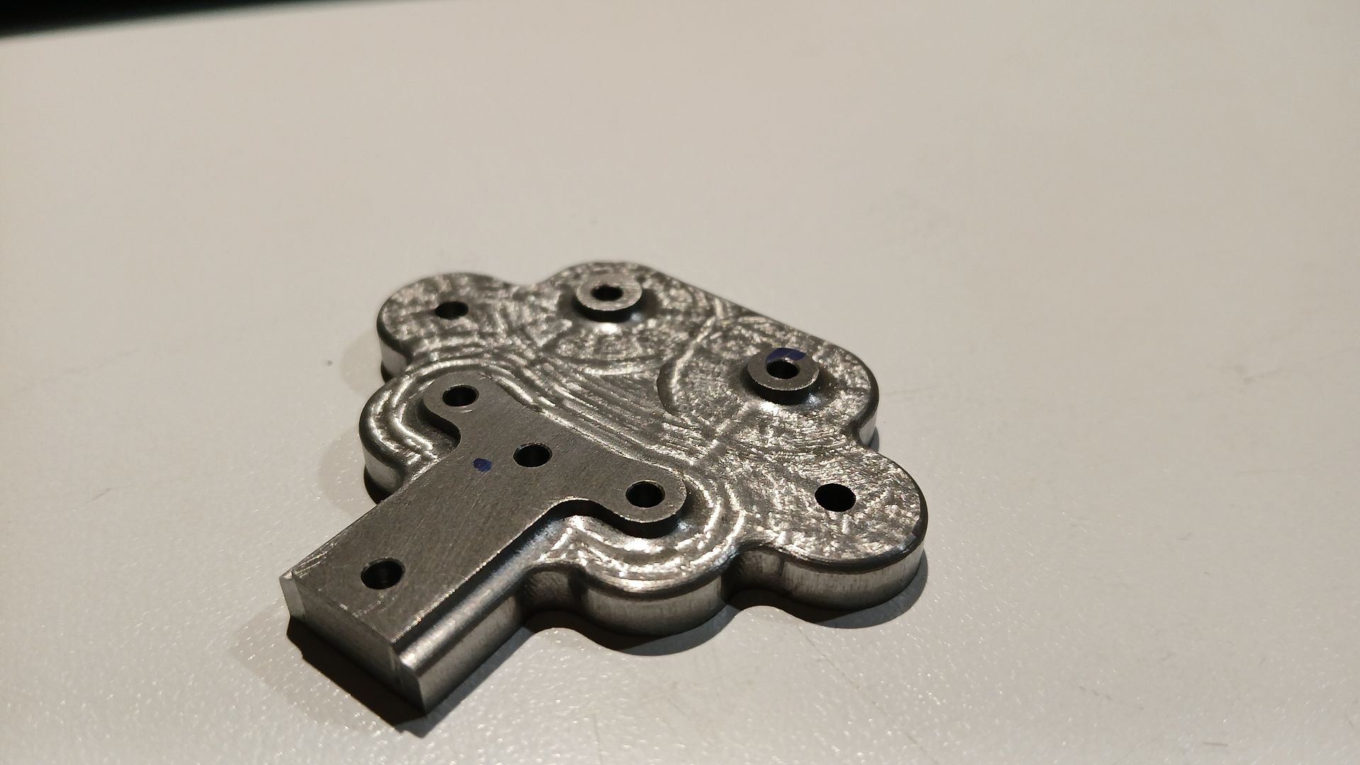
Making use of the four holes for the columns a tooling block was drilled and tapped to the same pattern and the blank screwed to that and the CNC used to do the rest. It would not be a difficult shape to mill manually and the raised bosses could be bonded into shallow counterbores with JB Weld.
Although there are visible tool patterns they cannot be felt and will be hidden when painted.
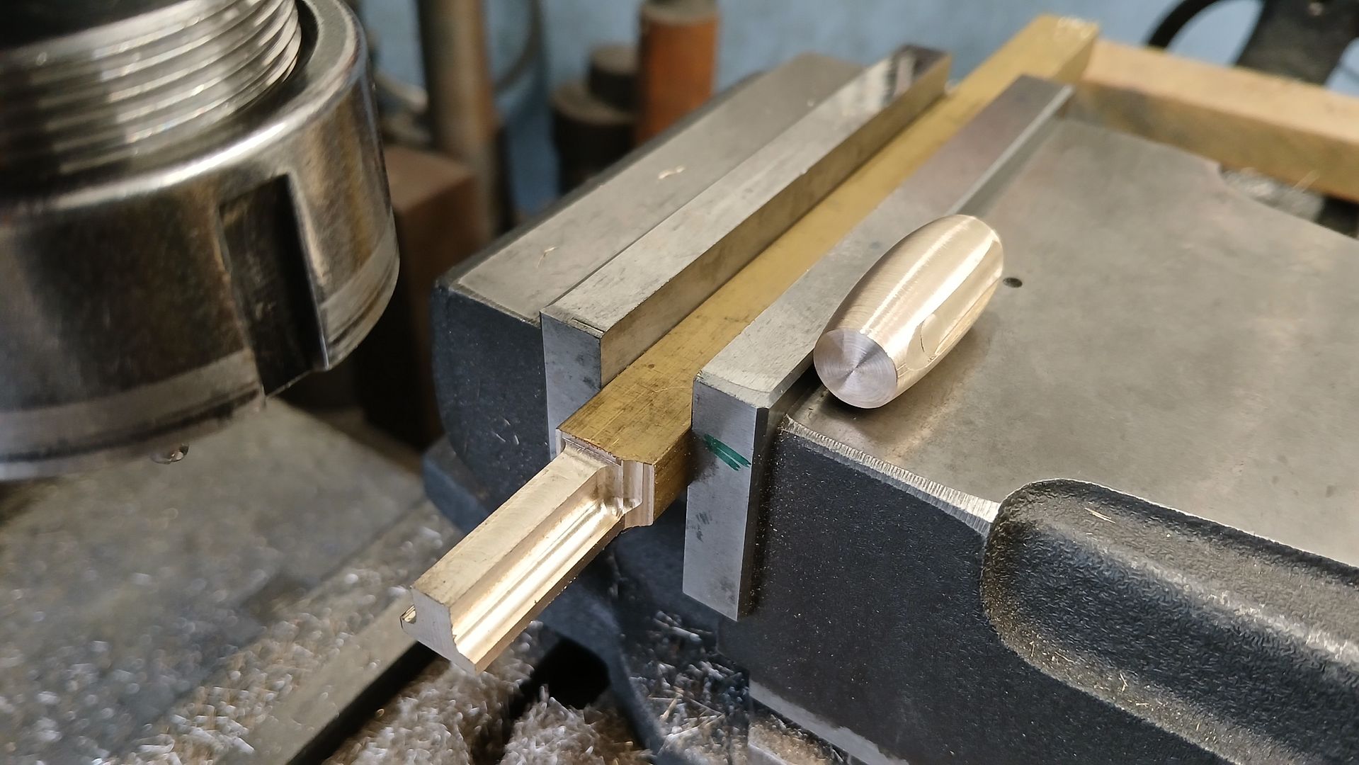
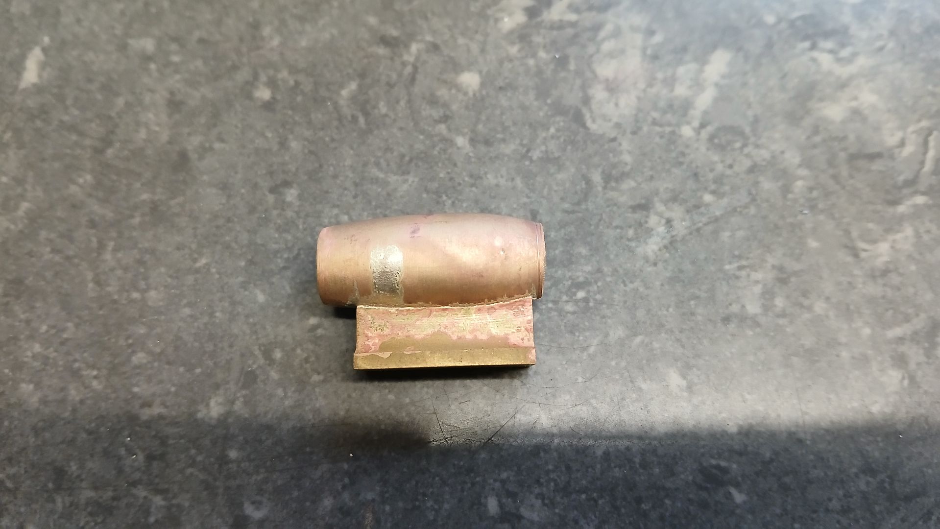
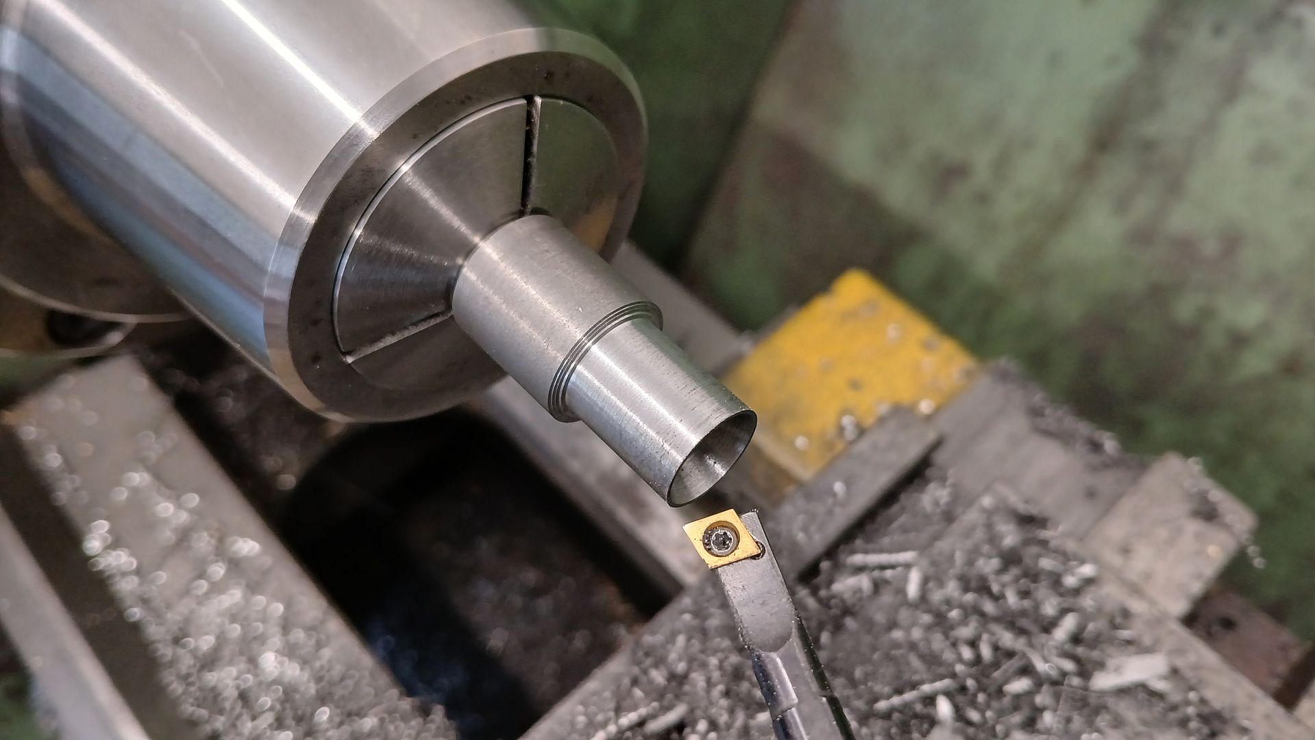
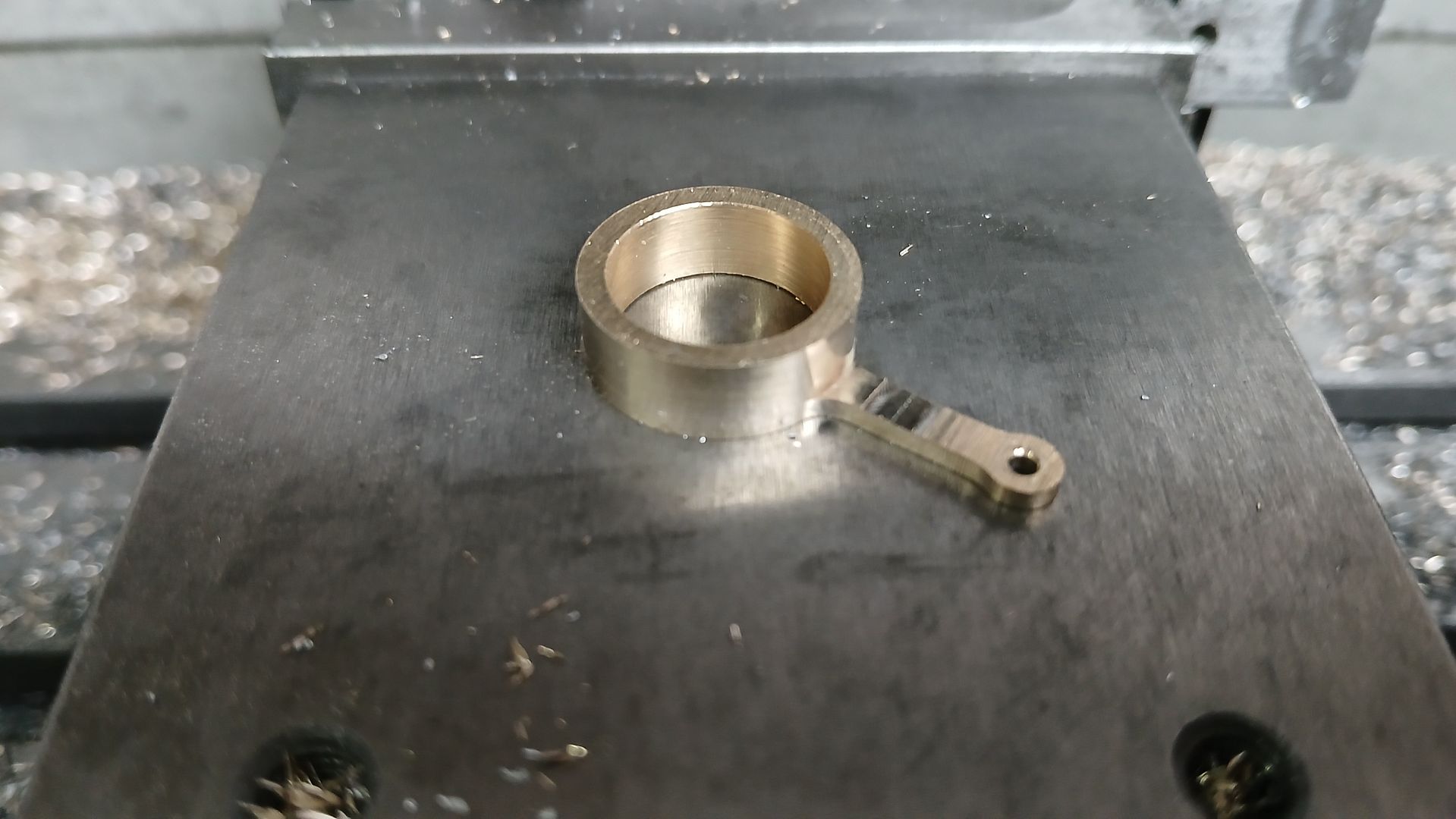
The bearing and it’s pedestal were fabricated from a bronze barrel that was shaped freehand on the lathe before having a locating slot milled along it’s bottom and a “tee” shaped piece for the pedestal milled from some brass bar. Which were then silver soldered together
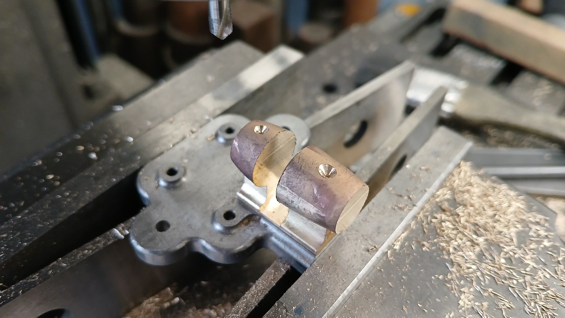
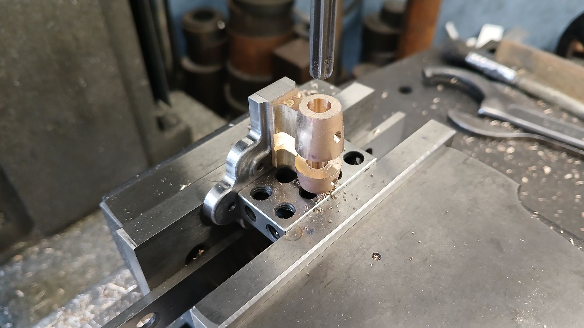
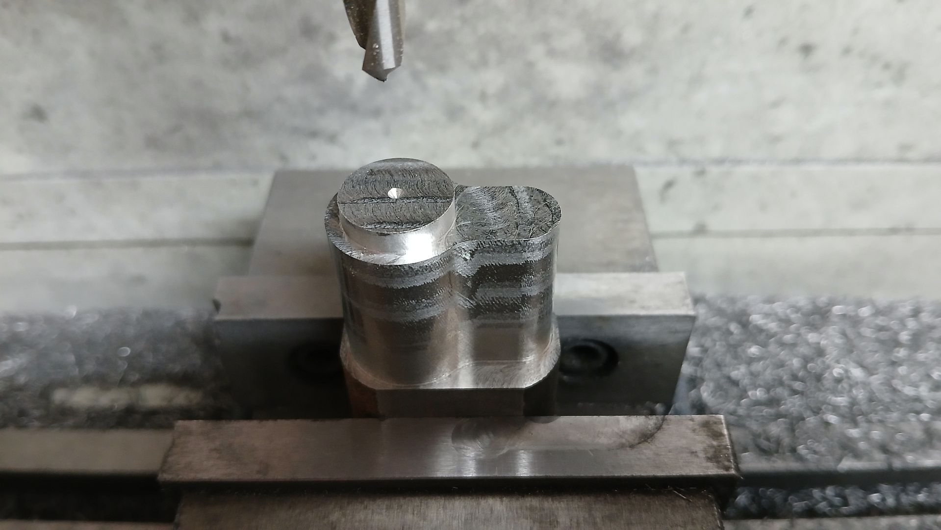
I screwed the fabrication to the sole plate to make it easier to hold and milled either end back to final length. Then a 6mm wide slot for the eccentric and it’s strap. There were no oil points shown on the drawing so I used a spot drill to make a couple of conical recesses, the 1.2mm oil holes were drilled through after the main crankshaft hole was drilled and reamed to avoid them wandering.
Graham, unfortunately I am running out of display space so a 12″ x 12″ is unlikely plus I would need a much bigger compressor!
I do have the Spartan drawings, they were a pull out in an old ME. It’s a bit of a steam meets model IC engine as the cylinder liner and top drain cock have the look of a diesel but the A frame and bedplate are very much the usual steam design.
An 18mm bore one would result from the same scaling factor but would I get away with one or need to make two so that I have both poppet and piston valve versions? The A frame would be quite an easy fabrication of two Tee sections and the square top
I’ll have to see if I can locate the text and have a read up about it, I suspect it was meant to perform well with flash steam and at quite high rpm. This little Clarkson has just nudged the tacho over 2500rpm this morning so I would say it went back together OK after painting.
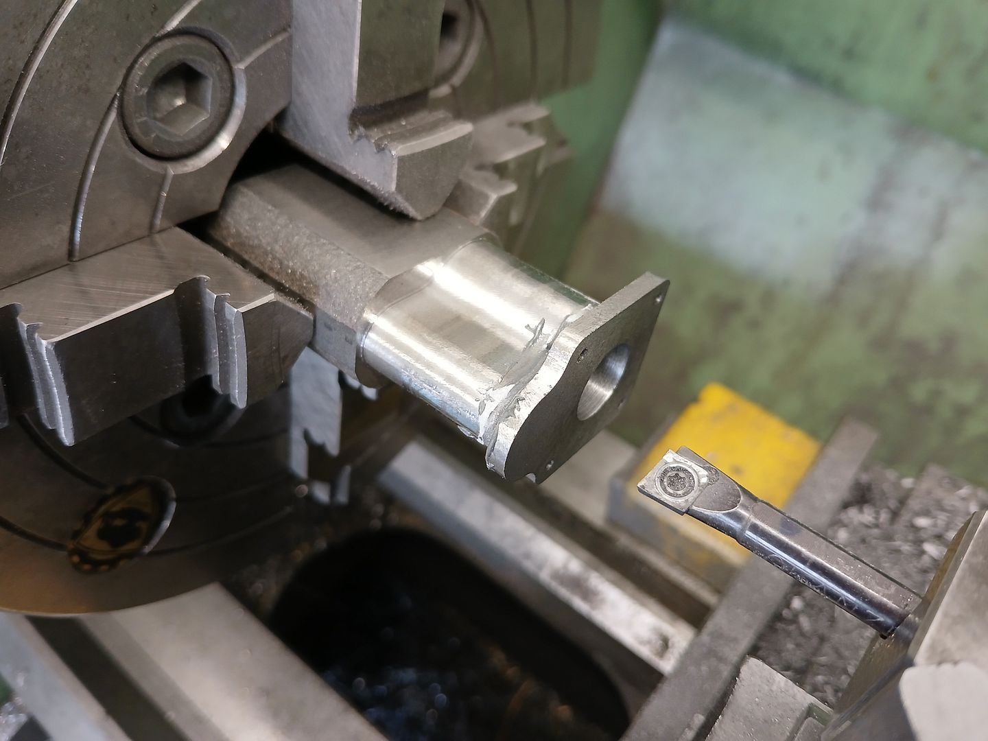
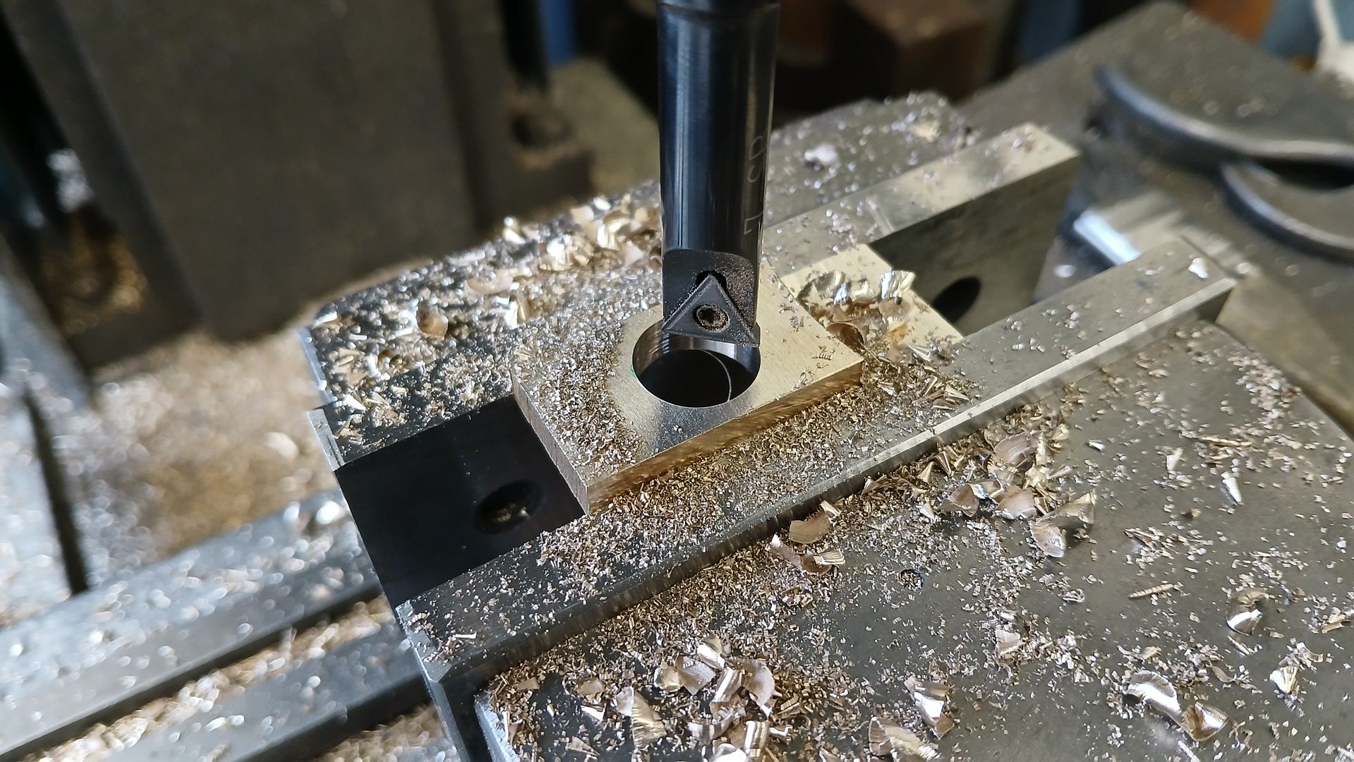
I debated about how to make the cylinder which I wanted to do from Cast Iron. I could have CNCd it from a solid block cutting from both sides but as not that many people have a CNC I went for a JBWelded fabrication which although I did use the CNC to cut the parts they could also be done manually.
The first job was to prepare three flat rectangles, two for the flanges and another for the cylinder end cover. These had the four holes drilled into them so that I could screw them to a tooling block to shape the profile and also cut a decorative recess in the top of the cover.
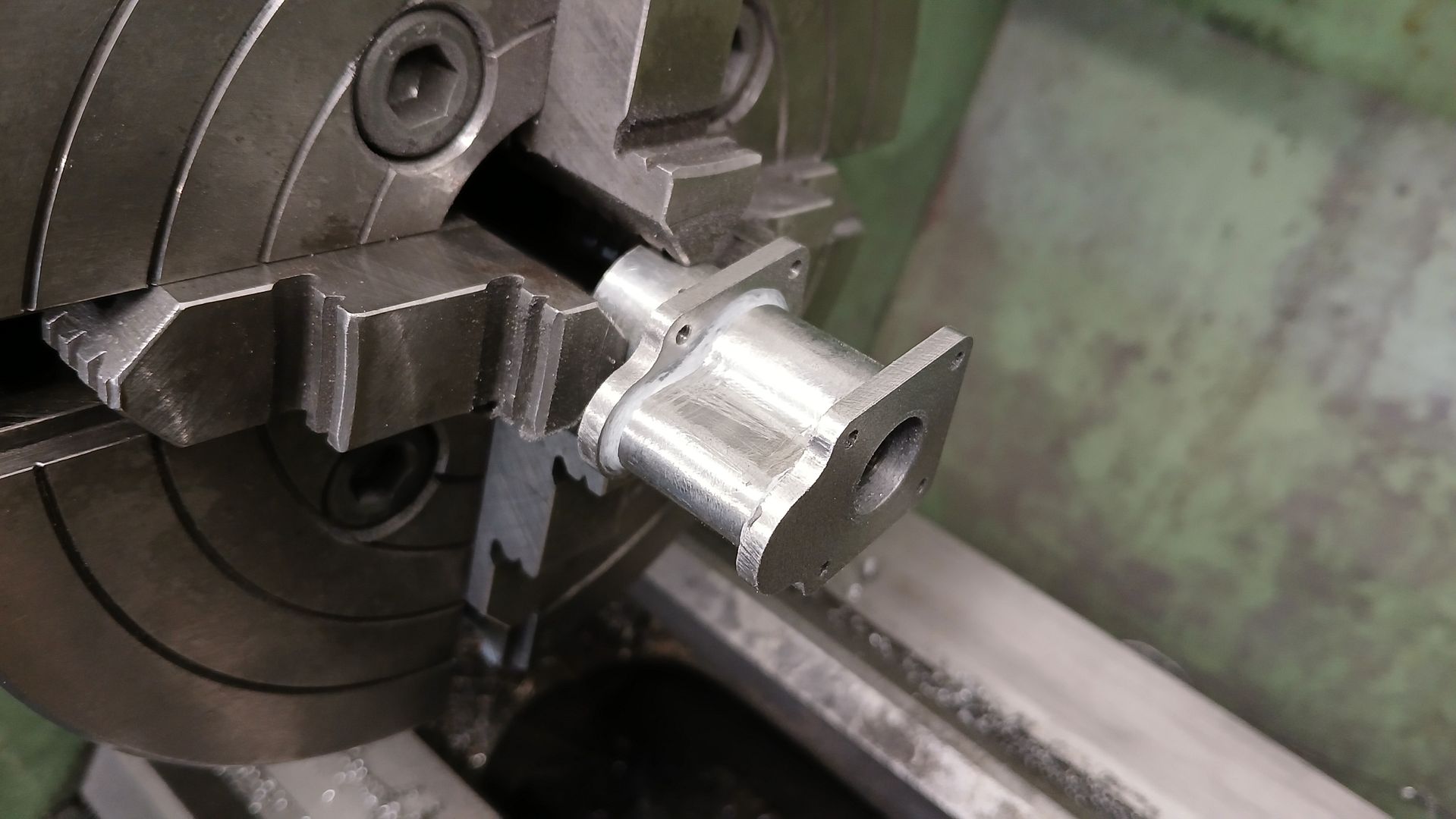
The cylinder itself was cut from a piece sawn from an unused casting including a spigot to locate one of the flanges and a spot drilled hole so it could be clocked up in the 4-jaw.
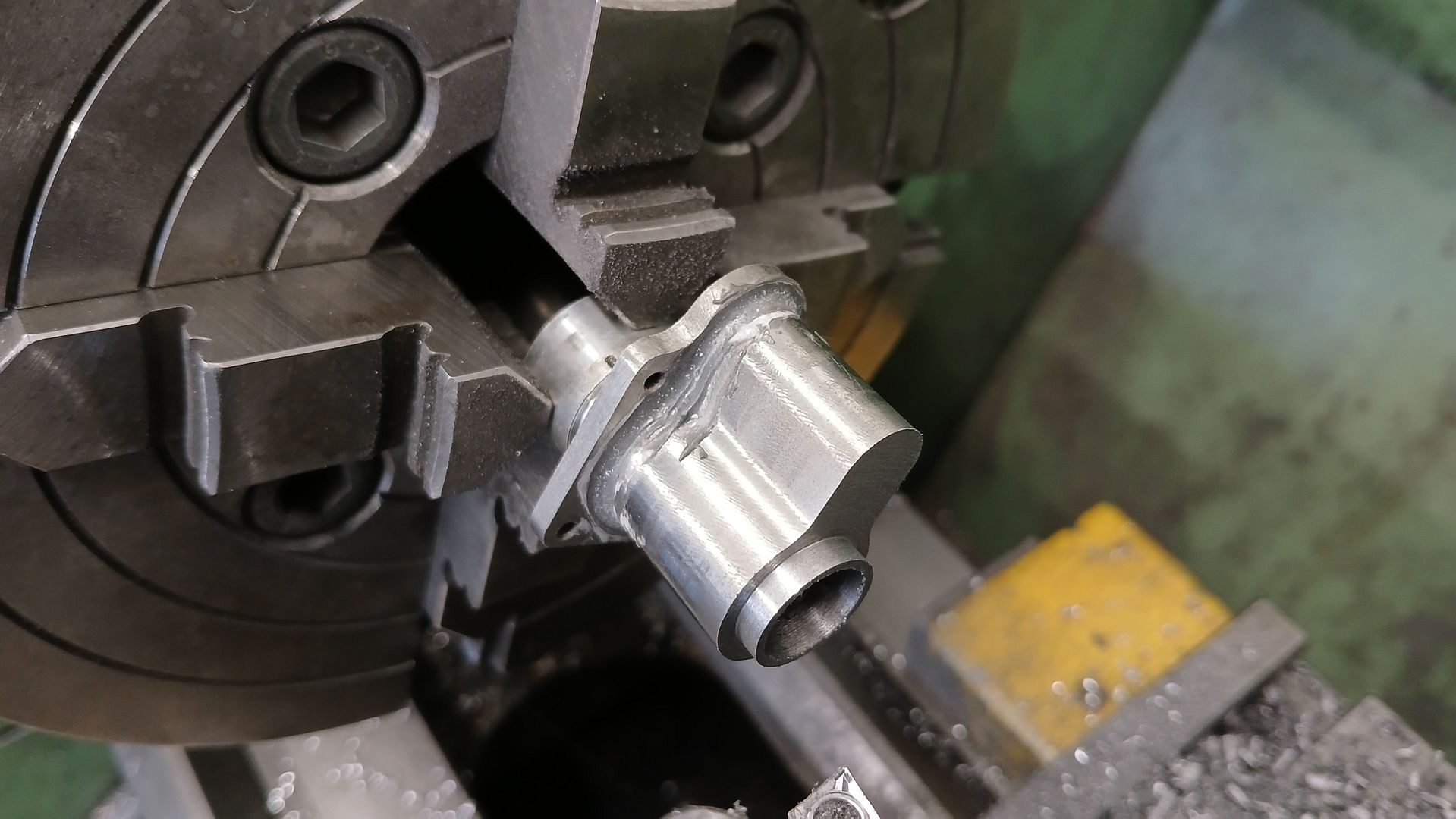
One of the over thick flanges was bonded onto the spigot with JB Weld and after leaving it to go off the cylinder was clocked true in the 4-jaw to be drilled and bored to 12mm, I also faced off the flange at the same setting so that it was true to the bore and marked this as the bottom flange.
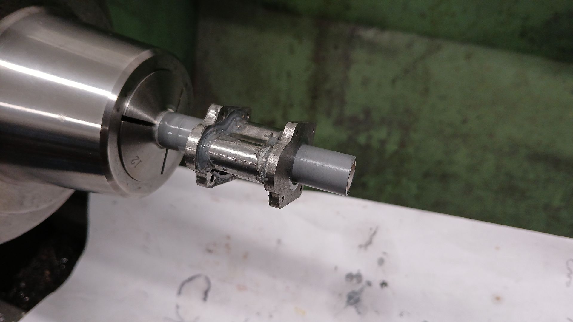
An old expanding arbor was turned down to fit the bore of the new cylinder
Using the arbor the other end of the cylinder could have it’s spigot machined ready to bond on the top flange. And once that had set it was faced back to final size
The bore was then lapped down to 600g
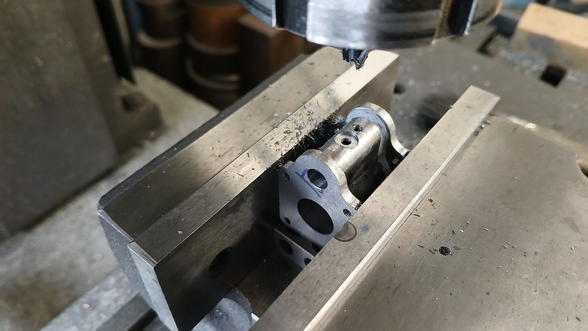
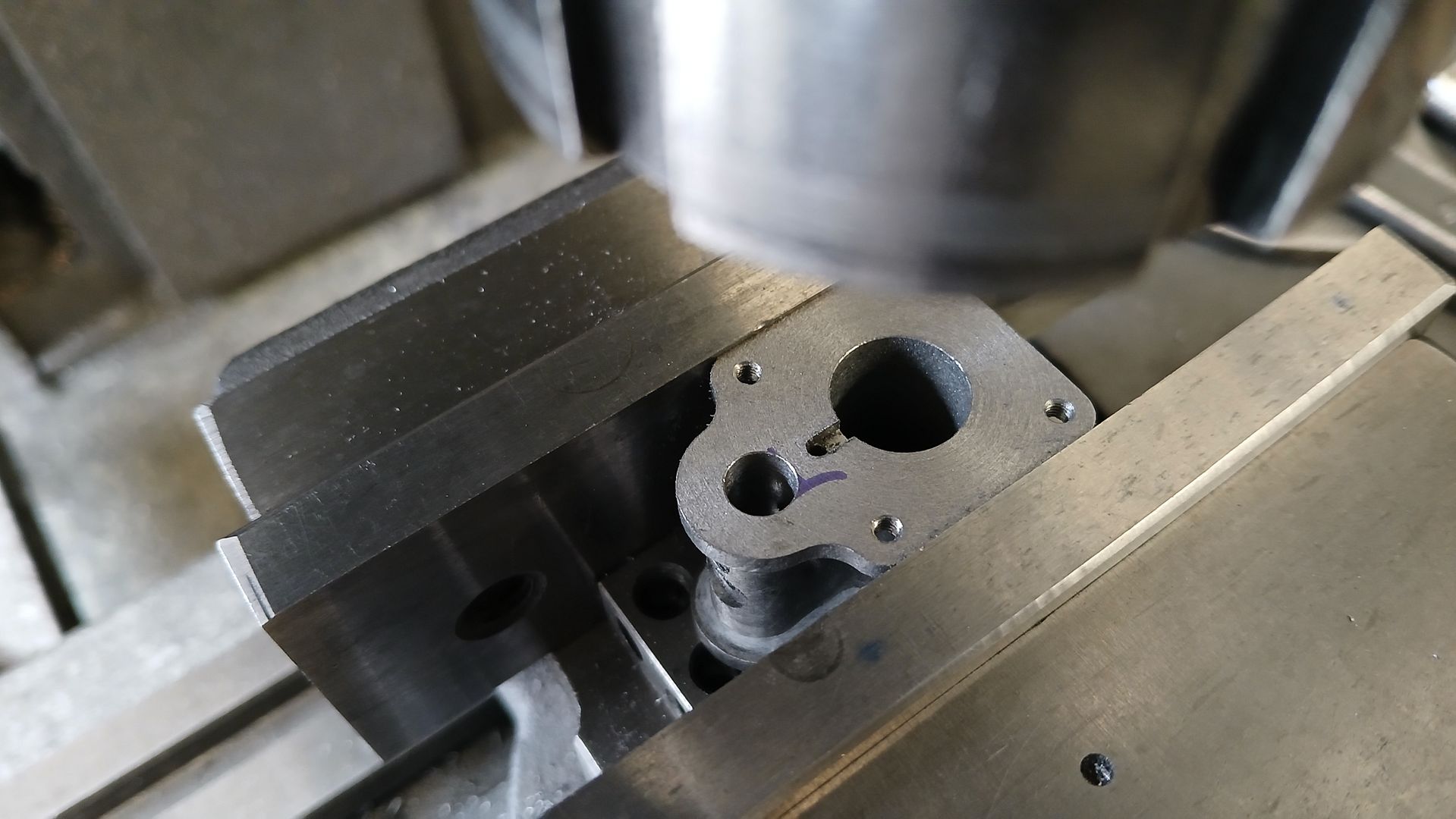
Over to the mill and the valve hole was drilled 5.8mm and then reamed to 6mm. Then with it horizontal the inlet hole was drilled and counterbored for a small threaded boss to be bonded in. The tapped hole next to it connects the valve chamber to a vertical hole which takes the air/steam up to the top of the cylinder, the outer part of this hole gets plugged.
From the top the hole down to the plugged one is drilled and a connecting slot to the main bore milled 1.5mm x 1.5mm.
Your scale of 24 mm to the inch inch is a new one to me and it works nicely. I have for a long time used 1/32″ to equal 1 mm when I want to make something designed in inches into metric and slightly, (aprrox 25%) larger. Alternatively I have used 1/16″ to equal 1 mm when I want to make something in metric but smaller, (approx about 1/3rd). This was the scale I chose to make my Quorn from the solid and my series of ETW’s Gemini engines, (2, 3 and V4 cylinders).
I see that the Black Night thing is a ‘new release’ and not an old one – Bing, Dave C., the change from BST, dementia, or all of the above are messing with my mind – sure I looked at MEW very late last week to check if the new one was up and we were still on the ‘Atkinson’ edition..
Graham, I too have used those two conversions several times depending if I want bigger or smaller and once did a version of the same in both sizes.
The mathmatical 25.4mm to the inch does not result in simple sizes for things like shafts and although some people kid themselves that they are working in metric will still pick up a 3/16″ reamer for that 4.76mm hole.
25mm to 1″ does not fare well as the common fractions of 1/2, 1/4 and 1/8 soon get into decimal places.
So I have found 24mm to 1″ works reasonably well as 1/2″ is 12mm, 1/4″ is 6mm, 1/8″ is 3mm and 1/16″ 1.5mm. It is only where you get a 3 or similar in the fractions that a decision needs to be made whether to go up or down to suit stock sizes or whole mm cutters. Eg 3/8 you can go either way to the common 8mm or 10mm and 3/16mm either 4 or 5mm. lengths and thicknesses are a bit more forgiving a 3/16 scales to 4.5mm which is easy enough to measure or set a handwheel to.
I intend to use your system in the near future to produce a version of the Stuart ST oscillator Vee twin. One will be in brass as per normal, machined from the solid, but the other will be mainly Delrin, Nylon and Stainless Steel. The latter I intend to use driven by an electric motor to provide a reliable aeration pump for the garden pond.
The piston was turned, bored and the skirt chamfered to clear the conrod.
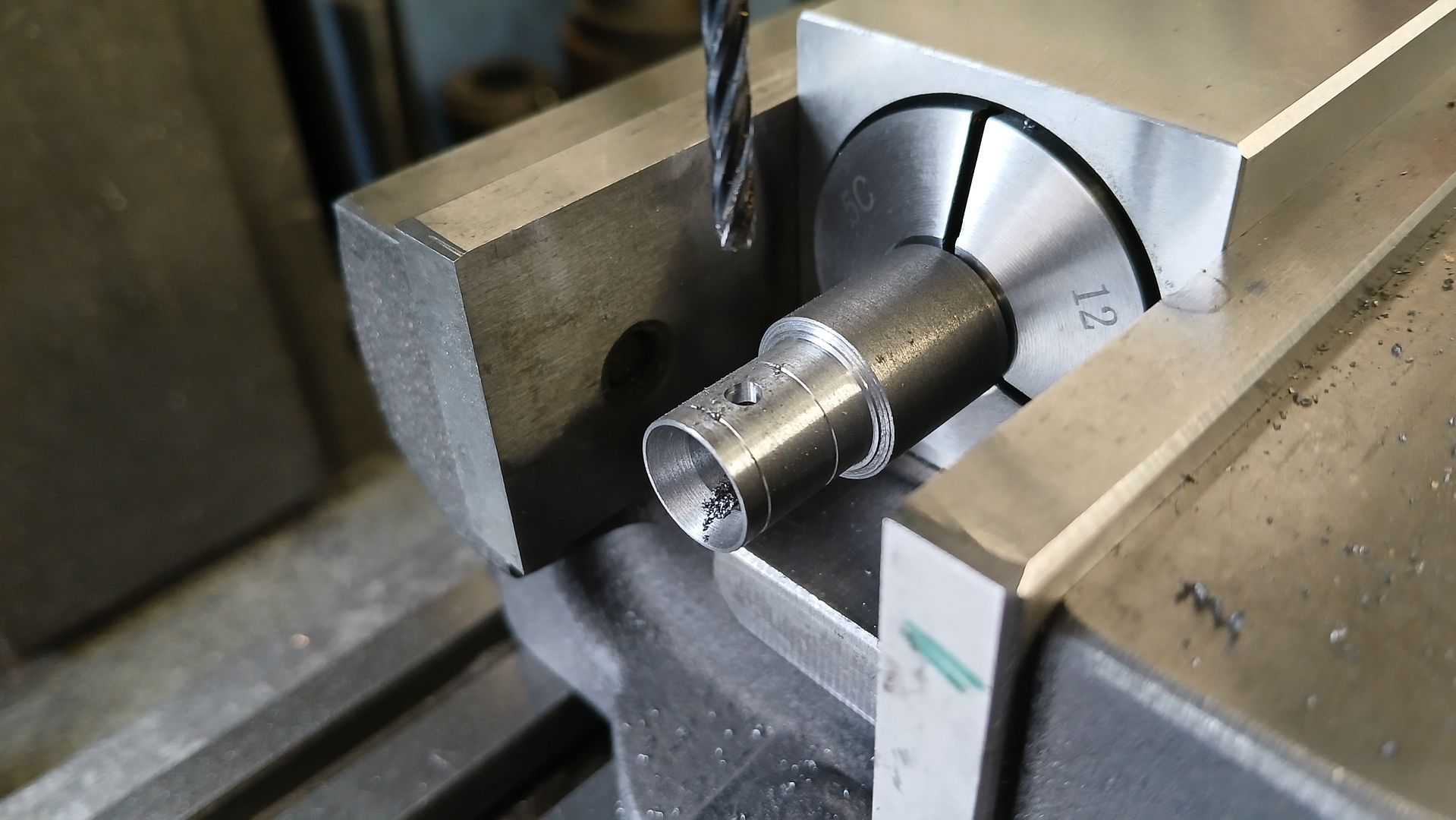
After adding a couple of oil grooves I held it in a collet block to drill and ream for the 3mm wrist pin. Then I sawed it off from the stock and faced the top. Lastly it was lapped into the cylinder with 1000g silicon carbide
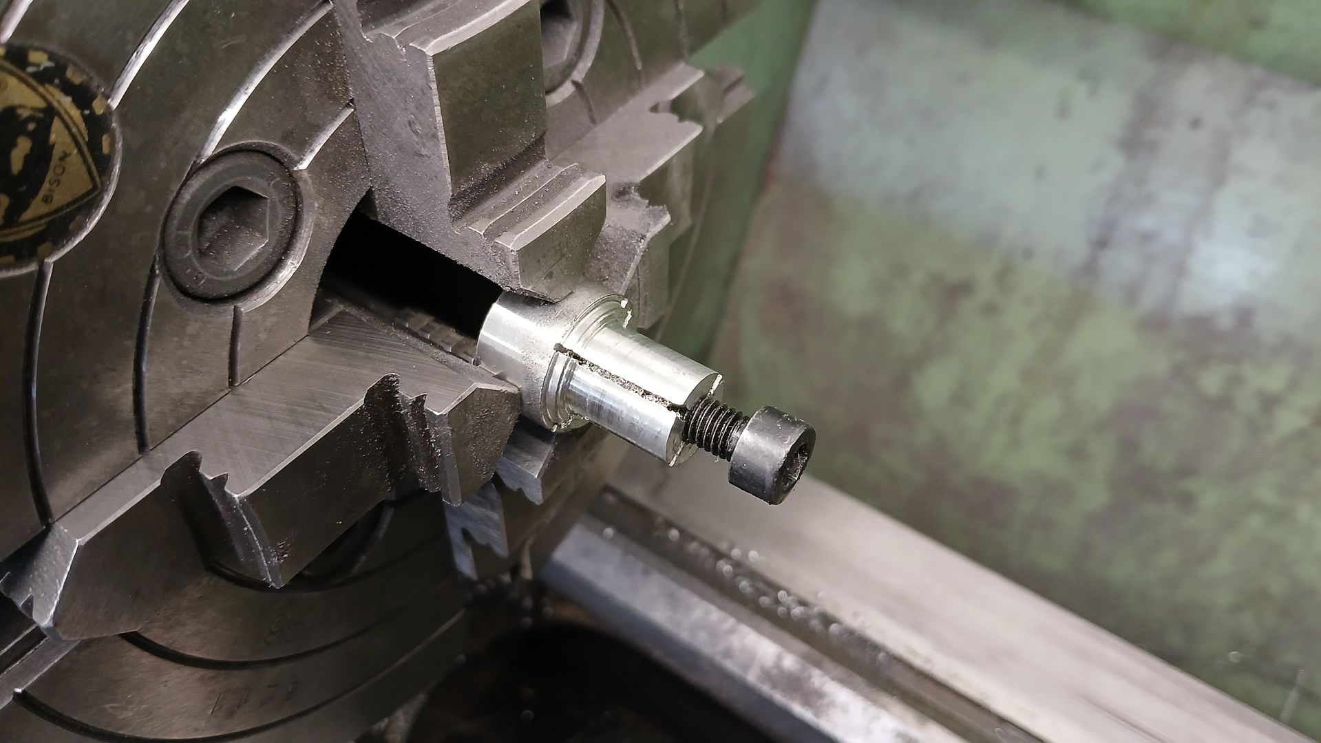
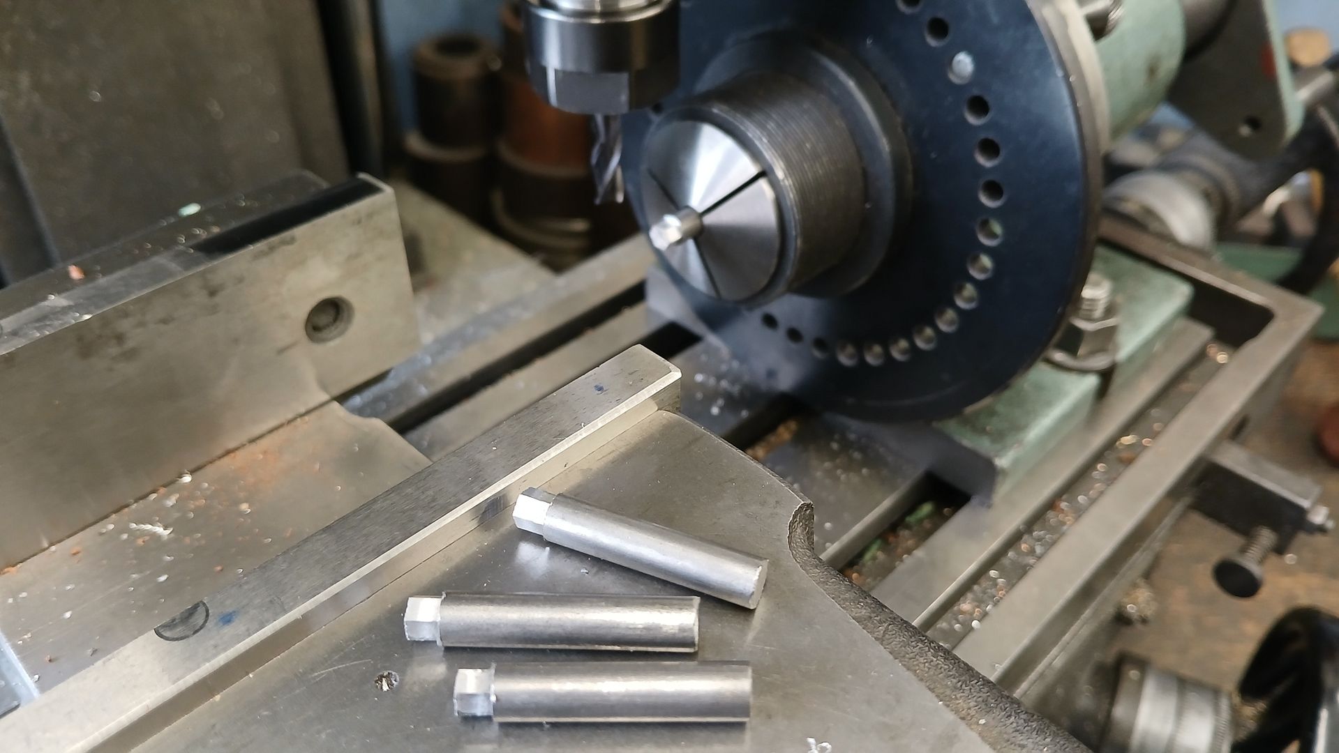
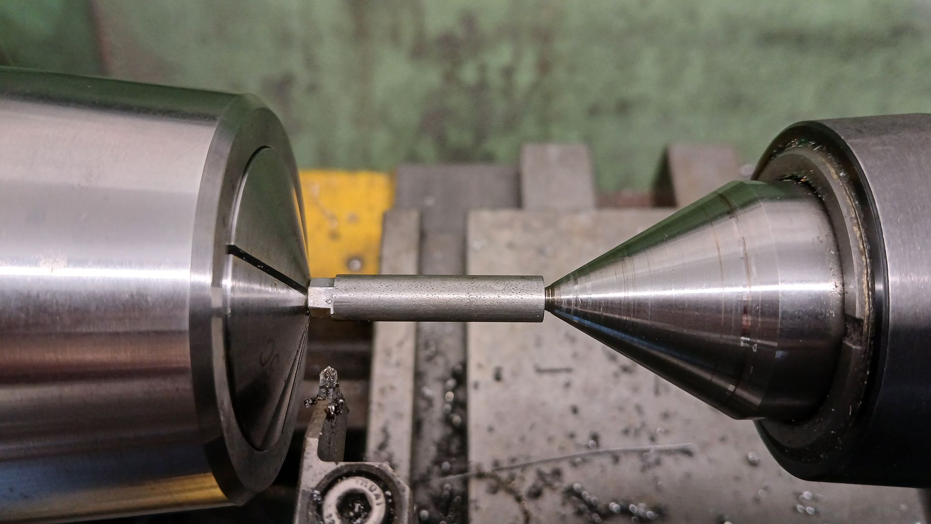
The cylinder stands on 4 legs, I started by cutting a hex on the ends. Then faced them down to length, centre drilled and tapped both ends M2.5
I then held a short length of 2.5mm dia material that had a thread on the end and used that to hold and drive the columns while supporting the other end with the tailstock. The top was reduced from the 6mm stock down to 4.5mm and the middle of the column to 3.5mm.
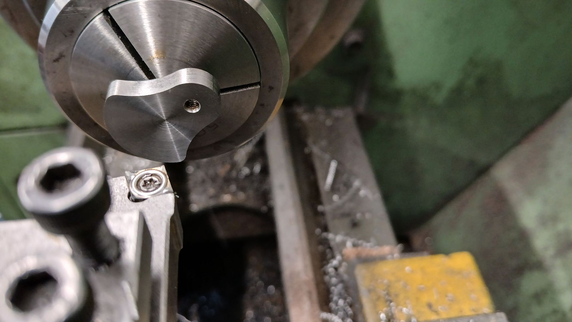
The crank was drilled and reamed on the end of some bar and then shaped to profile after being sawn off it was Loctited to the end of the 6mm crankshaft which had been reduced to 5mm. Once set the sawn side was faced back to final thickness.
The flywheel was turned from some 40mm dia cast iron bar and reamed 5mm. After drilling and tapping for a grub screw I used the CNC to cut the recess on each side which is easier than face grooving on the lathe.
The piston valve was turned from 6mm stainless steel, just facing and cutting a waist in the middle with a small parting tool
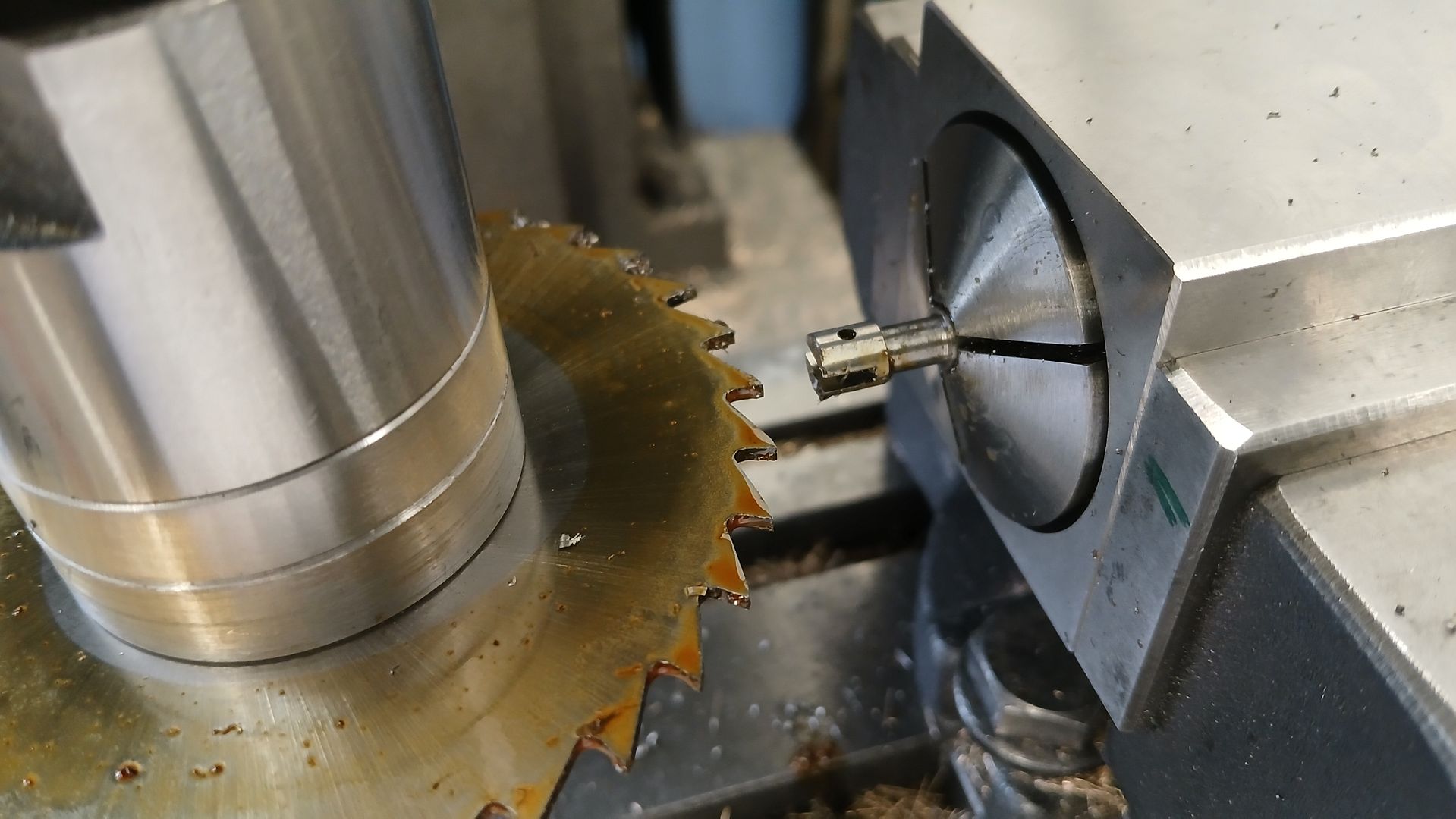
A 1.5mm slitting saw was used to cut the slot for the eccentric rod, a 1.6mm hole was drilled in one side and a M1.6 thread cut in the other for a 4.5mm long x 1.6mm pin.
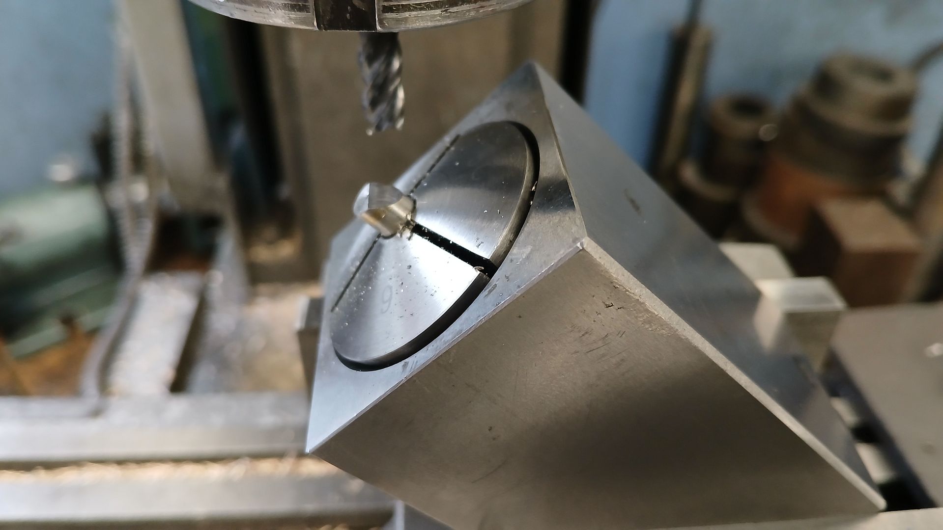
Then the top was milled to 45deg for half it’s width
A piece of brass was bored for the eccentric and drilled for the pivot pin.
Then machined to shape
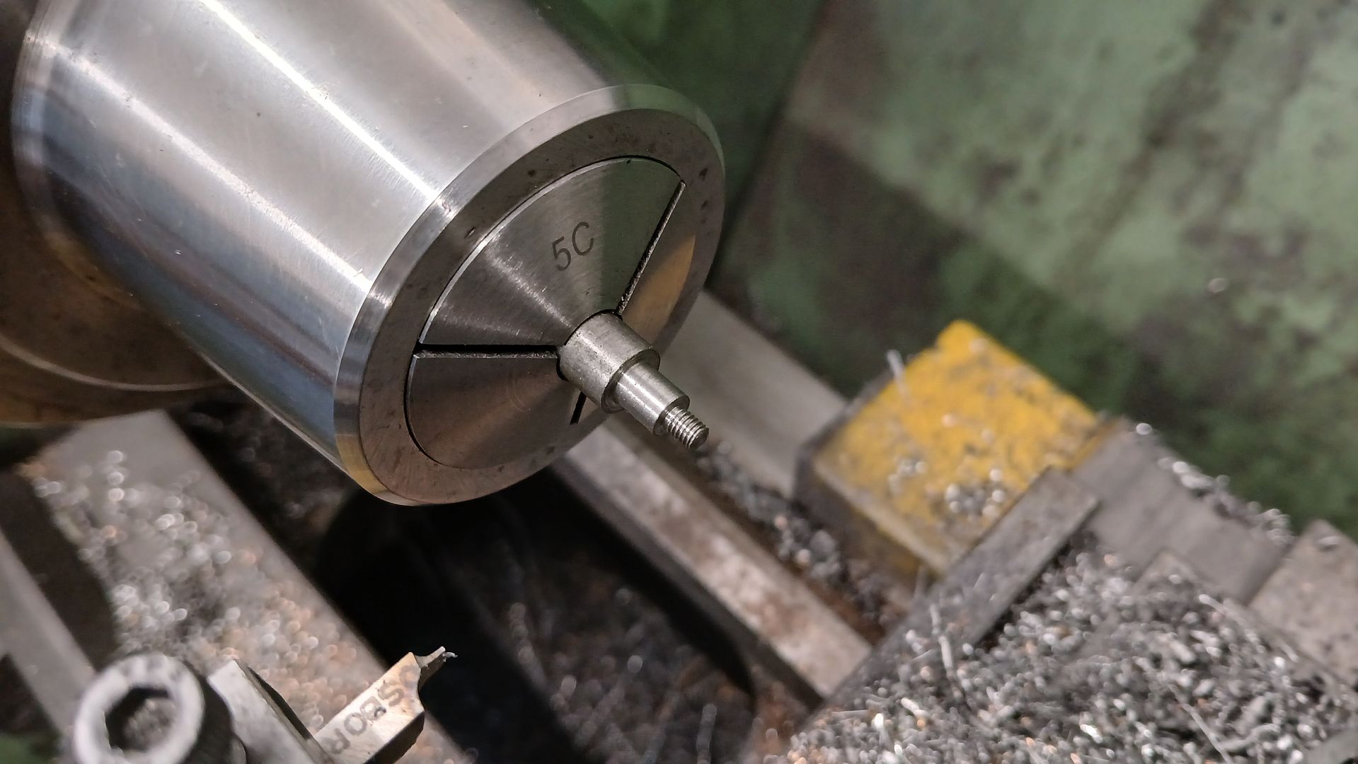
The eccentric was faced and turned to fit the strap and then the 5C chuck moved to the lathe so the hole could be drilled and reamed true to the outer surface. After tapping for a grub screw it was sawn off and then mounted on a stub of 6mm rod to face the sawn side back to final width.
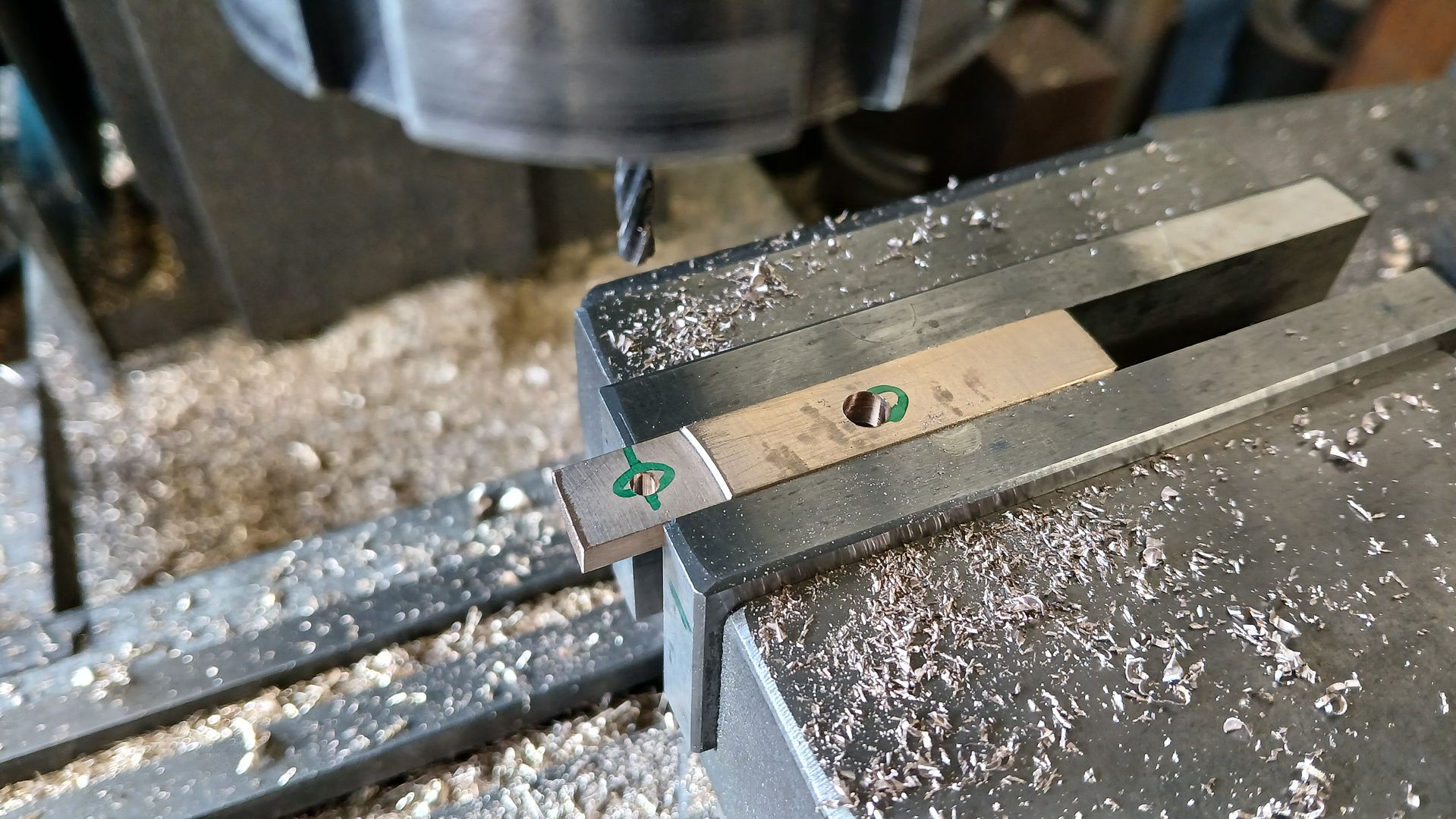
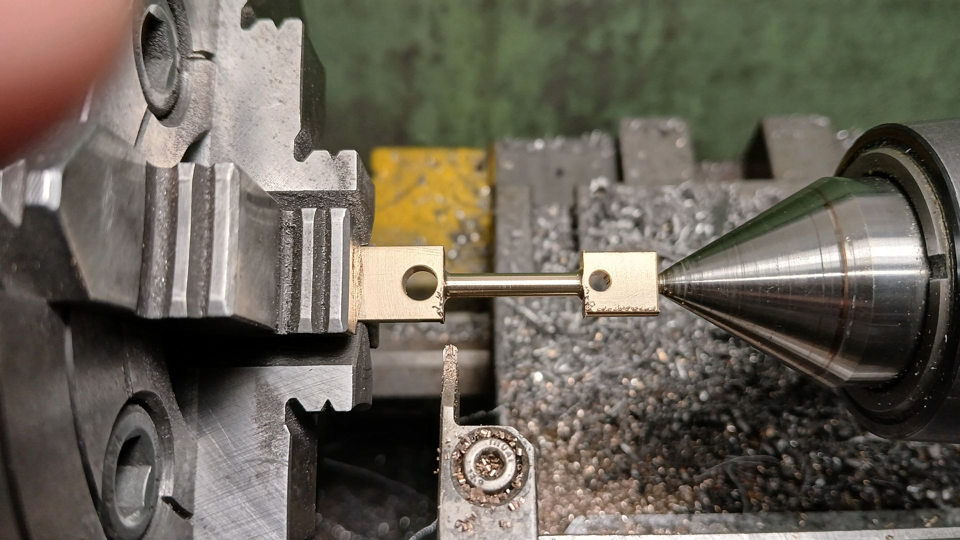
The conrod brank was machined up and reamed for the two holes
Then the middle section turned. I picked the ctrs for the 1mm internal radii from the wrong plane on the drawing so they come a bit close to the holes but a bit of adjustment of the outer diameters at each end soon sorted that out.
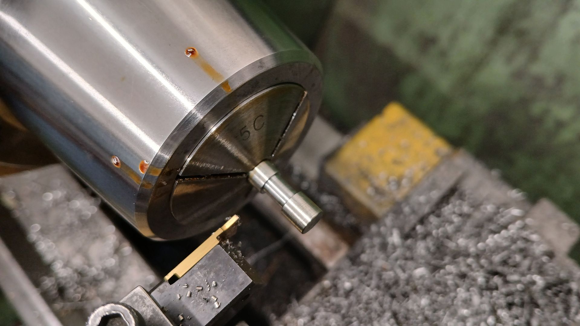
The crank pin was simple turning and threading. The narrow HSS blade gave an undercut to the thread ensuring the pin pulled up true to the face of the crank web.
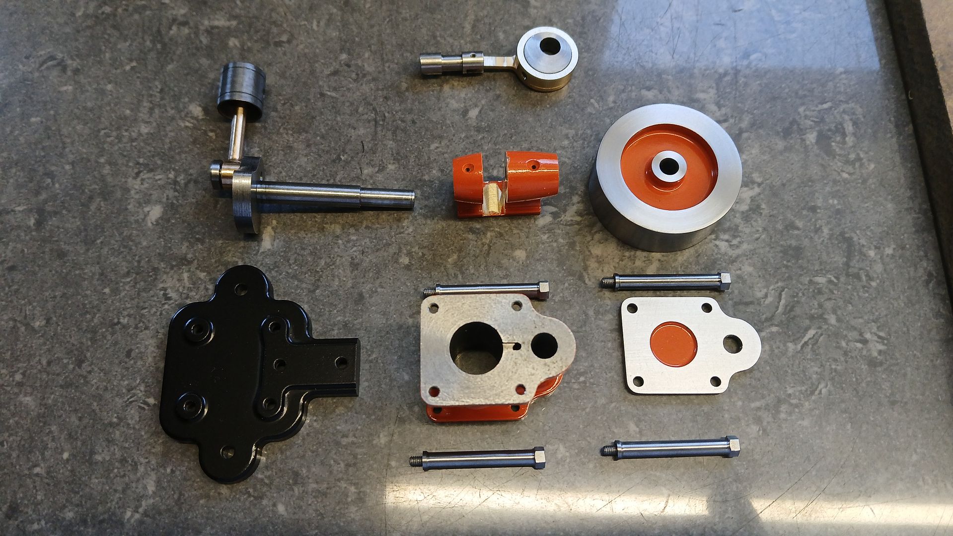
That’s all the bits made and ready for paint but that will have to wait until next time.
Painting did not take long as there are not many parts and those that do need painting are small.
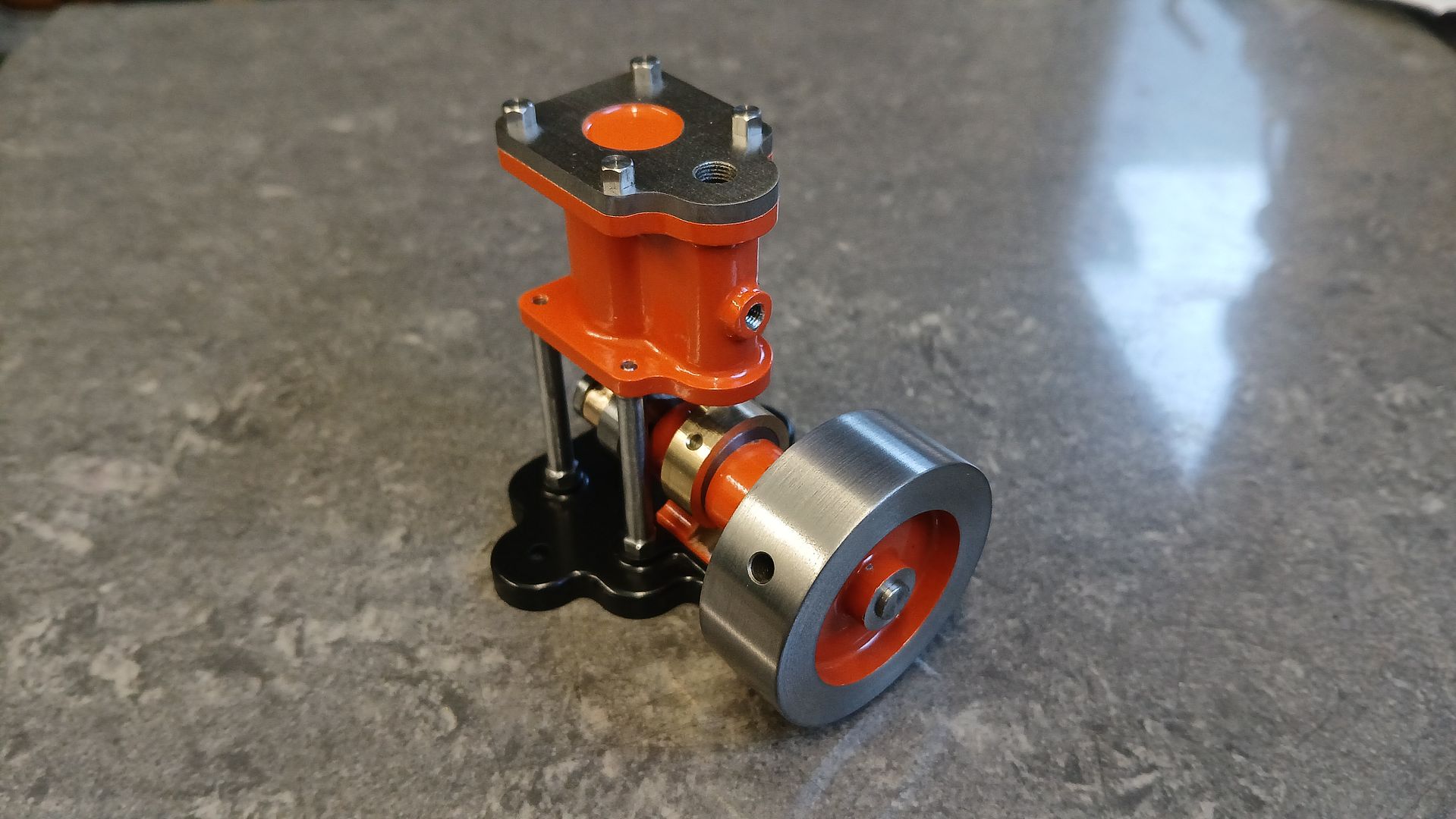
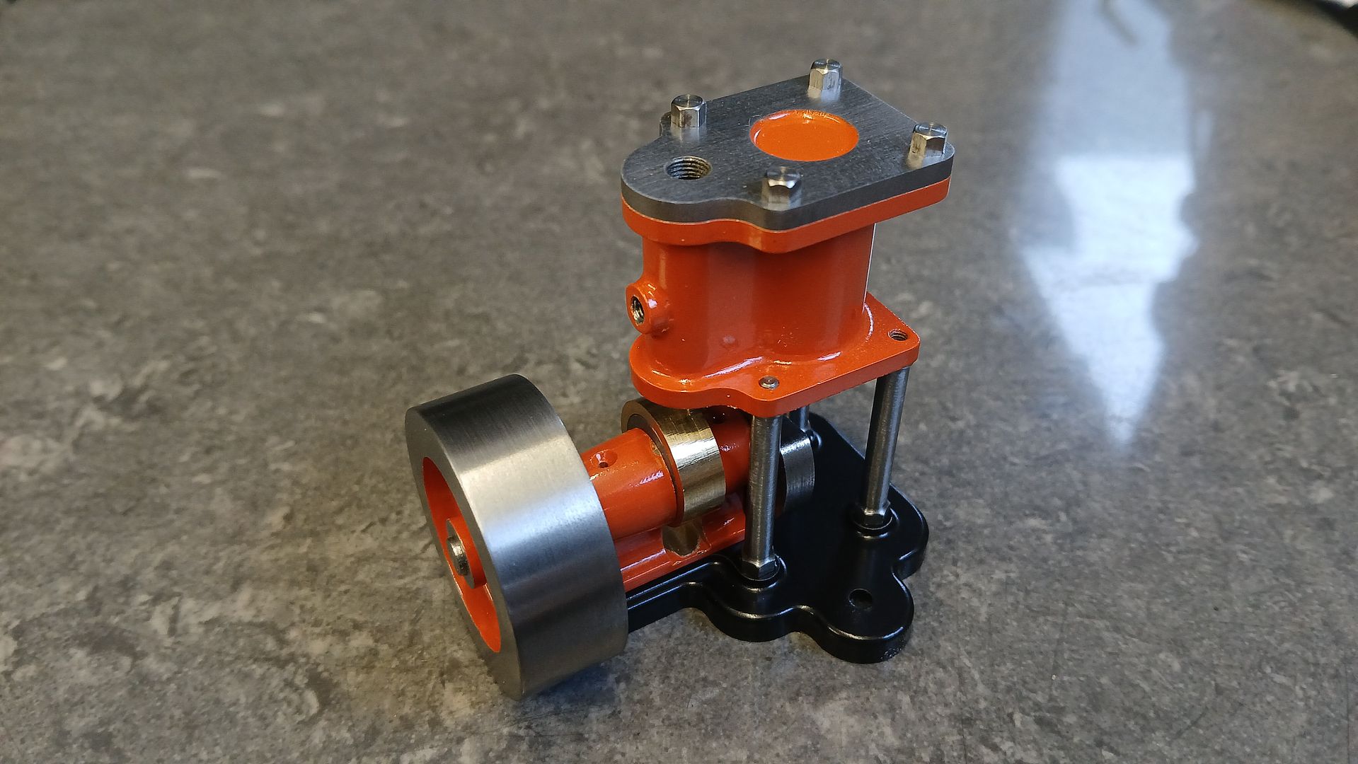
In the end I decided to paint the edges of the cylinder flanges rather than leave them bare iron as I had them on the 3D rendering. I left the smaller sub assemblies together after test running which ensured they went back together the same way.
It was then just a case of putting it back together and having a play. Like the little Husky which is also single acting and has the air/steam coming in and out the same hole it needs a bit more pressure than I usually run at but ticks over quite happily and also has a good turn of speed (tacho reading at the end of the video.
These little engines are quite good fun projects that can be slipped in during a longer build. They also suit smaller indoor machines for those that don’t want to venture out into a cold workshop for the next 5 months. material costs are low and if you muck something up then you have not got to source a replacement casting.